2AAGMGC02SALTE Cat1-bis module
Sequans Communications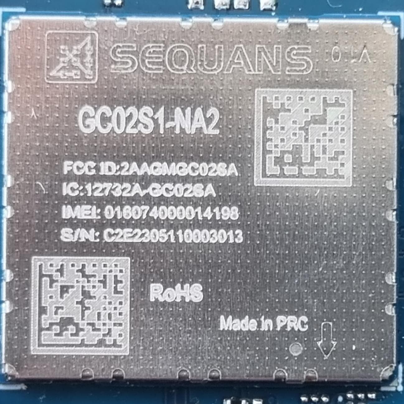
Click to zoom
Application Details
- Equipment Class
- CXX - Communications Rcvr for use w/ licensed Tx and CBs
- Date of Grant
- Dec 12, 2023
- Application Purpose
- Original Equipment
- Date of Application
- Dec 11, 2023
- Equipment Note
- LTE Cat1-bis module
- Frequency Range
- 758.00000000 - 768.00000000
- Company
- Sequans Communications
- Country
- United States
Documents & Files
Document Text
Text extracted from the exhibit documents filed with the FCC. Open a document above to read the original.
Users Manual
SEQUANS Communicati ons 15-55 , Boulev ardCharles d e Gaulle 92700 Colombes, France Phone.+33.1.70.72.16.00 Fax. +33.1.70.72.16.09 contact@ sequans.com Calliope2P latform GC02S1DataSh eet(Pr eliminar y) GC02S1 Module www. sequans .com iiAbout this Data Sheet ABOUT THIS DATA SHEET Purpose and Scope The GC02S1 modules ar e complete LTE Cat1 systems including base-band, RF and memory, tar geting mass- mark et wear ables, consumers and M2M / IoT devices. This document provides the technical information about the GC02S1 L GA module family. Calliope 2 modules are based on Sequans’s SQN3530 chipset. Changes in this Document This is the seventh preliminary (P6a) revision of the document, superseding version P6 (October 2023). Table 1 . Revision and changes Rev .Da teChanges P6aNov . 2023 •Add a warning about antenna efficiency •Change FCC and ISED maximum allowed gain in Regulatory Information •Factory Reset now correctly references AT+SQNFACTORY... commands •New style sheet P6Oct. 2023 •Add FCC certification statement •Detail conditions for RF sensitivity measurements •Shows wha t pin numbers USB signals ar e connected to in Figure 4 (on page 17) P5Oct. 2023 •Reinstate the frequency band table •Reinstate mechanical section •Modify primary function of pins 21 to 24 (GPIO instead of UAR T 3) •Specify that SIM0_DETECT is not polarity programmable •Update marking for -2 series •Add further hardware/routing recommendations •Note about USB_VBUS being tied to WAKE4 •Add RF sensitivities for -NA2 model P4June 2023 •Mer ge with contents of the Module Integration Guide and Module Manufac turing Guide documents. General overhaul. iii Table 1 . Revision and changes (continued) Rev .Da teChanges P3Nov . 2022 •Added band 14 (NA2 model) •Added section 3.1.2 and table 15 •Added description/info of signals TX_IND, Status LED and USBREADY •Added emergency shut down function for WAKE2 •Updated band grouping in section 1.1 •Updated section 2.3 USB •Updated info in table 19 P2Apr . 2022 •Added operating bands for the EU variant •Changes in recommended voltage operating range in § 3.3.2 •Added marking info for JP and EU variants P1Feb . 2022N/A CONTENTS About this Da ta Sheet....................................................................................................................................ii 1. General Description...............................................................................................................7 1.1. Frequency Bands.............................................................................................................................7 1.2. Block Diagram.................................................................................................................................7 1.3. General Featur es.............................................................................................................................8 1.4. Applications.....................................................................................................................................8 1.5. Available Par t Numbers..................................................................................................................9 2. Interfaces.............................................................................................................................10 2.1. Pin Assignment..............................................................................................................................10 2.2. UAR T...............................................................................................................................................10 2.2.1. Intr oduction.........................................................................................................................10 2.2.2. UAR T Electrical Char acteristics........................................................................................11 2.2.3. UAR T Signals......................................................................................................................12 2.2.4. UAR T 0 Interface................................................................................................................14 2.2.5. UAR T 1 Interface................................................................................................................14 2.2.6. UAR T 2 Interface................................................................................................................15 2.2.7. UAR T 3 Interface................................................................................................................15 2.3. USB..................................................................................................................................................15 2.4. USIM Interfaces.............................................................................................................................18 2.5. I²C....................................................................................................................................................19 2.6. PCM/I²S...........................................................................................................................................20 2.7. SPI....................................................................................................................................................20 2.8. GPIO...............................................................................................................................................20 2.9. Other Signals.................................................................................................................................22 2.10. JT AG.............................................................................................................................................26 2.11. Antenna........................................................................................................................................…
Text truncated - open the document above for the full version.
Attestation Statements
Date: 02/10/2023 Federal Communications Commission Equipment Authorization Branch 7435 Oakland Mills Rd. Columbia MD 21046 FCC ID: 2AAGMGC02SA To whom it may concern: We, Sequans Communications 90 Washington Valley Rd, Bedminster, New Jersey, 7921, USA Hereby certify that, •the equipment for which authorization is sought is not “covered” equipment prohibited from receiving an equipment authorization pursuant to section 2.903 of the FCC rules. •as of the date of the filing of the application, the applicant is not identified on the Covered List as an entity producing “covered” equipment. Sincerely, ________________________________________ By: Sunpreet Kaur Title: NAM & EMEA Certification Manager Telephone: +12062476609 email: [email protected]
Attestation Statements
Certification designating a U.S. agent for service of process. (as required by section 2.911(d) (7)) Date: 02/10/2023 Federal Communications Commission Equipment Authorization Branch 7435 Oakland Mills Rd. Columbia MD 21046 FCC ID: 2AAGMGC02SA To whom it may concern: We, Sequans Communications 90 Washington Valley Rd, Bedminster, New Jersey, 7921, USA FRN: 0034219402 hereby certify that the following company, Sequans Communications 90 Washington Valley Rd, Bedminster, New Jersey, 7921, USA FRN: 0034219402 is our designated U.S. agent for service of process and we acknowledge: •our consent to accept service of process in the United States for matters related to the applicable equipment at the physical U.S. address and email address of the designated U.S. agent •the acceptance to maintain an U.S. agent for no less than one year after the grantee has terminated all marketing and importation or the conclusion of any Commission-related proceeding involving the equipment. Sincerely, By: Sunpreet Kaur Title: NAM & EMEA Certifications Manager Telephone: +1.206.248.6609 email: [email protected] We Sequans Communications acknowledge our obligation to accept service of process in the United States for matters related to the applicable equipment at our physical U.S. address and email address stated above. Sincerely, By: Sunpreet Kaur Title: NAM & EMEA Certifications Manager Telephone: +1.206.248.6609 email: [email protected]
Cover Letter(s)
Date: 02/10/2023 Federal Communications Commission Equipment Authorization Branch 7435 Oakland Mills Rd. Columbia MD 21046 FCC ID: 2AAGMGC02SA To whom it may concern: We, Sequans Communications 90 Washington Valley Rd, Bedminster, New Jersey, 7921, USA hereby authorize, DEKRA Testing and Certification S.A.U. Parque Tecnológico de Andalucía C/Severo Ochoa, 2 & 6 | 29590 | Málaga | Spain Agent: Álvaro Corrales Sedeño e-mail:[email protected] Phone:+34 952 619 198 to act as our agent in the preparation of this application for equipment certification, including the signing of all documents relating to these matters. We also hereby certify that neither we nor any party to this application are subject to a denial of U.S. Federal benefits, which include FCC benefits, pursuant to Section 5301 of the Anti-Drug Abuse Act of 1988, U.S.C. 862 because of conviction for possession or distribution of controlled substance. For instances where our authorized agent signs the application for certification on our behalf, I acknowledge that all responsibility for complying with the terms and conditions for Certification, as specified by DEKRA Testing and Certification, S.A.U., still resides with us. This agreement expires one year from the current date. Sincerely, ________________________________________ By: Sunpreet Kaur Title: NAM & EMEA Certification Manager Telephone: +12062476609 email: [email protected]
Cover Letter(s)
Date: 02/10/2023 Federal Communications Commission Equipment Authorization Branch 7435 Oakland Mill s Rd. Columbia MD 21046 FCC ID: 2AAGMGC02SA To whom it may concern: We, Sequans Communications 90 Washington Valley Rd, Bedminster, New Jersey, 7921, USA hereby request requests that a part of the subject FCC application be held confidential to avoid release of sensitive information of the product to the public pursuant to §0.457(d)(1)(ii) and §0.459 of the Commission’s Rules (47 C.F.R.) and §552 (b)(4) of the Freedom of Information Act, For the product stated above, we request that the following information be withheld from public disclose: Type of Confidentiality Requested Exhibit Short Term Permanent Block Diagrams Short Term Permanent Operation Description Short Term Permanent Schematics Short Term Permanent Parts List & Placement/BOM Short Term Permanent Tune-Up Procedure Short Term Permanent SDR Software and Security Information Short Term Test Setup Photos Short Term User’s Manual Short Term External Photos Short Term Internal Photos Permanent Confidentiality: The above materials contain trade secrets and proprietary information not customarily released to the public. The public disclosure of these matters might be harmful to us and provide unjustified benefits to our competitors. Short-Term Confidentiality: We hereby request short-term confidentiality for the product stated above to avoid premature release of sensitive information prior to marketing or release of the product to the public. Release date of short-term confidentiality is: 45 days from grant date marked 90 days from grant date marked 135 days from grant date marked 180 days from grant date marked Specific date: We are also aware that we are responsible to notify DEKRA Testing and Certification S.A.U. in the event information regarding the product or the product is made available to the public. DEKRA Testing and Certification S.A.U. will then release the documents listed above for public disclosure pursuant to FCC Public Notice DA 04-1705. Sincerely, ________________________________________ By: Sunpreet Kaur Title: NAM & EMEA Certification Manager Telephone: +12062476609 email: [email protected]
Cover Letter(s)
Date: 02/10/2023 Federal Communications Commission Equipment Authorization Branch 7435 Oakland Mill s Rd. Columbia MD 21046 FCC ID: 2AAGMGC02SA To whom it may concern: We, Sequans Communications 90 Washington Valley Rd, Bedminster, New Jersey, 7921, USA through the following attestation, hereby address the requirements to support modular approval pursuant to §15.212 of the Commission’s Rules: Modular approval requirement Yes No* (i)The radio elements of the modular transmitter must have their own shielding. The physical crystal and tuning capacitors may be located external to the shielded radio elements. X (ii)The modular transmitter must have buffered modulation/data inputs (if such inputs are provided) to ensure that the module will comply with part 15 requirements under conditions of excessive data rates or over-modulation. X (iii)The modular transmitter must have its own power supply regulation.X (iv)The modular transmitter must comply with the antenna and transmission system requirements of §§15.203, 15.204(b) and 15.204(c). The antenna must either be permanently attached or employ a “unique” antenna coupler (at all connections between the module and the antenna, including the cable). The “professional installation” provision of §15.203 is not applicable to modules but can apply to limited modular approvals under paragraph (b) of this section. X (v)The modular transmitter must be tested in a stand-alone configuration, i.e., the module must not be inside another device during testing for compliance with part 15 requirements. Unless the transmitter module will be battery powered, it must comply with the AC line conducted requirements found in §15.207. AC or DC power lines and data input/output lines connected to the module must not contain ferrites, unless they will be marketed with the module (see §15.27(a)). The length of these lines shall be the length typical of actual use or, if that length is unknown, at least 10 centimeters to ensure that there is no coupling between the case of the module and supporting equipment. Any accessories, peripherals, or support equipment X connected to the module during testing shall be unmodified and commercially available (see §15.31(i)). (vi) The modular transmitter must be equipped with either a permanently affixed label or must be capable of electronically displaying its FCC identification number. X (vii) The modular transmitter must comply with any specific rules or operating requirements that ordinarily apply to a complete transmitter and the manufacturer must provide adequate instructions along with the module to explain any such requirements. A copy of these instructions must be included in the application for equipment authorization. X (viii) The modular transmitter must comply with any applicable RF exposure requirements in its final configuration. X * Shall provide a detailed explanation if the answer is “No”. Sincerely, ________________________________________ By: Sunpreet Kaur Title: NAM & EMEA Certification Manager Telephone: +12062476609 email: [email protected]
Cover Letter(s)
Date: 02/10/2023 Federal Communications Commission Equipment Authorization Branch 7435 Oakland Mills Rd. Columbia MD 21046 FCC ID: 2AAGMGC02SA To whom it may concern: We, Sequans Communications 90 Washington Valley Rd, Bedminster, New Jersey, 7921, USA through the following attestation, hereby address the fourth requirement to support modular approval. •This device is designed for mobile or fixed operation; portable operation is subject to a Class 2 permissive change application or to a new and separate FCC ID. •The maximum antenna gain is limited to those calculated in the RF exposure exhibit. •The product has an FCC ID label on the device itself. Also, the OEM host product manufacturer will be informed to display a label referring to the enclosed module. •We request to include in the grant the following words in the device description or grant notes: “modular transmitter” or “transmitter module”. If there are any additional questions or if further information is needed, please contact us. Sincerely, ________________________________________ By: Sunpreet Kaur Title: NAM & EMEA Certification Manager Telephone: +12062476609 email: [email protected]
ID Label/Location Info
1. The triangle in the bottom-right corner provides pin #1 location. 2. FCC ID: 2AAGMGC02SA 3. IC: 12732A-GC02SA 4. IMEI:XXXXXXXXXXXXXXX 5. S/N:C2AYYMMDDNNNNSSS (16 digits) • C2A: reserved, value subject to change at Sequans’s discretion (3 digits); • YYMMDD: Manufacturing Date (YY:Year;MM:Month,DD:Day); • NNNN: Panel counter (from 0001~9999); • SSS: Piece location on panel (from 001~036) 6. 2D marked “a” refer to IMEI Barcode 7. 2D marked “b” refer to S/N Barcode
RF Exposure Info
DEKRA Testing and Certification, S.A.U. Parque Tecnológico de Andalucía, c/ Severo Ochoa nº 2 · 29590 Campanillas · Málaga · España C.I.F. A29 507 456 Report No: (NIE) 75461RAN.001 2023-11-15 Test report No: NIE: 75461RAN.001 Assessment report RF EXPOSURE REPORT ACCORDING TO FCC 47 CFR Part 2.1091 (*) Identification of item under evaluation LTE Cat1-bis module (*) Trademark Sequans Communications (*) Model and /or type reference GC02S1-NA2 (*) Other identification of the product HW version: Rev1 SW Version: LR9.0.1.1-59215 IMEI TAC: 01607400 FCC ID: 2AAGMGC02SA IC: 12732A-GC02SA (*) Features 4G LTE module 3GPP 4G Release 14, LTE Category CAT1_BIS One antenna port Bands supported : 2, 4, 5, 12, 13, 14, 17, 25, B66 [MFBI] is supported : 25[2]/66[4]/12[17]/13/14/5 LGA Module Dual (U)SIM Card Interface SMS over IMS or NAS 10Mbps / 5Mbps DL/UL throughput (*) Manufacturer Sequans Communications 55 Boulevard Charles de Gaulle, 92700 Colombes Test method requested, standard FCC 47 CFR Part 2.1091 Radiofrequency radiation exposure evaluation: mobile devices. Summary IN COMPLIANCE Approved by (name / position & signature) Miguel Lacave Antennas Lab Manager Date of issue 2023-11-15 Report template No FAN36_01 (*) “Data provided by the client” DEKRA Testing and Certification, S.A.U. Parque Tecnológico de Andalucía, c/ Severo Ochoa nº 2 · 29590 Campanillas · Málaga · España C.I.F. A29 507 456 Report No: (NIE) 75461RAN.001 Page 2 of 11 2023-11-15 Index Competences and guarantees .................................................................................................... 3 General conditions ...................................................................................................................... 3 Data provided by the client .......................................................................................................... 3 Identification of the client............................................................................................................. 3 Document history ........................................................................................................................ 4 Appendix A: FCC RF Exposure assessment result ..................................................................... 5 General description of the equipment under evaluation ............................................................ 6 Maximum Antenna Gain determination for RF Exposure compliance ....................................... 7 Appendix B: FCC RF Exposure information ................................................................................ 9 FCC RF Exposure evaluation ................................................................................................. 10 FCC MPE Evaluation .............................................................................................................. 11 FCC Cellular bands limits ....................................................................................................... 11 DEKRA Testing and Certification, S.A.U. Parque Tecnológico de Andalucía, c/ Severo Ochoa nº 2 · 29590 Campanillas · Málaga · España C.I.F. A29 507 456 Report No: (NIE) 75461RAN.001 Page 3 of 11 2023-11-15 Competences and guarantees In order to assure the traceability to other national and international laboratories, DEKRA Testing and Certification, S.A.U. has a calibration and maintenance program for its measurement equipment. DEKRA Testing and Certification, S.A.U. guarantees the reliability of the data presented in this report, which is the result of the measurements and the tests performed to the item under test on the date and under the conditions stated on the report and, it is based on the knowledge and technical facilities available at DEKRA Testing and Certification, S.A.U. at the time of performance of the test. DEKRA Testing and Certification, S.A.U. is liable to the client for the maintenance of the confidentiality of all information related to the item under test and the results of the test. The results presented in this Assessment Report apply only to the particular item under test established in this document. IMPORTANT: No parts of this report may be reproduced or quoted out of context, in any form or by any means, except in full, without the previous written permission of DEKRA Testing and Certification, S.A.U. General conditions 1. This report is only referred to the item that has undergone the assessment. 2. This report does not constitute or imply on its own an approval of the product by the Certification Bodies or competent Authorities. 3. This document is only valid if complete; no partial reproduction can be made without previous written permission of DEKRA Testing and Certification, S.A.U. 4. This test report cannot be used partially or in full for publicity and/or promotional purposes without previous written permission of DEKRA Testing and Certification, S.A.U. and the Accreditation Bodies Data provided by the client The following data has been provided by the client: 1. Information relating to the description of the sample ("Identification of the item under evaluation", "Trademark", "Model and/or type reference", “General description of the device”, “Other identification of the product”). 2. Request for evaluation under mobile exposure conditions. 3. The device under evaluation consists of a module based on Sequans’s second-generation Calliope 2 silicon and delivers optimized 4G LTE Cat 1 connectivity for IoT, M2M and consumer devices such as wearables and hearables that require voice support and speed higher than LTE-M. DEKRA Testing and Certification, S.A.U. declines any responsibility with respect to the information provided by the client and that may affect the validity of results. Identification of the client Company name: Sequans Communications Postal address: 55 Boulevard Charles de Gaulle, 92700 Colombes Contact person: Julien Arondel Telephone / e-mail: +33607552782 / [email protected] DEKRA Testing and…
Text truncated - open the document above for the full version.
Test Report
DEKRA Testing and Certification, S.A.U. Parque Tecnológico de Andalucía, c/ Severo Ochoa nº 2 · 29590 Campanillas · Málaga · España C.I.F. A29 507 456 Report No: 75461REM.001 2023-11-08 Test report No: 75461REM.001 Test report FCC Rules and Regulations CFR 47, Part 15, Subpart B (10-1-21 Edition) & ICES-003 Issue 7 (October 2020) (*) Identification of item tested LTE Cat1-bis module (*) Trademark Sequans Communications (*) Model and /or type reference GC02S1-NA2 Other identification of the product Not provided data (*) Features Features: 4G LTE module 3GPP 4G Release 14, LTE Category CAT1_BIS One antenna port Bands supported : 2, 4, 5, 12, 13, 14, 17, 25, B66 [MFBI] is supported : 25[2]/66[4]/12[17]/13/14/5 LGA Module Dual (U)SIM Card Interface SMS over IMS or NAS 10Mbps / 5Mbps DL/UL throughput HW version: Rev1 SW version: LR9.0.1.1-59215 FCC ID: 2AAGMGC02SA IC: 12732A-GC02SA Manufacturer Sequans Communications 55 Boulevard Charles de Gaulle, 92700 Colombes Test method requested, standard FCC Rules and Regulations CFR 47, Part 15, Subpart B (10-1-21 Edition) & ICES-003 Issue 7 (October 2020) Summary IN COMPLIANCE Approved by (name / position & signature) José Manuel Gómez EMC Consumer & RF Lab. Manager Date of issue 2023-11-08 Report template No FDT08_24 (*) “Data provided by the client” DEKRA Testing and Certification, S.A.U. Parque Tecnológico de Andalucía, c/ Severo Ochoa nº 2 · 29590 Campanillas · Málaga · España C.I.F. A29 507 456 Report No: 75461REM.001 Page 2 of 39 2023-11-08 Index ACRONYMS ................................................................................................................................................................. 3 COMPETENCES AND GUARANTEES ....................................................................................................................... 3 GENERAL CONDITIONS ............................................................................................................................................. 3 UNCERTAINTY ............................................................................................................................................................ 3 DATA PROVIDED BY THE CLIENT ............................................................................................................................ 4 USAGE OF SAMPLES ................................................................................................................................................. 5 TEST SAMPLE DESCRIPTION ................................................................................................................................... 6 IDENTIFICATION OF THE CLIENT ............................................................................................................................. 7 TESTING PERIOD AND PLACE .................................................................................................................................. 7 DOCUMENT HISTORY ................................................................................................................................................ 7 ENVIRONMENTAL CONDITIONS ............................................................................................................................... 8 REMARKS AND COMMENTS ..................................................................................................................................... 9 TESTING VERDICTS ................................................................................................................................................... 9 LIST OF EQUIPMENT USED DURING THE TEST ..................................................................................................... 9 SUMMARY .................................................................................................................................................................. 10 APPENDIX A: TEST RESULTS ................................................................................................................................. 11 DESCRIPTION OF THE OPERATION MODES ........................................................................................................ 13 TEST STANDARDS VERSION APPLIED .................................................................................................................. 14 TEST CASES DETAILS ............................................................................................................................................. 15 DEKRA Testing and Certification, S.A.U. Parque Tecnológico de Andalucía, c/ Severo Ochoa nº 2 · 29590 Campanillas · Málaga · España C.I.F. A29 507 456 Report No: 75461REM.001 Page 3 of 39 2023-11-08 Acronyms Acronym ID Acronym Description Code EMC Test Code Freq Rng Frequency Range MP Measurement Point OM Operation Mode S/ Sample V Verdict Competences and guarantees DEKRA Testing and Certification S.A.U. is a testing laboratory accredited by the National Accreditation Body (ENAC -Entidad Nacional de Acreditación), to perform the tests indicated in the Certificate No. 51/LE 147. In order to assure the traceability to other national and international laboratories, DEKRA Testing and Certification S.A.U. has a calibration and maintenance program for its measurement equipment. DEKRA Testing and Certification S.A.U. guarantees the reliability of the data presented in this report, which is the result of the measurements and the tests performed to the item under test on the date and under the conditions stated on the report and, it is based on the knowledge and technical facilities available at DEKRA Testing and Certification S.A.U. at the time of performance of the test. DEKRA Testing and Certification S.A.U. is liable to the client for the maintenance of the confidentiality of all information related to the item under test and the results of the test. The results presented in this Test Report apply only to the particular item under test establi…
Text truncated - open the document above for the full version.
Test Report
Radial Isotropic Broadband Antenna OmniLOG ® 90200 Highly isotropic from 700MHz to 2,5GHz Optimal for usage with spectrum analyzer for radial isotropic measurements 90° knuckle base with SMA connector Small weight and very small dimensions 10 years warranty Highlights: For measurements in the 700MHz - 2,5GHz frequency range, specially GSM, UMTS and 2,4GHz WLAN Data sheet Rev 1.7 26.04.2012 w w w w 1 Made in Germany w Specifications Design: Omni-Directional Nominal impedance: 50 Ohms Frequency range: 700MHz - 2,5GHz VSWR (typ): < 3:1 RF-connection: SMA (male) Temperature range: - 20°C to +70°C Shock: 40G at 10msek Thermal Shock: - 20°C to +70°C:10 cycles Dimensions (L/W): 210 x 20mm Weight: 70gr Warranty: 10 years OmniLOG ® 90200 w w w w w w w 2 OmniLOG 90200 Antenna with Spectran HF-60100 V4. The antenna is directly supported by the V4 series. It can be used for the GSM and UMTS frequency range with the Rev.3 units too (measurement uncer- tainty only 2dB). OmniLOG with Spectran HF-XFR (OmniLOG 90200 Antenna already included with the Spectran HF-XFR) w w Front view OmniLOG 90200 Broadbandantenna Rear view Horizontal Pattern OmniLOG 90200 w 3 Frequency overview Analyzer & Antennas Frequency Overview SPECTRAN Spectrum Analyzer Frequency Overview HyperLOG and BicoLOG Antennas and Probes 4 References User of Aaronia Antennas and Spectrum Analyzers (Examples) Government, Military, aeronautic, astronautic NATO, Belgien Boeing, USA Airbus, Hamburg Bund (Bundeswehr), Leer Bun…
Text truncated - open the document above for the full version.
Contact Information
Applicant
Sunpreet Kaur(Certification Manager)
Test Firm
DEKRA Testing and Certification, S.A.U.Rafael Lopez Martin
Technical Specifications
| # | Rule Parts | Frequency Range | Power Output |
|---|---|---|---|
| 4 | 15B | 758 MHz - 768 MHz | - |
Other Applications from Sequans Communications
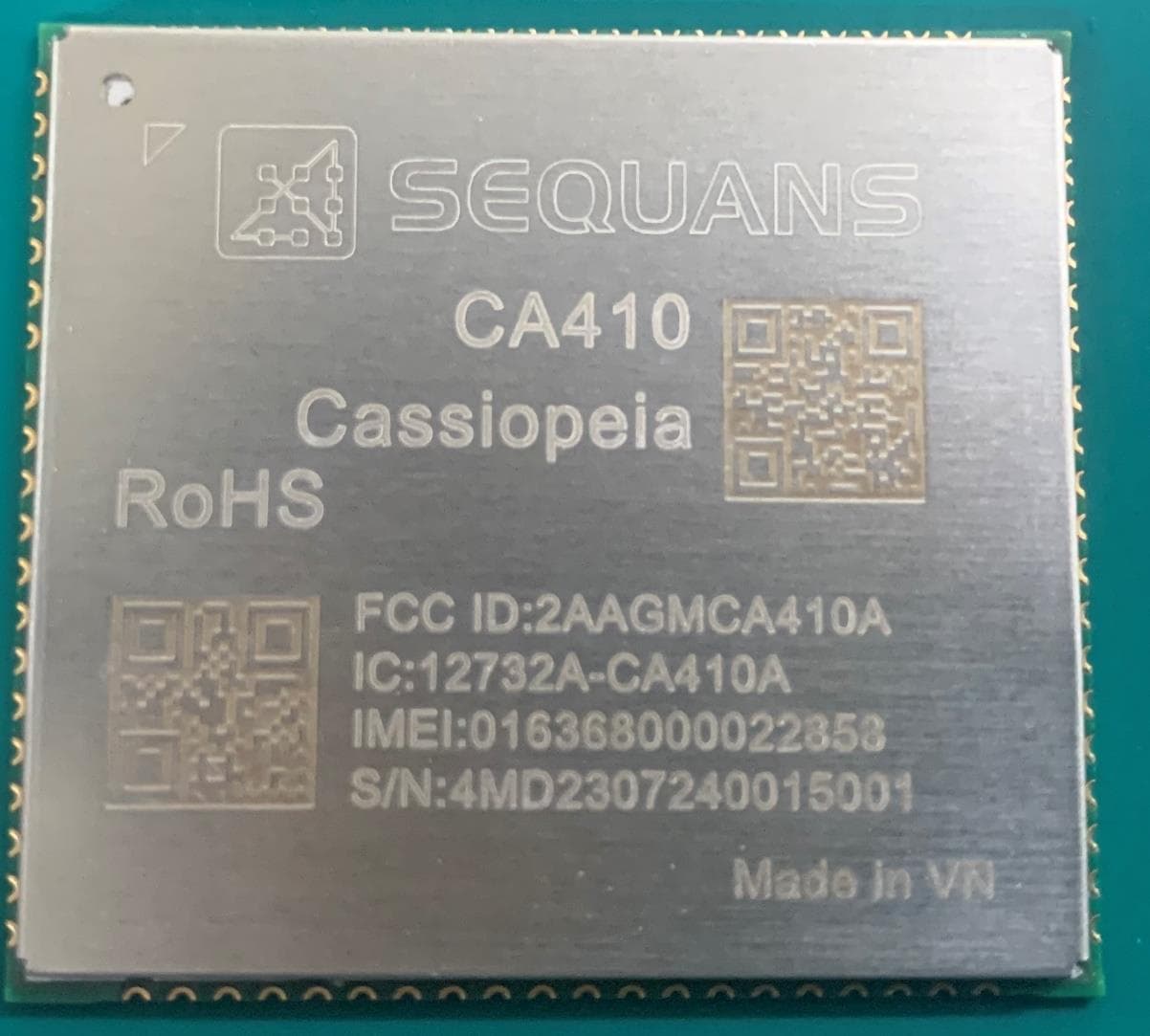
2AAGMCA410A
Nov 19, 2023LTE module
Equipment Class
PCB - PCS Licensed Transmitter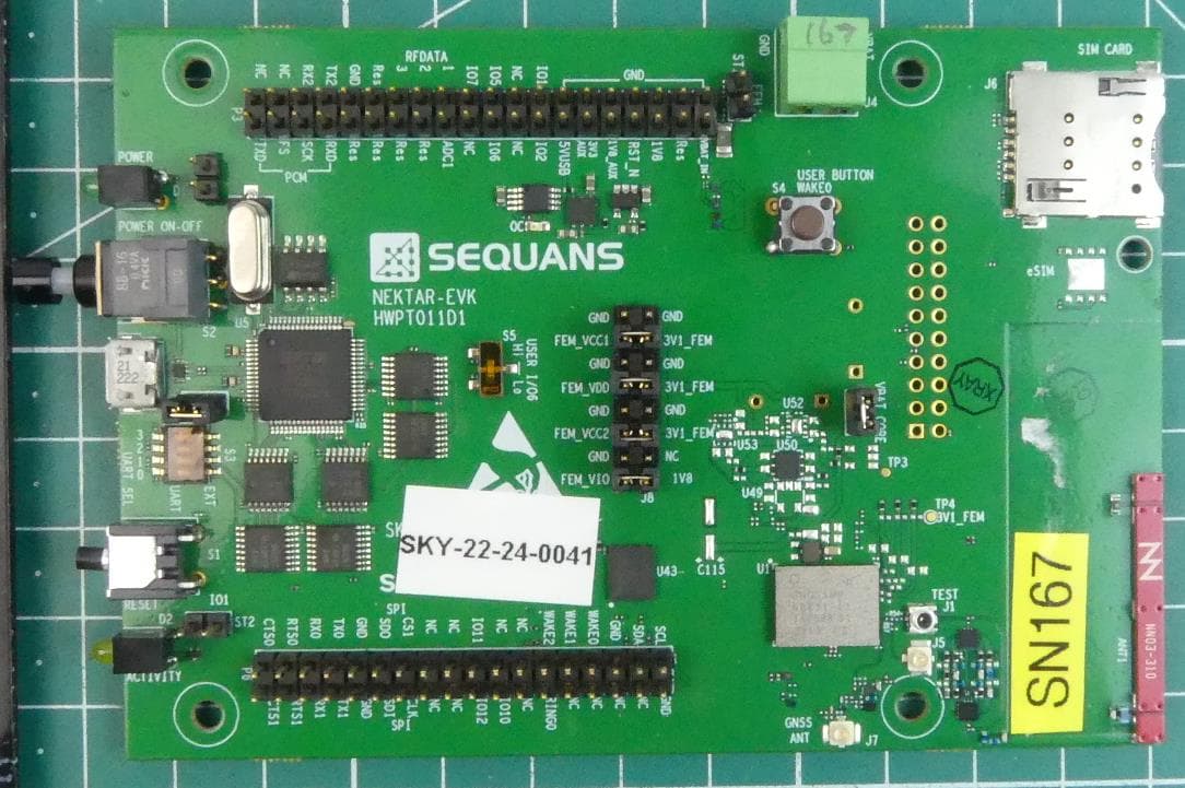
2AAGM66431
Dec 06, 2022SKY66431
Equipment Class
JAB - Part 15 Class B Digital Device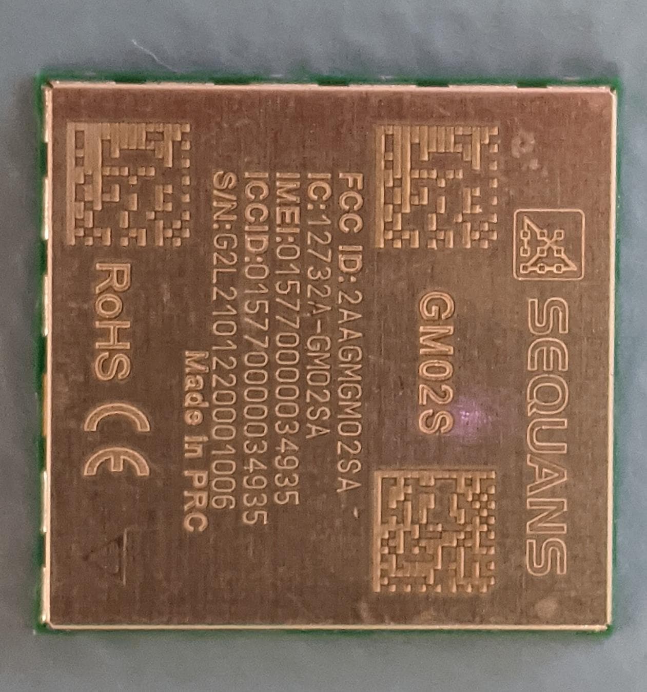
2AAGMGM02SA
Apr 15, 2021GM02S module
Equipment Class
JAB - Part 15 Class B Digital Device
2AAGMGM02S
Jan 17, 2021GM02S module
Equipment Class
PCB - PCS Licensed Transmitter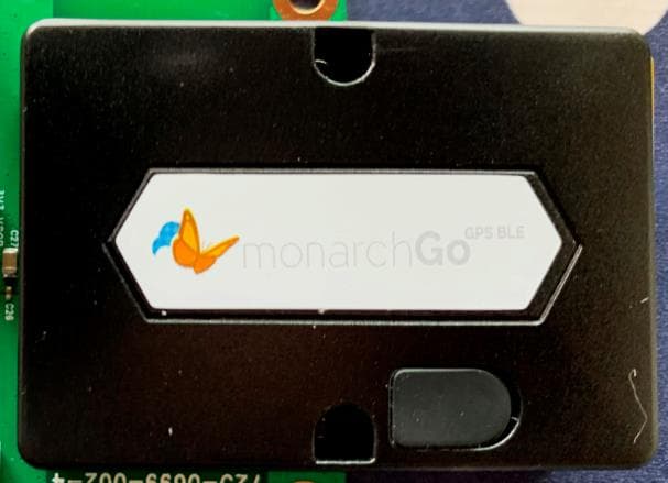
2AAGMGMQGOB
Nov 04, 2020Monarch Go-GPS BLE
Equipment Class
DTS - Digital Transmission System