2AAM3MP40DCSmart Phone
Bulltech Electronic Products S.L.
Click to zoom
Application Details
- Equipment Class
- DSS - Part 15 Spread Spectrum Transmitter
- Date of Grant
- Dec 29, 2013
- Application Purpose
- Original Equipment
- Date of Application
- Dec 29, 2013
- Equipment Note
- Smart Phone
- Frequency Range
- 2402.00000000 - 2480.00000000
- Country
- Spain
Documents & Files
Document Text
Text extracted from the exhibit documents filed with the FCC. Open a document above to read the original.
Users Manual
Smart Phone Model Name: Syreni 40DC Brand Name: Szenio FCC ID:2AAM3MP40DC CONTENT CONTENT CHAPTER CONTENT 1 INTRODUCTION About this user manual Notes for this manual Overview 2 GETTING STARTED Makes sure you have everything Charging battery Turning the device on or off Locking and unlocking the screen Using headset 3 LEARNING THE BASICS Home screen Extended home screen Shortcut icons Widgets 1 3 3 3 3 5 5 5 5 6 6 7 7 7 9 9 Wallpaper Application Text entry Contact Importing and exporting contact Communicating with contact Managing contact Favorite contact Using the phone 4 EMAIL & MESSAGING Text message Multimedia message Customizing message settings Email accounts Using email 5 INTERNET & BLUETOOTH Connecting to internet Browsing web page Using Bluetooth 6 MULTIMEDIA APPLICATIONS Videos and photos 9 10 11 12 12 13 13 14 14 16 16 17 17 18 19 22 22 23 23 25 25 1 CONTENT Viewing photos Using music player FM radio 7 PROGRAMS Backup and Restore Browser Calculator Calendar Camera Clock Contact Downloads Email Messaging Play music Gallery Phone Settings Video Player 8 MANAGING YOUR PHONE Device settings Changing basic settings 25 25 26 27 27 27 27 27 27 27 27 27 28 28 28 28 28 28 28 30 31 Using wireless & networks Protecting your phone Resetting the device APPENDIX Appendix : Safety information 32 33 33 34 35 2 INTRODUCTION 1.INTRODUCTION ABOUT THIS USER MANUAL You are reading the Smartphone User’s Manual. This User’s Manual provides information on the various components in the Smartphone and how to use them. NOTES FOR THIS MANUAL A few notes and warnings in bold are used throughout this guide that you should be aware of in order to complete certain tasks safely and completely. NOTES Tips and information for special situations OVERVIEW about the operating systems or programs then please consult the appropriate manuals. Operating system – Your Smartphone may already come with system software pre-installed. Where this is not the case, or where you are re-configuring your Smartphone for a different system, you will find this manual refers to the following operating systems: Android Jelly Bean What’s in the Box? Your package comes with the following items. If any of them is missing, please contact your retailer: This manual refers to the hardware and essential software required to run the Smartphone. Device AC Adapter USB Cable Not included – Operating System (e.g: Android Jelly Bean) have their own manuals. If you have questions 3 INTRODUCTION Battery NOTES Quick Start Guide Headset Actual accessories design may differ from what is represented this visual. 4 GETTING STARTED 2. GETTING STARTED NOTES MAKES SURE YOU HAVE EVERYTHING Before moving on the next set of instructions, make sure that you have received all items/components. If any items are missing and/or damaged, notify your dealer immediately (see “What’s in the Box” on chapter 1). CHARGING BATTERY The battery that came with your device is only partially charged. To fully charge the battery, charge it for 2 hours. Charge the battery 1. Connect one end of the AC adaptor to the Micro USB connector of the device. 2. Plug the other end of the AC adaptor to the wall outlet to start charging. Battery can also be charged when device connects to computer through USB cable. Battery life varies depending on network, applications, and ambient temperature. TURNING THE DEVICE ON or OFF After installing SIM card and charging battery, device is ready to turn on. Turn on your device Press and hold the power button. Turn off your device 1. Press and hold power button for 5 seconds. 2. A pop-up window appears, tap Power off. Set device to airplane mode 1. Press and hold the Power button for 5 seconds. 2. On the options menu, tap Airplane mode. 5 GETTING STARTED Set device to silent mode 1. Press and hold the Power button for 5 seconds. 2. Drag to the right of the screen to unlock the 2. On the options menu, tap . Set device to sleep mode To set the device to sleep mode, press the Power button. This turns the display off. To turn the display on, press the Power button again. LOCKING AND UNLOCKING THE SCREEN Lock the screen to prevent it from accidentally being touched. By default, the screen locks after being idle for a period of time (see “Display Settings” on chapter 8). Lock the screen To manually lock the screen and turn off the display, press the Power button. Unlock the screen 1. Press power button or front buttons to turn on the display from Sleep mode. 6 screen. USING HEADSET For hands-free conversation or listening to music, plug one headset to headset jack. NOTES When using headset, your ability to hear outside sounds may be limited. Do not use headset if it will endanger you. Do not set volume to maximum with headset as it may damage your hearing. LEARNING THE BASICS 3. LEARNING THE BASICS HOME SCREEN From Home screen, you can quickly access common features and view notifications of missed calls, receive messages and check connection status. EXTENDED HOME SCREEN Swipe your finger to the left or right across the home screen. The two extensions to the left and to the right of the Home screen provide more space for icons, widgets, shortcuts, and other items. Status bar The Status bar icons indicate different types of information. The following icons may appear on the status bar. No Icon 1 2 3 4 Battery icon No Icon 1 2 3 Description Sound is off Vibrate mode is activated Speakerphone is on Phone is muted Description Battery is full Battery is low Battery is charging Volume icons The following icons may appear on the volume icon area: 7 LEARNING THE BASICS Connection icon No Icon Description 3 Miss call notification 1 2 3 4 5 6 No network signal Maximum signal strength. Fewer bars indicate lower signal strength. GPRS network is in use. Wi-Fi is connected. Bluetooth connection is active. Device is connected to PC via USB connector 4 5 6 7 8 9 New text message notification. New email notification. New Google mail notification. Alarm. Task notif…
Text truncated - open the document above for the full version.
Cover Letter(s)
Dec. 21, 2013 Federal Communication Commission Authorization and Evaluation Division FCC ID: 2AAM3MP40DC Re: Confidentiality Request Pursuant to Sections 0.457 and 0.459 of the Commission’s Rules, the applicant hereby requests confidential treatment of information applied this application as outlined below: 1: Block Diagram 2: Circuit Diagram 3: Operational Description 4: Parts List 5: Turn Up Procedure The above materials contain trade secrets and proprietary information not customarily released to the public. The public disclosure of these matters might be harmful to the applicant and provide unjustified benefits to its competitors. The Applicant understands that pursuant to Rules 0.457, disclosure of this Application and all accompanying documentation will not be made before the date of the Grant for this application. Sincerely, Bulltech Electronic Products S.L. Contact person: Sonia Alvarez Title: Manager
Cover Letter(s)
Ersteller: D. Brandhorst Revision: 00 Erstelldatum: 21.06.07 Datum: 00.00.00 Seite 1 von 1 Date: Dec. 21, 2013 Subject: Ad Hoc Mode Function Declaration FCC ID: 2AAM3MP40DC To Whom it may concern, This device is acting as host device and operating in the 2.4 GHz (2412 – 2462 MHz) band. Ad Hoc function is supported but not able to operate on non-US frequencies. Please contact the one signed below or the authorized agent for this filing. Thank you. Regards, Bulltech Electronic Products S.L. Contact person: Sonia Alvarez Title: Manager
Cover Letter(s)
Bulltech Electronic Products S.L. Gran Via, 64, 2-I, 28013 Madrid, Spain. Date: Dec. 21, 2013 Statement We, Bulltech Electronic Products S.L. states that our device, FCC ID: 2AAM3MP40DC, has no space to put the label except the battery compartment of this device. It is visible to the users as they purchase the products and install the battery. Regards Company: Bulltech Electronic Products S.L. Contact Person: Sonia Alvarez Title: Manager
External Photos
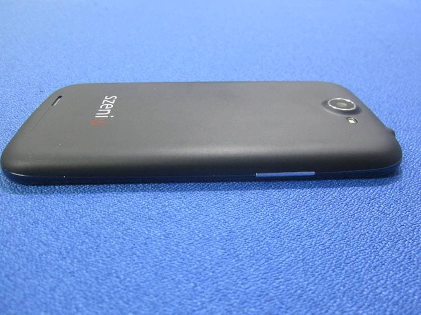
External Photos TOTAL VIEW OF EUT TOP VIEW OF EUT BOTTOM VIEW OF EUT FRONT VIEW OF EUT BACK VIEW OF EUT LEFT VIEW OF EUT RIGHT VIEW OF EUT
ID Label/Location Info
FCC ID Label Location Smart Phone Model: Syreni 40DC Trade Name: Szenio FCC ID: 2AAM3MP40DC
Internal Photos
Internal Photos OPEN VIEW OF EUT‐1 OPEN VIEW OF EUT‐2 GSM & WCDMA Antenna BT&WIFI &GPS Antenna OPEN VIEW OF EUT‐3 INTERNAL VIEW OF EUT‐1 INTERNAL VIEW OF EUT‐2
Test Report
Report No.: AGC01388131202FE03 Page 1 of 58 FCC Test Report Report No.: AGC01388131202FE03 FCC ID : 2AAM3MP40DC APPLICATION PURPOSE : Original Equipment PRODUCT DESIGNATION : Smart Phone BRAND NAME : Szenio MODEL NAME : Syreni 40DC CLIENT : Bulltech Electronic Products S.L. DATE OF ISSUE : Dec. 20, 2013 STANDARD(S) : FCC Part 15 Rules REPORT VERSION : V1.0 Attestation of Global Compliance (Shenzhen) Co., Ltd CAUTION: This report shall not be reproduced except in full without the written permission of the test laboratory and shall not be quoted out of context. Report No.: AGC01388131202FE03 Page 2 of 58 Report Revise Record Report Version Revise Time Issued Date Valid Version Notes V1.0 / Dec. 20, 2013 Valid Original Report Report No.: AGC01388131202FE03 Page 3 of 58 TABLE OF CONTENTS 1. VERIFICATION OF CONFORMITY ............................................................................................................ 5 2. GENERAL INFORMATION ........................................................................................................................ 6 2.1. PRODUCT DESCRIPTION ................................................................................................................. 6 2.2. TABLE OF CARRIER FREQUENCYS ................................................................................................ 6 2.3. RECEIVER INPUT BANDWIDTH ....................................................................................................... 7 2.4. EXAMPLE OF A HOPPING SEQUENCY IN DATA MODE .................................................................. 7 2.5. EQUALLY AVERAGE USE OF FREQUENCIES AND BEHAVIOUR ................................................... 7 2.6. RELATED SUBMITTAL(S) / GRANT (S) ............................................................................................. 8 2.7. TEST METHODOLOGY ...................................................................................................................... 8 2.8. SPECIAL ACCESSORIES .................................................................................................................. 8 2.9. EQUIPMENT MODIFICATIONS .......................................................................................................... 8 3. MEASUREMENT UNCERTAINTY ............................................................................................................. 9 4. DESCRIPTION OF TEST MODES ............................................................................................................. 9 5. SYSTEM TEST CONFIGURATION .......................................................................................................... 10 5.1. CONFIGURATION OF EUT SYSTEM ............................................................................................... 10 5.2. EQUIPMENT USED IN EUT SYSTEM .............................................................................................. 10 5.3. SUMMARY OF TEST RESULTS ....................................................................................................... 10 6. TEST FACILITY ........................................................................................................................................ 11 7. PEAK OUTPUT POWER .......................................................................................................................... 12 7.1. MEASUREMENT PROCEDURE ...................................................................................................... 12 7.2. TEST SET-UP (BLOCK DIAGRAM OF CONFIGURATION) ............................................................. 12 7.3. LIMITS AND MEASUREMENT RESULT ........................................................................................... 13 8. 20DB BANDWIDTH .................................................................................................................................. 19 8.1. MEASUREMENT PROCEDURE ...................................................................................................... 19 8.2. TEST SET-UP (BLOCK DIAGRAM OF CONFIGURATION) ............................................................. 19 8.3. LIMITS AND MEASUREMENT RESULTS ........................................................................................ 19 9. CONDUCTED SPURIOUS EMISSION ..................................................................................................... 26 9.1. MEASUREMENT PROCEDURE ...................................................................................................... 26 9.2. TEST SET-UP (BLOCK DIAGRAM OF CONFIGURATION) ............................................................. 26 9.3. MEASUREMENT EQUIPMENT USED ............................................................................................. 26 9.4. LIMITS AND MEASUREMENT RESULT ........................................................................................... 26 10. RADIATED EMISSION ........................................................................................................................... 30 10.1. MEASUREMENT PROCEDURE .................................................................................................... 30 10.2. TEST SETUP .................................................................................................................................. 32 Report No.: AGC01388131202FE03 Page 4 of 58 10.3. TEST RESULT ................................................................................................................................ 33 11. BAND EDGE EMISSION ........................................................................................................................ 37 11.1. MEASUREMENT PROCEDURE ..................................................................................................... 37 11.2. TEST SET-UP ................................................................................................................................. 3…
Text truncated - open the document above for the full version.
Test Setup Photos
Te s t Setup Photos CONDUCTED EMISSION RADIATED SPURIOUS EMISSION
Contact Information
Applicant
Sonia Alvarez
Test Firm
Attestation of Global Compliance Shenzhen Co. Ltd.Forrest Lei
Technical Specifications
| # | Rule Parts | Frequency Range | Power Output |
|---|---|---|---|
| 1 | 15C | 2.40 GHz - 2.48 GHz | 3.50 mW |
Other Applications from Bulltech Electronic Products S.L.
2AAM3SYRENI50DCII
Apr 20, 2014WCDMA+GSM SMART PHONE
Equipment Class
PCE - PCS Licensed Transmitter held to ear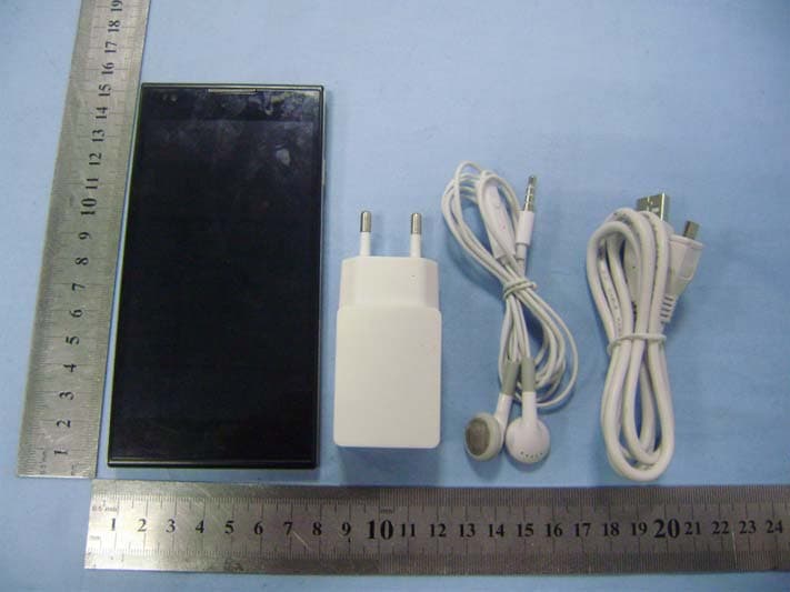
2AAM3SYRENI500
Jan 14, 2014MOBILE PHONE
Equipment Class
PCE - PCS Licensed Transmitter held to ear
2AAM3TAB70DC
Dec 21, 2013TABLET PC
Equipment Class
DTS - Digital Transmission System