2AAQQ52505332333030WIRELESS BIKE CADENCE SENSOR
TAIWAN BIOTRONIC TECHNOLOGY INC.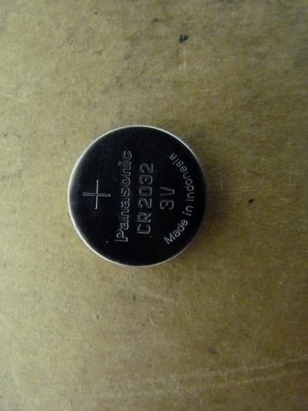
Click to zoom
Application Details
- Equipment Class
- DXX - Part 15 Low Power Communication Device Transmitter
- Date of Grant
- Sep 04, 2013
- Application Purpose
- Original Equipment
- Date of Application
- Sep 04, 2013
- Equipment Note
- WIRELESS BIKE CADENCE SENSOR
- Frequency Range
- 2402.00000000 - 2466.00000000
- Country
- Taiwan
Documents & Files
Document Text
Text extracted from the exhibit documents filed with the FCC. Open a document above to read the original.
Users Manual
Lifevisa WIRELESS BIKE CADENCE SENSOR [RPS-2300] USER MANUAL COMPONENTS 1. Cadence Sensor with Screw, Nut & Foam Pad 2. O-Ring 3. 3V CR2032 Lithium Battery 4. Battery Cover 5. Zip Tie for Cadence Sensor X 2pcs 6. Zip Tie for Cadence Magnet X 2pcs 7. Cadence Magnet with Screw & Nut 2.4GHz CADENCE SENSOR BATTERY INSTALLMENT This Cadence Sensor includes a 3V CR2032 lithium battery. Please follow below steps to install the battery. Step 1. Insert the battery (CR2032) with the positive (+) side up. ☆ Make sure the battery is hooked by the contact spring. Step 2. Put on the O-Ring in the groove to ensure water resistance. ☆ Make sure to place the O-Ring properly in order to prevent battery composition from being spoiled by rain or water. Step 3. Place the battery cover and use a coin to twist it clockwise until it is tight enough. NOTE: ☆ Open the battery cover only when changing the battery to ensure a long life, and make sure the O-Ring is not damaged, in which case you should replace it with a new one. ☆ Keep battery away from children. If swallowed, contact a physician at Thank you for purchasing Lifevisa products. This manual contains information required to use Cadence Sensor. Please read this manual thoroughly before you use the Cadence Sensor. 123 7 5 & 64 1 2 ☆The effective distance/range is within 10 meters. Be sure no other devices are within this distance making the same approach. HOST CONNECTION This Cadence Sensor must be recognized to the host before being used for the first time. We recommend making this approach before installment. Please follow below instructions to complete the connection. 1. Turn on the host and enter connection mode. The host will wait the signal for 1 minute. If not receiving the signal, the host will exist the connection mode automatically. 2. Press the set key of Cadence Sensor. Then wait for connection. 3 3. The host should begin to display a reading, showing the connection has been done and you can start to install the Cadence Sensor and Magnet. set key 2.4GHz Connection done!! For the latest version of this user manual and more product information, please visit our website at http://www.biotronic.com.tw NOTE: ☆ This step only has to be done at the first time of use with the same Cadence Sensor and host. Afterwards, even changing battery, you don't need to reconnect to the host. ☆ See TROUBLESHOOTING AND CARE section if you are experiencing connection issues. The Bike Cadence Sensor measures and sends your pedaling strokes per minute information to the host. Please follow the simple instructions below to mount the Cadence on your bike. 1. Find an appropriate position and place the Cadence Magnet to inner side of the crank arm. The Magnet should face toward down tube or chain stay. 2. Pass 2 zip ties over the Cadence Magnet and tighten them. Carefully snug 2 zip ties and trim the excess. Make sure the Magnet is mounted To install Cadence Magnet and Cadence Sensor, you need cutters and cross-head screwdrivers. Before installment, clean and dry the position of the device. 4 3. Place the Cadence Sensor on the down tube or chain stay. The position of Cadence Sensor should be corresponded to Magnet's. There is an indication line on the top of the Sensor, which limits the effective range that the Magnet could pass through. Align the Magnet to the center of 5. Remove the adhesive of foam pad from Cadence Sensor and attach the Cadence Sensor to the marked position on the down tube or chain stay. 6. Pass 2 zip ties over the Cadence Sensor and tighten them. Carefully snug 2 zip ties and trim the excess. Make sure the Cadence Sensor is mounted securely. 4. Sensor's logo is toward you and you can adjust Sensor's angle to find the suitable gap. Remember that the best gap between Cadence Sensor and Magnet is about 4mm (0.16"). Pedal to test the alignment of Sensor and 5 TROUBLESHOOTING AND CARE Troubleshooting of the Cadence Sensor ● If you are not getting a good connection to the host, please (a) Make sure the position of the Sensor to the Magnet is installed correctly. (b) Make sure the gap between the Sensor and Magnet is appropriate. (c) Check if the battery is installed properly or change a new battery. (d) Repeat HOST CONNECTION section. ● The effective range of the whole system is 3 meters. If the host is away 7. Fine-tune the angle of Cadence Sensor to ensure the Magnet can pass as close to the Sensor as possible but does not touch it. The gap between the Sensor and the Magnet should be 4mm (0.16"). Finally, tighten the screw on the Sensor with a screwdriver. NOTE: ☆ If you have done host connection before installment, make sure you do not touch the set key accidentally; otherwise, please repeat HOST CONNECTION section. Care of the Cadence Sensor and Magnet ● Keep the Cadence Sensor and Magnet clean after every use. ● Keep the Cadence Sensor and Magnet out of extremely cold and hot. We care about your safety. Make sure the device is not against any parts of your bike and to avoid being heavily hit during cycling as it may damage the Sensor. 6 HOW TO INSTALL THE CADENCE HOW TO INSTALL THE CADENCEHOW TO INSTALL THE CADENCE indication line effective range Federal Communication Commission Interference Statement This equipment has been tested and found to comply with the limits for a Class B digital device, pursuant to Part 15 of the FCC Rules. These limits are designed to provide reasonable protection against harmful interference in a residential installation. This equipment generates, uses and can radiate radio frequency energy and, if not installed and used in accordance with the instructions, may cause harmful interference to radio communications. However, there is no guarantee that interference will not occur in a particular installation. If this equipment does cause harmful interference to radio or television reception, which can be determined by turning the equipment off and on, the user is encouraged to try to correct the interference by one of the follow…
Text truncated - open the document above for the full version.
Cover Letter(s)
Taiwan Biotronic Technology Inc. 20 Lane 53 Hua Cheng Street, Da Li Dist., Taichung Hsien 41247 Taiwan Federal Communications Commission Authorization and Evaluation Division Equipment Authorization Branch 7435 Oakland Mills Road Columbia, MD 21046 Date: 15.08.2013 To whom it may concern: We, the undersigned, hereby authorize Worldwide Testing Services (Taiwan) Co., Ltd to act on our behalf in all matters relating to applications for equipment authorization FCC ID: 2AAQQ52505332333030 including the signing of all documents related to these matters. Any and all acts carried out by Worldwide Testing Services (Taiwan) Co., Ltd on our behalf shall have the same effect as acts of our own. We also hereby certify that no party to this application is subject to a denial of benefits, including FCC benefits, pursuant to Section 5301 of the Anti-Drug Abuse Act of 1988, 21 U.S.C. 862. Sincerely, Signature Name: Keven Su Title: Manager Company: Taiwan Biotronic Technology Inc.
Cover Letter(s)
Taiwan Biotronic Technology Inc. 20 Lane 53 Hua Cheng Street, Da Li Dist., Taichung Hsien 41247 Taiwan Federal Communications Commission Equipment Authorization Branch 7435 Oakland Mills Road Columbia, MD 21046 Date: 15.08.2013 Request for Confidentiality Company name: Taiwan Biotronic Technology Inc. FCC ID: 2AAQQ52505332333030 FCC Part 15 Certification To whom it may concern: In accordance with 0.459 of CFR 47, Taiwan Biotronic Technology Inc. hereby requests confidentiality of all Block Diagrams, Schematics, Operational Description attachments for the subject application. These documents contain detailed system and equipment description and related information about the product which Taiwan Biotronic Technology Inc. considers to be proprietary, confidential and a custom design and otherwise would not release to the general public. Since the design is a basis from which future technological products will evolve, Taiwan Biotronic Technology Inc. considers that this information would be of benefit to its competitors and that the disclosure of the information in these documents would give competitors an unfair advantage in the market. Sincerely, Signature Name: Keven Su Title: Manager Company: Taiwan Biotronic Technology Inc.
External Photos
Registration number: W6M21307-13371-FCC FCC ID: 2AAQQ52505332333030 Worldwide Testing Services(Taiwan) Co., Ltd. Appendix page 2 of 16 External Photos Registration number: W6M21307-13371-FCC FCC ID: 2AAQQ52505332333030 Worldwide Testing Services(Taiwan) Co., Ltd. Appendix page 3 of 16 Registration number: W6M21307-13371-FCC FCC ID: 2AAQQ52505332333030 Worldwide Testing Services(Taiwan) Co., Ltd. Appendix page 4 of 16 Registration number: W6M21307-13371-FCC FCC ID: 2AAQQ52505332333030 Worldwide Testing Services(Taiwan) Co., Ltd. Appendix page 5 of 16 Registration number: W6M21307-13371-FCC FCC ID: 2AAQQ52505332333030 Worldwide Testing Services(Taiwan) Co., Ltd. Appendix page 6 of 16
ID Label/Location Info
Model: RPS-2300 FCC ID: 2AAQQ52505332333030
Internal Photos
Registration number: W6M21307-13371-FCC FCC ID: 2AAQQ52505332333030 Worldwide Testing Services(Taiwan) Co., Ltd. Appendix page 7 of 16 Internal Photos Registration number: W6M21307-13371-FCC FCC ID: 2AAQQ52505332333030 Worldwide Testing Services(Taiwan) Co., Ltd. Appendix page 8 of 16 Registration number: W6M21307-13371-FCC FCC ID: 2AAQQ52505332333030 Worldwide Testing Services(Taiwan) Co., Ltd. Appendix page 9 of 16 Registration number: W6M21307-13371-FCC FCC ID: 2AAQQ52505332333030 Worldwide Testing Services(Taiwan) Co., Ltd. Appendix page 10 of 16 Registration number: W6M21307-13371-FCC FCC ID: 2AAQQ52505332333030 Worldwide Testing Services(Taiwan) Co., Ltd. Appendix page 11 of 16 Multi-listing model no.: SPS-2400 Registration number: W6M21307-13371-FCC FCC ID: 2AAQQ52505332333030 Worldwide Testing Services(Taiwan) Co., Ltd. Appendix page 12 of 16 Registration number: W6M21307-13371-FCC FCC ID: 2AAQQ52505332333030 Worldwide Testing Services(Taiwan) Co., Ltd. Appendix page 13 of 16
Test Report
of Applicant: Taiwan Biotronic Technology Inc. Address: 20 Lane 53 Hua Cheng Street, Da Li Dist., Taichung Hsien 41247 Taiwan Tested and Prepared by Worldwide Testing Services (Taiwan) Co., Ltd. FCC Registration No.: 930600 Industry Canada filed test laboratory Reg. No. IC 5679A-1 A2LA Accredited No.: 2732.01 Report No.: W6M21307-13371-C-1 6F, NO. 58, LANE 188, RUEY-KUANG RD., NEIHU TAIPEI 114, TAIWAN, R.O.C. TEL: 886-2-66068877 FAX: 886-2-66068879 E-mail: [email protected] FCC PART 15 SUBPART C TEST REPORT for WIRELESS BIKE CADENCE SENSOR Model No.: RPS-2300 FCC ID: 2AAQQ52505332333030 Registration number: W6M21307-13371-C-1 FCC ID: 2AAQQ52505332333030 Worldwide Testing Services(Taiwan) Co., Ltd. Page 1 of 22 TABLE OF CONTENTS 1 GENERAL INFORMATION ..........................................................................................................2 1.1 NOTES..........................................................................................................................................2 1.2 TESTING LABORATORY................................................................................................................3 1.2.1 Location ..............................................................................................................................3 1.2.2 Details of accreditation status ............................................................................................3 1.3 DETAILS OF APPROVAL HOLDER...................................................................................................3 1.4 APPLICATION DETAILS.................................................................................................................4 1.5 GENERAL INFORMATION OF TEST ITEM........................................................................................4 1.6 T EST STANDARDS.........................................................................................................................4 2 TECHNICAL TEST .........................................................................................................................5 2.1 SUMMARY OF TEST RESULTS........................................................................................................5 2.2 T EST ENVIRONMENT....................................................................................................................5 2.3 TEST EQUIPMENT LIST.................................................................................................................6 2.4 GENERAL TEST PROCEDURE........................................................................................................8 3 TEST RESULTS (ENCLOSURE) ..................................................................................................9 3.1 P EAK OUTPUT POWER (TRANSMITTER) ......................................................................................10 3.2 EQUIVALENT ISOTROPIC RADIATED POWER................................................................................11 3.3 RF EXPOSURE COMPLIANCE REQUIREMENTS............................................................................11 3.4 O UT OF BAND RADIATED EMISSIONS.........................................................................................12 3.5 SPURIOUS EMISSION (TX) ...........................................................................................................13 3.6 R ADIATED EMISSIONS FROM DIGITAL PART..............................................................................16 3.7 RADIATED EMISSION ON THE BAND EDGE..................................................................................17 3.8 P OWER LINE CONDUCTED EMISSION.........................................................................................21 A PPENDIX..................................................................................................................................................22 Registration number: W6M21307-13371-C-1 FCC ID: 2AAQQ52505332333030 Worldwide Testing Services(Taiwan) Co., Ltd. Page 2 of 22 1 General Information 1.1 Notes The purpose of conformity testing is to increase the probability of adherence to the essential requirements or conformity specifications, as appropriate. The complexity of the technical specifications, however, means that full and thorough testing is impractical for both technical and economic reasons. Furthermore, there is no guarantee that a test sample which has passed all the relevant tests conforms to a specification. Neither is there any guarantee that such a test sample will interwork with other genuinely open systems. The existence of the tests nevertheless provides the confidence that the test sample possesses the qualities as maintained and that is performance generally conforms to representative cases of communications equipment. The test results of this test report relate exclusively to the item tested as specified in 1.5. The test report may only be reproduced or published in full. Reproduction or publication of extracts from the report requires the prior written approval of the Worldwide Testing Services(Taiwan) Co., Ltd. Tester: August 26, 2013 Rick Chen Date WTS-Lab. Name Signature Technical responsibility for area of testing: August 26, 2013 Kevin Wang Date WTS Name Signature Registration number: W6M21307-13371-C-1 FCC ID: 2AAQQ52505332333030 Worldwide Testing Services(Taiwan) Co., Ltd. Page 3 of 22 1.2 Testing laboratory 1.2.1 Location OATS No.5-1, Lishui, Shuang Sing Village, Wanli Dist., New Taipei City 207, Taiwan (R.O.C.) 3 meter semi-anechoic chamber No.35, Aly. 21, Ln. 228, Ankang Rd., Neihu Dist., Taipei City 114, Taiwan (R.O.C.) TEL:886-2-6613-0228 FAX:886-2-2791-5046 Company Worldwide Testing Services(Taiwan) Co., Ltd. 6F, NO. 58, LANE 188, RUEY-KUANG RD. NEIHU, TAIPEI 114, TAIWAN R.O.C. Tel : 886-2-66068877 Fax : 886-2-66068879 1.2.2 Details of accreditation status Accredited testing laboratory A2LA accredited number: 2730.01 FCC filed test laboratory…
Text truncated - open the document above for the full version.
Test Setup Photos
Registration number: W6M21307-13371-FCC FCC ID: 2AAQQ52505332333030 Worldwide Testing Services(Taiwan) Co., Ltd. Appendix page 14 of 16 Set Up Photo of Radiated Emission Below 1GHz Registration number: W6M21307-13371-FCC FCC ID: 2AAQQ52505332333030 Worldwide Testing Services(Taiwan) Co., Ltd. Appendix page 15 of 16 Above 1GHz Registration number: W6M21307-13371-FCC FCC ID: 2AAQQ52505332333030 Worldwide Testing Services(Taiwan) Co., Ltd. Appendix page 16 of 16 RF
Contact Information
Applicant
Keven Su(Manager)
Technical Contact
Worldwide Testing Services (Taiwan) Co., Ltd.Tse-Ming Chang
[email protected]+886-2-6606-8877
6F., No. 58, Lane 188, Ruey Kuand Rd. · Taipei · Taiwan
Test Firm
Worldwide Testing Services (Taiwan) Co., Ltd.Rex Kao
Technical Specifications
| # | Rule Parts | Frequency Range | Power Output |
|---|---|---|---|
| 1 | 15C | 2.40 GHz - 2.47 GHz | - |
Other Applications from TAIWAN BIOTRONIC TECHNOLOGY INC.
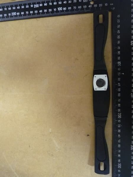
2AAQQ48525332323030
Sep 02, 2013WIRELESS HEART RATE TRANSMITTER
Equipment Class
DXX - Part 15 Low Power Communication Device Transmitter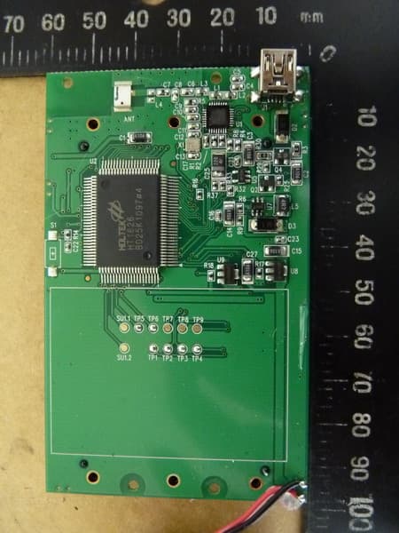
2AAQQ4C563230303041
Sep 01, 2013WIRELESS CYCLE COMPUTER
Equipment Class
DXX - Part 15 Low Power Communication Device Transmitter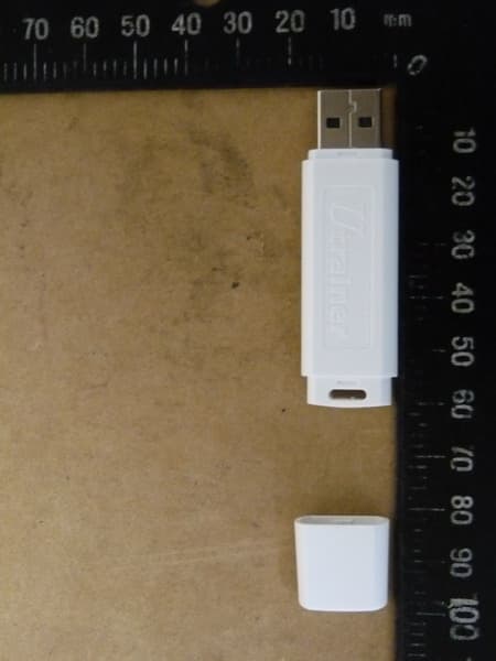
2AAQQ44424832303030
Sep 01, 2013USB dongle
Equipment Class
DXX - Part 15 Low Power Communication Device Transmitter