2AASRB3329BBLE tag
THLight Co. Ltd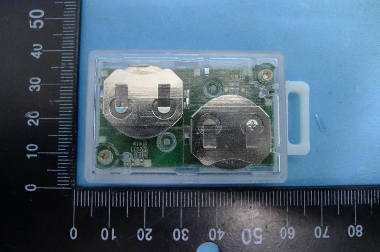
Click to zoom
Application Details
- Equipment Class
- DTS - Digital Transmission System
- Date of Grant
- May 20, 2020
- Application Purpose
- Original Equipment
- Date of Application
- May 19, 2020
- Equipment Note
- BLE tag
- Frequency Range
- 2402.00000000 - 2480.00000000
- Company
- THLight Co. Ltd
- Country
- Taiwan
Documents & Files
Document Text
Text extracted from the exhibit documents filed with the FCC. Open a document above to read the original.
Users Manual
Search for “USBeacon Writer” from Google Play or enter the following url: https://play.google.com/store/apps/details?id=com.THLight.BLE.USBeacon.Writer.Simple&hl=en 1. Download “USBeacon Writer” onto your smartphone or tablet with Android 4.3 or above. 2. Create an account and log into the USBeacon erver for the first time. If this is your first time using the USBeacon Writer App, please create an account by hitting the “Create New Account” button. If you would like to log in with Facebook account, please go to: www.usbeacon.com.tw/console/index.html and select Facebook login to link your Facebook account to your new USBeacon account. If you chose to create your account with Face- book login and have the Facebook App installed on your smart device, user name and password will not be required to log in. All you need to do is hit the “Login with Facebook” button to enter the system. After you have created your account, enter your user name and password to log into server. If your smart device is accessible only by autho- rized personnel, you may check the “Remember Me” check box to save time in the future. USBeacon USER MANUAL FOR ANDROID PLATFORM Pg 01 / 06 ©2015 THLight Co. Inc. 3. Detected Beacon List. After a successful login, immediately follows the detected beacon list page. This page shows all the BLE devices detected in current environment. Make sure the targeted beacon is on, and if possible, switch off other bluetooth devices to avoid confusion. BACK / Returns to login page. REFRESH / Refreshes the detected beacon list. RSSI Value / Always negative, beacon with value- closest to 0 is closest to you. HELP / INFORMATION BOX / Provides user guide or information on current page, can be hidden or unhidden with the up/down arrow. Select the beacon that you wish to configure from list to enter setup screen. USBeacon USER MANUAL FOR ANDROID PLATFORM Pg 02 / 06 ©2015 THLight Co. Inc. 4. Creating new beacon profile or link profiles to beacon. Once you have selected a beacon to proceed with setup, there are minor differences as to what to do next depending on the status of the beacon: If you have not used the server to create beacon profiles already, choose “Create New Beacon” to enter setup to create your beacon’s profile. If you have used the server to create beacon profiles already, the profiles will show up under the Create New Beacon tab (requires internet connection to sync profiles from server). Select the desired profile to make a link from profile to beacon. Beacon Config / You will reach this page either by the A or B route above. Or, if your beacon has been configured previously, upon your selection from the “Beacons Detected” page, the system will automatically jump to this page since your beacon has already been linked to a profile. USBeacon USER MANUAL FOR ANDROID PLATFORM Pg 03 / 06 ©2015 THLight Co. Inc. USBeacon USER MANUAL FOR ANDROID PLATFORM Pg 04 / 06 ©2015 THLight Co. Inc. 5. Beacon Configuration - Beacon Information Once you have selected a beacon to proceed with setup, there are minor differences as to what to do next depending on the status of the beacon: NAME / User may name each beacon freely as a reminder of its function or location; name must be within 24 characters. MAC / Obtained from beacon itself; cannot be changed. UUID / Obtained from server end; cannot be changed. MAJOR & MINOR / Can be values anywhere from 0 ~ 65535. Indicates that beacon is powered by battery; remaining battery life is represented with bars (3 = full). Indicates that beacon is powered by USB. NOTES / Allows user to enter any notes (function not activated yet as of 2015.08, coming soon). RESET TO FACTORY SETTINGS / Restore all beacon settings back to factory settings. *Warning: Customized settings will not be able to be restored once a beacon is reset. SAVE CHANGES / Saves all changes made and reboots beacon. BACK / Returns to “Beacons Detected” page without saving any changes made. USBeacon USER MANUAL FOR ANDROID PLATFORM Pg 05 / 06 ©2015 THLight Co. Inc. 6. Beacon Configuration - Power Management While the beacon will function fine with factory power settings, changing its power settings according to your specific needs will allow the beacon to work with optimal efficiency. BACK / Returns to “Beacons Detected” page without saving any changes made. Tx Power / Allows user to adjust signal strength; more energy (shorter battery life) is required for stronger signals. Broadcast Frequency / User may use either X times per second or X milliseconds per broad- cast to change beacon’s broadcast frequency; more energy (shorter battery life) is required for more frequent broadcasting. (Min = 1, Max = 30, times per sec.) BLE Mode / This setting is for previous beacon models only; it is disabled automatically if you are running a new version beacon. Old beacons will not immediately begin its broadcast once switched on. Instead, it stays in BLE mode for a period of time dictated by the power management setting here. During this time, the beacon is open for connection to your smart device. After this period of time, the beacon will return to broadcast mode and changes will not be possible. To enter BLE mode, please manually switch beacon off and on again. REMAINING BATTERY LIFE / This is an estimated remaining battery life calculated with power settings above. It serves to help user in assess- ing the type of the power settings that is most efficient. When calibration is complete, use the “Set RSSI” button at the bottom right to set new RSSI value as RSSI Value at 1 meter. Be sure to save changes in the main Calibration UI when pop screen is closed. If there were any abnormal interference or if the placement of smart device is incorrect in anyway, hit “Start Over” to calibrate RSSI again. 7. Beacon Configuration - Calibration USBeacon USER MANUAL FOR ANDROID PLATFORM Pg 06 / 06 ©2015 THLight Co. Inc. iBeacons have many useful applications, and most of these applications will require accurate RSSI-to…
Text truncated - open the document above for the full version.
External Photos
Report No.: 2004TW1101-U2 Product: BLE tag Brand Name: THLight Model Number: USBeacon B3329B 1 of 3 External Photograph (1) EUT Photo (2) EUT Photo Report No.: 2004TW1101-U2 2 of 3 (3) EUT Photo (4) EUT Photo Report No.: 2004TW1101-U2 3 of 3 (5) EUT Photo (6) EUT Photo
ID Label/Location Info
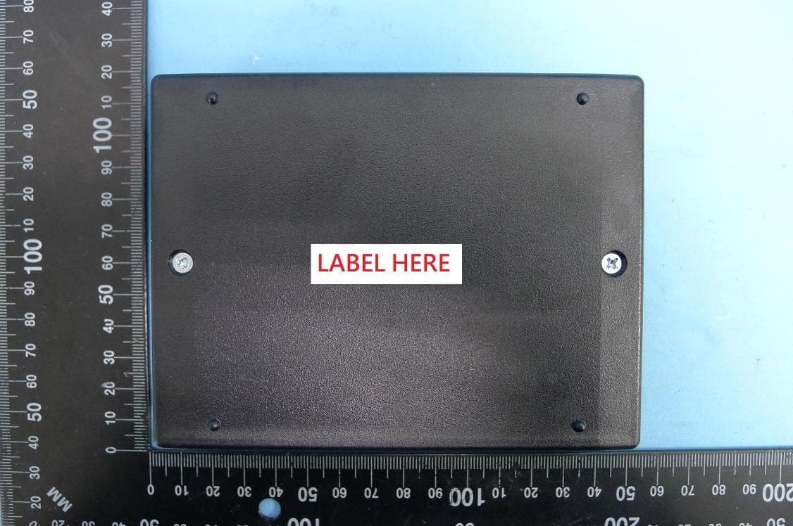
Label Label location
Internal Photos
Report No.: 2004TW1101-U2 Product: BLE tag Brand Name: THLight Model Number: USBeacon B3329B 1 of 2 Internal Photograph (1) EUT Photo (2) EUT Photo Report No.: 2004TW1101-U2 2 of 2 (3) EUT Photo (4) EUT Photo
RF Exposure Info
05 MRT Technology (Taiwan) Co., Ltd Report No.: 2004TW1101-U3 Phone: +886-3-3288388 Report Version: 1.0 Fax: +886-3-3288918 Issue Date: 2020-05-05 Web: www.mrt-cert.com FCC ID: 2AASRB3329B Page Number: 1 of 6 RF Exposure Evaluation Declaration FCC ID: 2AASRB3329B APPLICANT: THLight Co. Ltd Application Type: Certification Product: BLE tag Model No.: USBeacon B3329B Trademark: FCC Rule Part(s): Part 2.1093 (Portable) Test Procedure(s): KDB 447498 D01v06 Test Date: March 20 ~ April 14, 2020 Reviewed By : ( Paddy Chen ) Approved By : ( Chenz Ker ) The test results relate only to the samples tested. The test results shown in the test report are traceable to the national/international standards through the calibration of the equipment and evaluated measurement uncertainty herein. The test report shall not be reproduced except in full without the written approval of MRT Technology (Taiwan) Co., Ltd. Report No.: 2004TW1101-U3 FCC ID: 2AASRB3329B Page Number: 2 of 6 Revision History Report No. Version Description Issue Date Note 2004TW1101-U3 1.0 Original Report 2020-05-05 Report No.: 2004TW1101-U3 FCC ID: 2AASRB3329B Page Number: 3 of 6 1. PRODUCT INFORMATION 1.1. Equipment Description 1.2. Antenna Description No. Manufacturer Part No. Antenna Type Peak Gain 1 RIMON TECHNOLOGY CO., LTD WAN3216F245C0X Chip 1.75dBi Product Name BLE tag FCC ID 2AASRB3329B Model No. USBeacon B3329B Trademark Supports Radios Spec. Bluetooth V4.2 Bluetooth Specification V4.2 LE Operating Frequency 2402~2480MHz Type of modulation GFSK Report No.: 2004TW1101-U3 FCC ID: 2AASRB3329B Page Number: 4 of 6 2. RF Exposure Evaluation 2.1. FCC Limits According to FCC KDB 447498 Section 4.3 - General SAR test exclusion guidance For 100 MHz to 6 GHz and test separation distances ≤ 50 mm, the 1-g and 10-g SAR test exclusion thresholds are determined by the following: [(max. power of channel, including tune-up tolerance, mW) / (min. test separation distance, mm)] · [√f(GHz)] ≤ 3.0 for 1-g SAR, and ≤ 7.5 for 10-g extremity SAR, where 1. f(GHz) is the RF channel transmit frequency in GHz 2. Power and distance are rounded to the nearest mW and mm before calculation 3. The result is rounded to one decimal place for comparison 4.The values 3.0 and 7.5 are referred to as numeric thresholds in step b) below The test exclusions are applicable only when the minimum test separation distance is ≤ 50 mm, and for transmission frequencies between 100 MHz and 6 GHz. When the minimum test separation distance is < 5 mm, a distance of 5 mm according to 4.1 f) is applied to determine SAR test exclusion. 2.2. IC Limits Output power level shall be the higher of the maximum conducted or equivalent isotropically radiated power (e.i.r.p.) source-based, time-averaged output power. For controlled use devices where the 8 W/kg for 1 gram of tissue applies, the exemption limits for routine evaluation in Table 1 are multiplied by a factor of 5. For limb-worn devices where the 10 gram value applies, the exemption limits for routine evaluation in Table 1 are multiplied by a factor of 2.5. If the operating frequency of the device is between two frequencies located in Table 1, linear interpolation shall be applied for the applicable separation distance. For test separation distance less than 5 mm, the exemption limits for a separation distance of 5 mm can be applied to determine if a routine evaluation is required. Report No.: 2004TW1101-U3 FCC ID: 2AASRB3329B Page Number: 5 of 6 Frequency (MHz) Exemption Limits (mW) At separation distance of ≤5 mm At separation distance of 10 mm At separation distance of 15 mm At separation distance of 20 mm At separation distance of 25 mm 300 71 mW 101 mW 132 mW 162 mW 193 mW 450 52 mW 70 mW 88 mW 106 mW 123 mW 835 17 mW 30 mW 42 mW 55 mW 67 mW 1900 7 mW 10 mW 18 mW 34 mW 60 mW 2450 4 mW 7 mW 15 mW 30 mW 52 mW 3500 2 mW 6 mW 16 mW 32 mW 55 mW 5800 1 mW 6 mW 15 mW 27 mW 41 mW Frequency (MHz) At separation distance of 30 mm At separation distance of 35 mm At separation distance of 40 mm At separation distance of 45 mm At separation distance of ≥50 mm ≤300 223 mW 254 mW 284 mW 315 mW 345 mW 450 141 mW 159 mW 177 mW 195 mW 213 mW 835 80 mW 92 mW 105 mW 117 mW 130 mW 1900 99 mW 153 mW 225 mW 316 mW 431 mW 2450 83 mW 123 mW 173 mW 235 mW 309 mW 3500 86 mW 124 mW 170 mW 225 mW 290 mW 5800 56 mW 71 mW 85 mW 97 mW 106 mW Table 1: SAR evaluation – Exemption limits for routine evaluation based on frequency and separation distance. Report No.: 2004TW1101-U3 FCC ID: 2AASRB3329B Page Number: 6 of 6 2.3. Test Result of RF Exposure Evaluation Mode Frequency Band (MHz) Output Power (dBm) Output Power (mW) Test Exclusion Threshold (mW) BLE 2402~2480 3.707 2.35 23.81 So, this device can complies the SAR test exclusion. The End
Test Report
MRT Technology (Taiwan) Co., Ltd Report No.: 2004TW1101-U2 Phone: +886-3-3288388 Report Version: 1.0 Fax: +886-3-3288918 Issue Date: 2020-05-05 Web: www.mrt-cert.com FCC ID: 2AASRB3329B Page Number: 1 of 50 FCC ID: 2AASRB3329B APPLICANT: THLight Co. Ltd Application Type: Certification Product: BLE tag Model No.: USBeacon B3329B Trademark: FCC Classification: (DTS) Digital Transmission System FCC Rule Part(s): Part 15.247 Test Procedure(s): ANSI C63.10-2013, KDB 558074 D01v05r02 Received Date: March 20, 2020 Test Date: March 20 ~ April 14, 2020 MEASUREMENT REPORT FCC PART 15.247 Bluetooth V4.1 LE The test results only relate to the tested sample. This equipment has been shown to be capable of compliance with the applicable technical standards as indicated in the measurement report and was tested in accordance with the measurement procedures specified in ANSI C63.4-2014. Test results reported herein relate only to the item(s) tested. The test report shall not be reproduced except in full without the written approval of MRT Technology (Taiwan) Co., Ltd. Tested By : ( Peter Syu ) Reviewed By : ( Paddy Chen ) Approved By : ( Chenz Ker) Report No.: 2004TW1101-U2 FCC ID: 2AASRB3329B Page Number: 2 of 50 Revision History Report No. Version Description Issue Date Note 2004TW1101-U2 1.0 Original Report 2020-05-05 Report No.: 2004TW1101-U2 FCC ID: 2AASRB3329B Page Number: 3 of 50 CONTENTS Description Page §2.1033 General Information ......................................................................................................... 5 1. INTRODUCTION ..................................................................................................................... 6 1.1. Scope .................................................................................................................................... 6 1.2. MRT Test Location ................................................................................................................ 6 2. PRODUCT INFORMATION ..................................................................................................... 7 2.1. Equipment Description .......................................................................................................... 7 2.2. Product Specification Subjective to this Standard .................................................................. 7 2.3. Test Mode ............................................................................................................................. 7 2.4. Operation Frequency / Channel List ...................................................................................... 8 2.5. Test Configuration ................................................................................................................. 9 2.6. Test Software ........................................................................................................................ 9 2.7. EMI Suppression Device(s)/Modifications ............................................................................. 9 2.8. Labeling Requirements ......................................................................................................... 9 3. DESCRIPTION of TEST ........................................................................................................ 10 3.1. Evaluation Procedure .......................................................................................................... 10 3.2. AC Line Conducted Emissions ............................................................................................ 10 3.3. Radiated Emissions ............................................................................................................ 11 4. ANTENNA REQUIREMENTS ................................................................................................ 12 5. TEST EQUIPMENT CALIBRATION DATE ............................................................................ 13 6. MEASUREMENT UNCERTAINTY ......................................................................................... 14 7. TEST RESULT ...................................................................................................................... 15 7.1. Summary ............................................................................................................................. 15 7.2. 6dB Bandwidth Measurement ............................................................................................. 16 7.2.1. Test Limit ......................................................................................................................... 16 7.2.2. Test Procedure used ....................................................................................................... 16 7.2.3. Test Setting ..................................................................................................................... 16 7.2.4. Test Setup ....................................................................................................................... 16 7.2.5. Test Result ...................................................................................................................... 17 7.3. Output Power Measurement ................................................................................................ 18 7.3.1. Test Limit ......................................................................................................................... 18 7.3.2. Test Procedure Used ....................................................................................................... 18 7.3.3. Test Setting ..................................................................................................................... 18 7.3.4. Test Setup ....................................................................................................................... 18 7.3.5. Test Result of Output Power ............................................................................................ 19 7.4. Po…
Text truncated - open the document above for the full version.
Test Setup Photos
Report No.: 2004TW1101-U2 Product: BLE tag Brand Name: THLight Model Number: USBeacon B3329B 1 of 3 Test Photograph Test Mode 1 Description: Front View of Conducted Emission Test Setup Test Mode 1 Description: Back View of Conducted Emission Test Setup Report No.: 2004TW1101-U2 2 of 3 Test Mode: Mode 1 Description: Radiated Emission Test Setup for below 1GHz Test Mode: Mode 1 Description: Radiated Emission Test Setup for above 1GHz Report No.: 2004TW1101-U2 3 of 3 Test Mode: Mode 1 Description: Conducted Emission Test Setup
Contact Information
Applicant
CJ Chi
Technical Contact
MRT Technology (Taiwan) Co., LtdChenz Ker
[email protected]886-3-3288388
No. 38, Fuxing Second Rd., Guishan Dist., · Taiwan
Non-Technical Contact
MRT Technology (Taiwan) Co., LtdChenz Ker
[email protected]886-3-3288388
Test Firm
MRT Technology (Taiwan) Co.,LtdChenz Ker
Technical Specifications
| # | Rule Parts | Frequency Range | Power Output |
|---|---|---|---|
| 1 | 15C | 2.40 GHz - 2.48 GHz | 2.30 mW |
Other Applications from THLight Co. Ltd
2AASRW8010R
May 25, 2020SENTINEL
Equipment Class
DTS - Digital Transmission System
2AASRIREEMO2
Jul 06, 2014iReemo2
Equipment Class
DTS - Digital Transmission System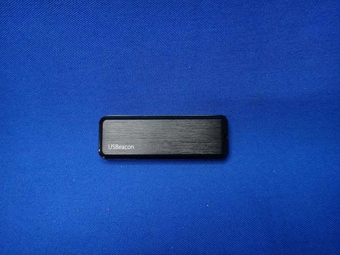
2AASRIREEMOPLUS
Jun 22, 2014iReemo+, usbeacon
Equipment Class
DTS - Digital Transmission System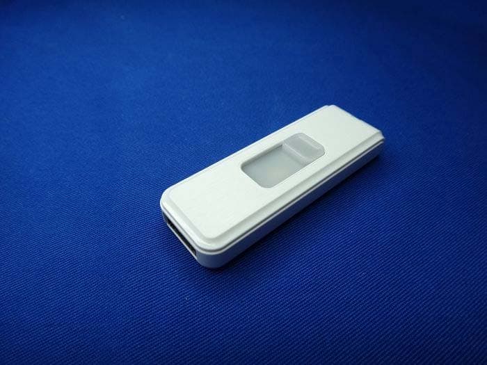
2AASRIREEMOV1
Oct 24, 2013iReemo
Equipment Class
DSS - Part 15 Spread Spectrum Transmitter