2AB7XCHC2XNAA00Chipper 2X
BBPOS Limited
Click to zoom
Application Details
- Equipment Class
- DXX - Part 15 Low Power Communication Device Transmitter
- Date of Grant
- Jul 12, 2015
- Application Purpose
- Original Equipment
- Date of Application
- Jul 11, 2015
- Equipment Note
- Chipper 2X
- Frequency Range
- 13.56000000 - 13.56000000
- Company
- BBPOS Limited
- Country
- Hong Kong
Documents & Files
Document Text
Text extracted from the exhibit documents filed with the FCC. Open a document above to read the original.
Users Manual
In the box • PayAnywhere credit card reader • USB power cable • PayAnywhere lanyard Getting started 1. Apply for a PayAnywhere account. 2. Download the free app. 3. Start accepting credit cards upon account approval. Instructions 1. Plug the PayAnywhere credit card reader into the audio headset port of your mobile device. 2. SET DEVICE VOLUME TO MAXIMUM LEVEL. To power the card reader, you must maximize the volume on your phone. If your phone is not on maximum volume, the encrypted card reader will not work. 3. Launch the PayAnywhere app on your device. 4. Follow the on-screen instructions to begin processing transactions. © 2015 PayAnywhere, LLC. All rights reserved. PayAnywhere (“PA”) is a registered ISO of Wells Fargo Bank, N.A., Walnut Creek, CA. American Express may require separate approval. PA is currently available only in the United States. Requires download of free PA app, approved merchant account, acceptance of terms and conditions, compatible device, and wireless service. Visit PayAnywhere.com/faq for a list of compatible devices and promotional details. Funds usually deposited into your account within 1 business day. Apple, the Apple logo, iPhone and iPad are trademarks of Apple Inc., registered in the U.S. and other countries. Apple Pay and Touch ID are trademarks of Apple Inc. Other designated trademarks and brands are the property of their respective owners. Designed in the USA. Manufactured in China. Power instructions Operating (green light flashing) Low battery (red light flashing) Charging (red light on) Fully charged (green light on) Limited warranty Your PayAnywhere card reader has a 12-month limited warranty. By using the reader on your mobile device, you reaffirm your acceptance of PayAnywhere’s terms, conditions, and disclaimers. FCC Declaration of Conformance This device complies with Part 15 of the FCC Rules. Welcome to PayAnywhere. payanywhere.com/faq Customer Service at 877.387.5640 [email protected] Magnetic stripe transactions Make sure the magnetic stripe is turned towards the large end of the card reader, so that the magnetic stripe and indicator lights are facing towards you. EMV transactions Make sure the electronic chip is turned towards the large end of the card reader and inserted downwards, so that the electronic chip and indicator lights are facing towards you. Contactless NFC transactions Hold an NFC-enabled device or credit card so that it touches the large end of the PayAnywhere card reader. Holding a device too far may result in a failed connection. Swiping tips Maximize your device volume when you launch the app and insert the card reader. Ensure that speakerphone is turned off. If your device has a case or protective sleeve, make sure it is not preventing the card reader from being fully plugged in. EMV capability coming soon. FCC Caution Statements: This device complies with Part 15 of the FCC Rules. Operation is subject to the following two conditions: (1) This device may not cause harmful interference, and (2) this device must accept any interference received, including interference that may cause undesired operation. NOTE: This equipment has been tested and found to comply with the limits for a Class B digital device, pursuant to Part 15 of the FCC Rules. These limits are designed to provide reasonable protection against harmful interference in a residential installation. This equipment generates, uses and can radiate radio frequency energy and, if not installed and used in accordance with the instructions, may cause harmful interference to radio communications. However, there is no guarantee that interference will not occur in a particular installation. If this equipment does cause harmful interference to radio or television reception, which can be determined by turning the equipment off and on, the user is encouraged to try to correct the interference by one of the following measures: - Reorient or relocate the receiving antenna. - Increase the separation between the equipment and receiver. - Connect the equipment into an outlet on a circuit different from that to which the receiver is connected. - Consult the dealer or an experienced radio/TV technician for help. Caution: Any changes or modifications not expressly approved by the party responsible for compliance could void the user's authority to operate this equipment. This transmitter must not be co-located or operating in conjunction with any other antenna or transmitter.
Cover Letter(s)
SCS-F18: Project and Product Certification Representative Authorization Letter Page 1 of 2 Rev 5.0 775 Montague Expressway Milpitas, CA 95035 Tel: 408-526-1188 Fax: 408-526-1088 Email: [email protected] Project and Product Certification Representative Authorization Letter Reason for Amendment (current / obsolete) Revision History Approved Date From To Initial Release (obsolete) 1.0 1.0 Nov-14-2006 Revised wording (obsolete) 1.0 2.0 Sept–25-2007 Updated company template (obsolete) 2.0 3.0 Jan-31-2012 Updated letter information (obsolete) 3.0 4.0 May-23-2014 Added FCC ID field (current) 4.0 5.0 Sept 16 2014 SCS-F18: Project and Product Certification Representative Authorization Letter Page 2 of 2 Rev 5.0 BBPOS Limited Jun. 23, 2015 To: SIEMIC, INC. 775 Montague Expressway, Milpitas, CA 95035 USA Dear Sir/Madam, Re: Product Certification Representative Authorization Letter We, ___BBPOS Limited. ___hereby authorize SIEMIC, Inc. to act as a Certification Body for certifying for the following project(s): (Product description: Chipper 2X , model name: CHC2X) FCC ID: 2AB7XCHC2XNAA00 Sincerely, Client’s signature Client’s name / title Stacey Zhang/ Manager Contact information / address RM812, 8/F., Grand City Plaza, No. 1 Sai Lau Kok Road, Tsuen Wan, N.T. Hong Kong
Cover Letter(s)
SCS-F19: Confidentiality Request Letter Page 1 of 2 Rev 4.0 775 Montague Expressway Milpitas, CA 95035 Tel: 408-526-1188 Fax: 408-526-1088 Email: [email protected] Confidentiality Request Letter Reason for Amendment (current / obsolete) Revision History Approved Date From To Initial Release (obsolete) 1.0 1.0 Nov-14-2006 Adding CFR 2.459 (obsolete) 1.0 2.0 August – 11 - 2008 Updated company template & Added text box (obsolete) 2.0 3.0 Jan-31-2012 Added IC confidentiality letter form (current) 3.0 4.0 March-26-2015 SCS-F19: Confidentiality Request Letter Page 2 of 2 Rev 4.0 BBPOS Limited Date: Jun. 23, 2015 To: Federal Communications Commission Authorization and Evaluation Division 7435 Oakland Mills Road Columbia, MD Subject: Permanent Confidentiality Request for FCC ID: 2AB7XCHC2XNAA00 We hereby request confidential treatment of information accompanying this application as outlined below: - Block Diagram - Schematics - Operational Description The above materials contain trade secrets and proprietary information not customarily released to the public. The public disclosure of these materials may be harmful to the applicant and provide unjustified benefits to its competitors. The applicant understands that pursuant to Section 0.457 & 0.459 of the Rules, disclosure of this application and all accompanying documentation will not be made before the date of the Grant for this application. Sincerely, Client’s signature Client’s name / title Stacey Zhang/ Manager Contact information / address RM812, 8/F., Grand City Plaza, No. 1 Sai Lau Kok Road, Tsuen Wan, N.T. Hong Kong
ID Label/Location Info
Label information: FCC ID: 2AB7XCHC2XNAA00
Test Report
Report No . : EED32H000619-1 Page 1 of 32 TEST REPORT Product: Chipper 2X Trade mark : Chipper 2X Model/Type reference : CHC2X Serial Number : N/A FCC ID : 2AB7XCHC2XNAA00 Ratings: 3.7V,300mAH Report Number : EED32H000619-1 Date: Jun. 11, 2015 Regulations: See below Prepared for BBPOS Limited RM812, 8/F., Grand City Plaza, No. 1 Sai Lau Kok Road, Tsuen Wan, N.T., Hong Kong Prepared by Centre Testing International (Shenzhen) Corporation Building C, Scientific Innovation Park, Tiegang Reservior, Xixiang, Baoan District, Shenzhen, China TEL: +86-755-3368 3668 FAX: +86-755-3368 3385 Tested by: Reviewed by: Approved by: Date: Jun. 11, 2015 Sheek Luo Lab supervisor Check No.: 2135110226 Standards Results 47 CFR FCC Part 15 Subpart C 15.225:2014 PASS Report No. : EED32H000619-1 Page 2 of 32 TABLE OF CONTENTS 1. GENERAL INFORMATION ......................................................................................... 4 2. TEST SUMMARY ........................................................................................................ 4 4. PRODUCT INFORMATION ......................................................................................... 5 5. TEST EQUIPMENT LIST ............................................................................................. 5 6. SUPPORT EQUIPMENT LIST .................................................................................... 6 7. AC CONDUCTED EMISSIONS ................................................................................... 7 7.1 LIMITS ....................................................................................................... 7 7.2 BLOCK DIAGRAM OF TEST SETUP ....................................................... 7 7.3 TEST PROCEDURE .................................................................................. 7 7.4 TEST RESULT ........................................................................................... 8 8. TRANSMITTER FUNDAMENTAL FIELD STRENGTH ............................................. 10 8.1 LIMITS ..................................................................................................... 10 8.2 BLOCK DIAGRAM OF TEST SETUP ..................................................... 10 8.3 TEST PROCEDURE ................................................................................ 10 8.4 TEST RESULT ......................................................................................... 10 9. TRANSMITTER RADIATED SPURIOUS EMISSIONS ............................................. 12 9.1 LIMITS .......................................................................................................... 12 9.2 BLOCK DIAGRAM OF TEST SETUP .......................................................... 12 9.3 TEST PROCEDURE ..................................................................................... 13 9.4TEST RESULT ............................................................................................... 14 10 TRANSMITTER BAND EDGE RADIATED EMISSIONS ......................................... 18 10.1 LIMITS ........................................................................................................ 18 10.2 BLOCK DIAGRAM OF TEST SETUP ........................................................ 18 10.3 TEST PROCEDURE ................................................................................... 18 10.4 TEST RESULT ............................................................................................ 19 11. TRANSMITTER 20 DB BANDWIDTH ..................................................................... 21 11.1 LIMITS ....................................................................................................... 21 11.2 BLOCK DIAGRAM OF TEST SETUP ........................................................ 21 11.3 TEST PROCEDURE ................................................................................... 21 11.4 TEST RESULT ............................................................................................ 21 12. TRANSMITTER FREQUENCY STABILITY ............................................................ 22 12.1 LIMITS ........................................................................................................ 22 12.2 BLOCK DIAGRAM OF TEST SETUP ........................................................ 22 Report No. : EED32H000619-1 Page 3 of 32 12.3 TEST PROCEDURE ................................................................................... 22 12.4 TEST RESULT ............................................................................................ 22 APPENDIX 1 PHOTOGRAPHS OF TEST SETUP ....................................................... 24 APPENDIX 2 PHOTOGRAPHS OF EUT ...................................................................... 26 (Note: N/A means not applicable) Report No. : EED32H000619-1 Page 4 of 32 1. GENERAL INFORMATION The above equipment was tested by Centre Testing International (Shenzhen) Corporation for compliance with the requirements set forth in the FCC Rules and the measurement procedure according to ANSI C63.10:2013. 2. TEST SUMMARY The complete list of measurements is given below: No. Test Item Rule Result 1 AC Conducted Emissions Part 15.207 PASS 2 Transmitter Fundamental Field Strength Part 15.225(a)(b)(c)(d) PASS 3 Transmitter Radiated Spurious Emissions Part 15.209(a), 15.225(d) PASS 4 Transmitter Band Edge Radiated Emissions Part 15.209(a), 15.225(c)(d) PASS 5 Transmitter 20 dB Bandwidth Part 2.1049 PASS 6 Transmitter Frequency Stability (Temperature & Voltage Variation) Part 15.225(e) PASS 7 Antenna Requirements * Part 15.203 PASS *: According to Section 15.203, an intentional radiator shall be designed to ensure that no antenna other than that furnished by the responsible party shall be used with the device. The EUT has a PCB antenna, this is permanently attached antenna and meets the requirements of this section. Applicant: BBPOS Limited RM812, 8/F., Grand City Plaza, No. 1 Sai Lau …
Text truncated - open the document above for the full version.
Contact Information
Applicant
Adrian Kwan
Test Firm
Centre Testing International Group Co., LtdRita Xiao
Technical Specifications
| # | Rule Parts | Frequency Range | Power Output |
|---|---|---|---|
| 1 | 15C | 13.56 MHz - 13.56 MHz | - |
Other Applications from BBPOS Limited
2AB7X-WSP7V1
Sep 22, 2024WisePOS Pro, 7MD
Equipment Class
DSS - Part 15 Spread Spectrum Transmitter
2AB7X-CHB2F
Nov 27, 2021Chipper 2X BT
Equipment Class
DXX - Part 15 Low Power Communication Device Transmitter
2AB7X-CHB2D
Jul 10, 2021Toast Direct Attached
Equipment Class
DXX - Part 15 Low Power Communication Device Transmitter
2AB7X-CHB28
Jul 07, 2021Chipper 2X BT
Equipment Class
DTS - Digital Transmission System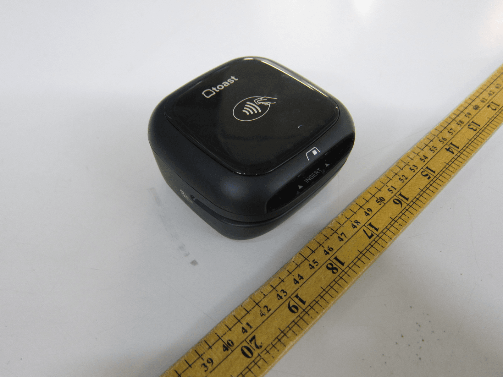
2AB7X-CHB2C
Jun 26, 2021Toast Chipper 2X BT
Equipment Class
DXX - Part 15 Low Power Communication Device Transmitter