2AB8ZND1802.11 a/b/g/n, BLE and BT Module
Intel Corporation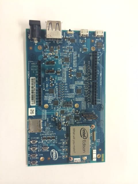
Click to zoom
Application Details
- Equipment Class
- DTS - Digital Transmission System
- Date of Grant
- Aug 24, 2014
- Application Purpose
- Original Equipment
- Date of Application
- Aug 24, 2014
- Equipment Note
- 802.11 a/b/g/n, BLE and BT Module
- Frequency Range
- 2412.00000000 - 2462.00000000
- Company
- Intel Corporation
- Country
- United States
Documents & Files
Document Text
Text extracted from the exhibit documents filed with the FCC. Open a document above to read the original.
Users Manual
Document Number: EQSG-ww29 Intel® Edison Quick Start Guide September 2014 Revision ww29 Intel Confidential Intel® Edison Quick Start Guide September 2014 2 Intel Confidential Document Number: EQSG-ww29 Notice: This document contains information on products in the design phase of development. The information here is subject to change without notice. Do not finalize a design with this information. INFORMATION IN THIS DOCUMENT IS PROVIDED IN CONNECTION WITH INTEL PRODUCTS. NO LICENSE, EXPRESS OR IMPLIED, BY ESTOPPEL OR OTHERWISE, TO ANY INTELLECTUAL PROPERTY RIGHTS IS GRANTED BY THIS DOCUMENT. EXCEPT AS PROVIDED IN INTEL’S TERMS AND CONDITIONS OF SALE FOR SUCH PRODUCTS, INTEL ASSUMES NO LIABILITY WHATSOEVER AND INTEL DISCLAIMS ANY EXPRESS OR IMPLIED WARRANTY, RELATING TO SALE AND/OR USE OF INTEL PRODUCTS INCLUDING LIABILITY OR WARRANTIES RELATING TO FITNESS FOR A PARTICULAR PURPOSE, MERCHANTABILITY, OR INFRINGEMENT OF ANY PATENT, COPYRIGHT OR OTHER INTELLECTUAL PROPERTY RIGHT. A “Mission Critical Application” is any application in which failure of the Intel Product could result, directly or indirectly, in personal injury or death. SHOULD YOU PURCHASE OR USE INTEL’S PRODUCTS FOR ANY SUCH MISSION CRITICAL APPLICATION, YOU SHALL INDEMNIFY AND HOLD INTEL AND ITS SUBSIDIARIES, SUBCONTRACTORS AND AFFILIATES, AND THE DIRECTORS, OFFICERS, AND EMPLOYEES OF EACH, HARMLESS AGAINST ALL CLAIMS COSTS, DAMAGES, AND EXPENSES AND REASONABLE ATTORNEYS' FEES ARISING OUT OF, DIRECTLY OR INDIRECTLY, ANY CLAIM OF PRODUCT LIABILITY, PERSONAL INJURY, OR DEATH ARISING IN ANY WAY OUT OF SUCH MISSION CRITICAL APPLICATION, WHETHER OR NOT INTEL OR ITS SUBCONTRACTOR WAS NEGLIGENT IN THE DESIGN, MANUFACTURE, OR WARNING OF THE INTEL PRODUCT OR ANY OF ITS PARTS. Intel may make changes to specifications and product descriptions at any time, without notice. Designers must not rely on the absence or characteristics of any features or instructions marked “reserved” or “undefined.” Intel reserves these for future definition and shall have no responsibility whatsoever for conflicts or incompatibilities arising from future changes to them. The information here is subject to change without notice. Do not finalize a design with this information. Intel software products are copyrighted by and shall remain the property of Intel Corporation. Use, duplication, or disclosure is subject to restrictions stated in Intel’s Software License Agreement, or in the case of software delivered to the government, in accordance with the software license agreement as defined in FAR 52.227-7013. The products described in this document may contain design defects or errors known as errata which may cause the product to deviate from published specifications. Current characterized errata are available on request. The code names presented in this document are only for use by Intel to identify products, technologies, or services in development that have not been made commercially available to the public, i.e., announced, launched, or shipped. They are not "commercial" names for products or services and are not intended to function as trademarks. Contact your local Intel sales office or your distributor to obtain the latest specifications and before placing your product order. Copies of documents which have an order number and are referenced in this document, or other Intel literature may be obtained by calling 1-800-548-4725 or by visiting Intel’s website at http://www.intel.com/design/literature.htm. Intel processor numbers are not a measure of performance. Processor numbers differentiate features within each processor family, not across different processor families. See http://www.intel.com/products/processor_number for details. Intel, the Intel logo, and Edison are trademarks of Intel Corporation in the US and other countries. * Other brands and names may be claimed as the property of others. Copyright © 2014 Intel Corporation. All rights reserved. Intel® Edison September 2014 Quick Start Guide Document Number: EQSG-ww29 Intel Confidential 3 Contents 1 Introduction ......................................................................................................................................................... 6 1.1 References ............................................................................................................................................. 6 1.2 Terminology ............................................................................................................................................ 6 1.3 Typographic conventions ....................................................................................................................... 6 2 Overview .............................................................................................................................................................. 7 2.1 Before you begin .................................................................................................................................... 8 3 Windows Configuration ..................................................................................................................................... 9 3.1 Connect to Edison through USB/UART serial ........................................................................................ 9 Downloads ........................................................................................................................ 9 3.1.1 Initial setup ........................................................................................................................ 9 3.1.2 Connecting to Edison ....................................................................................................... 9 3.1.3 3.2 Connect through RNDIS ...................................................................................................................... 10 Downloads ........................................................................................................…
Text truncated - open the document above for the full version.
Cover Letter(s)
Intel Corporation 2200 Mission College Blvd Santa Clara, CA 95054 Federal Communications Commission Equipment Authorization branch 7435 Oakland Mills Road Columbia, MD 21046 To whom it may concern: I, the undersigned, hereby authorize UL Verification Services Inc. to act on our behalf in all manners relating to application for equipment authorization, including signing of all documents relating to these matters. Any and all acts carried out by UL Verification Services Inc. on our behalf shall have the same effect as acts of our own. I, the undersigned, hereby certify that we are not subject to a denial of federal benefits, that includes FCC benefits, pursuant to Section 5301 of the Anti-Drug Abuse Act of 1988, 21 U.S.C. 853(a). In authorizing UL Verification Services Inc. as our representative, we still recognize that we are responsible to: a) comply with the relevant provisions of the certification program; b) make all necessary arrangements for the conduct of the evaluation, including provision for examining documentation and access to all areas, records (including internal audit reports) and personnel for the purposes of evaluation (e.g. testing, inspection, assessment, surveillance, reassessment) and resolution of complaints; c) make claims regarding certification only in respect of the scope for which certification has been granted; d) do not use our product certification in such a manner as to bring the Certification Division into disrepute and not make any statement regarding our product certification which the Certification Division may consider misleading or unauthorized; e) upon suspension or cancellation of certification, discontinue use of all advertising matter that contains any reference thereto and return any certification documents as required by the Certification Division; f) use certification only to indicate the products are certified as being in conformity with specified standards; Intel Corporation 2200 Mission College Blvd Santa Clara, CA 95054 g) endeavor to ensure that no certificate or report nor any part thereof is used in a misleading manner; h) ensure that any reference to our product certification in communication media such as documents, brochures or advertising, complies with the requirements of the Certification Division; i) keep a record of all complaints made known to the us relating to the product’s compliance with requirements of the relevant standard and to make these records available to the when requested; j) take appropriate action with respect to such complaints and any deficiencies found in products or services that affect compliance with the requirements for certification; k) document the actions taken. This authorization is valid until further written notice from the applicant. Sincerely Yours, , 8/12/2014 Masood Abrishamcar Compliance Manager Intel Corporation
Cover Letter(s)
Company: Intel Corporation FCC ID:2AB8ZND1 Request for transmitter modular approval Transmitter Module Characteristics Item Requirements EUT 1 Have its own RF shielding Device is equipped with Metal shielding to cover RF section. Refer to external photos 2 Have buffered modulation/data inputs (if such inputs are provided), All inputs to the modules are buffered through logic or microprocessor inputs. 3 Have it own power supply regulation Internal 1.8V power regulator. Refer to Block diagram 4 Meet the antenna requirements of Section 15.203 Device is equipped with on board chip antenna 5 Be tested in a stand-alone configuration, i.e., the antenna, AC or DC power and data input/output lines must be connected to the module but, the module must not be inside another case during testing Device was tested with test board Arduino and Break out board Refer to setup photos. 6 Be labeled with its own FCC ID number, and if the FCC ID is not visible when the module is installed inside another device, then the outside of the device into which the module is installed must also display a label referring to the enclosed module. FCC ID will be placed on the module shield, refer to artwork drawing 7 The modular transmitter is manufactured so that the user cannot influence the operation of the transmitter that will operate outside of the scope of the regulations. Refer to “User’s Guide” Exhibit 8 Address compliance with the Commission's RF exposure limits in Sections 1.1310 and 2.1093. In addition, spread spectrum transmitters operating under Section 15.247 are required to address RF exposure compliance in accordance with Section 15.247(b)(4). SAR test was performed on the module, two configuration: 1) At 5mm separation, for wearable version and 2) At 17 mm separation non wearable version
Cover Letter(s)
Intel Corporation 2200 Mission College Blvd Santa Clara, CA 95054 Federal Communications Commission 7435 Oakland Mills Road Columbia MD 21046 Subject: Request for Confidentiality FCC ID: 2AB8ZND1 To Whom It May Concern: Pursuant to the provisions of Sections 0.457 and 0.459 of the Commission’s rules (47 CFR §§ 0.457, 0.459), we are requesting the Commission to withhold the following attachments as confidential document from public disclosure indefinitely. Schematic Diagram Block Diagram Theory of Operation Above mentioned document contains detailed system and equipment description are considered as proprietary information in operation of the equipment. The public disclosure of above documents might be harmful to our company and would give competitor an unfair advantage in the market. In additional to above mentioned documents, pursuant to Public Notice DA 04-1705 of the Commission’s policy, in order to comply with the marketing regulations in 47 CFR §2.803 and the importation rules in 47 CFR §2.1204, while ensuring that business sensitive information remains confidential until the actual marketing of newly authorized devices. We are requesting the commission to grant short-term confidentiality request on the following attachments until 180 days. External Photos Internal Photos Test Setup Photos User Manual It is our understanding that all measurement test reports, FCC ID label format and correspondent during certification review process cannot be granted as confidential documents and those information will be available for public review once the grant of equipment authorization is issued. Best Regards , 8/12/2014 Masood Abrishamcar Compliance Manager Intel Corporation
External Photos
Edison with shield & Breakout board Edison with shield & Arduino Board Edison top without shield Edison back with shield Edison back without shield
ID Label/Location Info
FCC and IC location on top shield
Internal Photos
Edison with shield & Breakout board Edison with shield & Arduino Board Edison top without shield Edison back with shield Edison back without shield
RF Exposure Info
FCC Part 1 Subpart I FCC Part 2 Subpart J INDUSTRY CANADA RSS 102 ISSUE 4 RF EXPOSURE REPORT FOR 802.11 a/b/g/n, BLE, and BT module MODEL NUMBER: EDISON FCC ID: 2AB8ZND1 IC: 1000X-ND1 REPORT NUMBER: 14U17976-E28 ISSUE DATE: AUGUST 25, 2014 Prepared for INTEL CORPORATON 2200 MISSION COLLEGE BOULEVARD SANTA CLARA, CA 95052, U.S.A Prepared by UL VERIFICATION SERVICES INC. 47173 BENICIA STREET FREMONT, CA 94538, U.S.A. TEL: (510) 771-1000 FAX: (510) 661-0888 REPORT NO: 14U17976-E28 DATE: AUGUST 25, 2014 FCC ID: 2AB8ZND1 IC ID: 1000X-ND1 Page 2 of 12 UL VERIFICATION SERVICES INC. FORM NO: CCSUP4701I 47173 BENICIA STREET, FREMONT, CA 94538, USA TEL: (510) 771-1000 FAX: (510) 661-0888 This report shall not be reproduced except in full, without the written approval of . UL Verification Services Inc. Revision History Rev. Issue Date Revisions Revised By -- 08/25/14 Initial Issue C.S.OOI REPORT NO: 14U17976-E28 DATE: AUGUST 25, 2014 FCC ID: 2AB8ZND1 IC ID: 1000X-ND1 Page 3 of 12 UL VERIFICATION SERVICES INC. FORM NO: CCSUP4701I 47173 BENICIA STREET, FREMONT, CA 94538, USA TEL: (510) 771-1000 FAX: (510) 661-0888 This report shall not be reproduced except in full, without the written approval of . UL Verification Services Inc. TABLE OF CONTENTS 1. ATTESTATION OF TEST RESULTS ................................................................................. 4 2. TEST METHODOLOGY ..................................................................................................... 5 3. REFERENCES ................................................................................................................... 5 4. FACILITIES AND ACCREDITATION ................................................................................. 5 5. MAXIMUM PERMISSIBLE RF EXPOSURE ....................................................................... 6 5.1. FCC RULES ................................................................................................................ 6 5.2. IC RULES .................................................................................................................... 7 5.3. EQUATIONS ................................................................................................................ 8 5.4. LIMITS AND IC EXEMPTION .....................................................................................10 6. RF EXPOSURE RESULTS ................................................................................................11 REPORT NO: 14U17976-E28 DATE: AUGUST 25, 2014 FCC ID: 2AB8ZND1 IC ID: 1000X-ND1 Page 4 of 12 UL VERIFICATION SERVICES INC. FORM NO: CCSUP4701I 47173 BENICIA STREET, FREMONT, CA 94538, USA TEL: (510) 771-1000 FAX: (510) 661-0888 This report shall not be reproduced except in full, without the written approval of . UL Verification Services Inc. 1. ATTESTATION OF TEST RESULTS COMPANY NAME: INTEL CORPORATION 2200 MISSION COLLEGE BOULEVARD SANTA CLARA, CA 95052, U.S.A EUT DESCRIPTION: 802.11 a/b/g/n, BLE, and BT module MODEL: EDISON SERIAL NUMBER: SKU10 ( For Conducted ) and SKU9 ( For Radiated ) DATE TESTED: JUNE 26, 2014 – AUGUST 1, 2014 APPLICABLE STANDARDS STANDARD TEST RESULTS FCC PART 1 SUBPART I & PART 2 SUBPART J Pass INDUSTRY CANADA RSS 102 ISSUE 4 Pass UL Verification Services Inc. calculated the RF Exposure of the above equipment in accordance with the requirements set forth in the above standards, using test results reported in the test report documents referenced below and/or documentation furnished by the applicant. All indications of Pass/Fail in this report are opinions expressed by UL Verification Services Inc. based on interpretations of these calculations. The results show that the equipment is capable of demonstrating compliance with the requirements as documented in this report. Note: The results documented in this report apply only to the tested sample, under the conditions and modes of operation as described herein. This document may not be altered or revised in any way unless done so by UL Verification Services Inc. and all revisions are duly noted in the revisions section. Any alteration of this document not carried out by UL Verification Services Inc. will constitute fraud and shall nullify the document. This report must not be used by the client to claim product certification, approval, or endorsement by NVLAP, NIST, any agency of the Federal Government, or any agency of any government. Approved & Released For UL Verification Services Inc. By: Calculated By: CHOON SIAN OOI THANH PHAM PROJECT LEAD EMC ENGINEER UL Verification Services Inc. UL Verification Services Inc. REPORT NO: 14U17976-E28 DATE: AUGUST 25, 2014 FCC ID: 2AB8ZND1 IC ID: 1000X-ND1 Page 5 of 12 UL VERIFICATION SERVICES INC. FORM NO: CCSUP4701I 47173 BENICIA STREET, FREMONT, CA 94538, USA TEL: (510) 771-1000 FAX: (510) 661-0888 This report shall not be reproduced except in full, without the written approval of . UL Verification Services Inc. 2. TEST METHODOLOGY All calculations were made in accordance with FCC OET Bulletin 65 Edition 97-01 and IC Safety Code 6. 3. REFERENCES Document 14U17976-E1 for operation in the 2.4 GHz band and UL Verification Services Inc. Document 14U17976-E3 for operation in the 5 GHz bands. Output power, Duty cycle and Antenna gain data is excerpted from the applicable test reports. 4. FACILITIES AND ACCREDITATION The test sites and measurement facilities used to collect data are located at 47173 Benicia Street, Fremont, California, USA. UL Verification Services Inc. is accredited by NVLAP, Laboratory Code 200065-0. The full scope of accreditation can be viewed at http://ts.nist.gov/standards/scopes/2000650.htm. REPORT NO: 14U17976-E28 DATE: AUGUST 25, 2014 FCC ID: 2AB8ZND1 IC ID: 1000X-ND1 Page 6 of 12 UL VERIFICATION SERVICES INC. FORM NO: CCSUP4701I 47173 BENICIA STREET, FREMONT, CA 94538, USA TEL: (510) 771-1000 FAX: (510) 661-0888 This report shall not be reproduced except in full, without the written approval of . UL Verification Services …
Text truncated - open the document above for the full version.
RF Exposure Info
Plot No. 1 Test Laboratory: UL Verification Services Inc., SAR Lab 3 Date: 7/31/2014 20140731_SystemPerformanceCheck-D2450V2 SN 899 Frequency: 2450 MHz; Duty Cycle: 1:1; Room Ambient Temperature: 24.0°C; Liquid Temperature: 23.0°C Medium parameters used: f = 2450 MHz; σ = 1.964 S/m; ε r = 51.797; ρ = 1000 kg/m 3 DASY5 Configuration: - Area Scan Setting: Find Secondary Maximum Within: 2.0 dB and with a peak SAR value greater than 0.0012W/kg - Averaged Fast SAR: Polynomial fit - Electronics: DAE4 Sn1257; Calibrated: 7/16/2014 - Probe: EX3DV4 - SN3773; ConvF(6.67, 6.67, 6.67); Calibrated: 4/22/2014; - Sensor-Surface: 2.5mm (Mechanical Surface Detection) - Phantom: ELI v5.0 (A); Type: QDOVA001BB; Serial: 1213 Body/Pin=100 mW/Area Scan (71x71x1): Interpolated grid: dx=1.200 mm, dy=1.200 mm Reference Value = 49.97 V/m; Power Drift = 0.08 dB Fast SAR: SAR(1 g) = 5.33 W/kg; SAR(10 g) = 2.26 W/kg Maximum value of SAR (interpolated) = 7.85 W/kg Body/Pin=100 mW/Zoom Scan (7x7x7)/Cube 0: Measurement grid: dx=5mm, dy=5mm, dz=5mm Reference Value = 49.97 V/m; Power Drift = 0.08 dB Peak SAR (extrapolated) = 11.1 W/kg SAR(1 g) = 5.4 W/kg; SAR(10 g) = 2.51 W/kg Maximum value of SAR (measured) = 7.67 W/kg 0 dB = 7.67 W/kg = 8.85 dBW/kg Plot No. 2 Test Laboratory: UL Verification Services Inc., SAR Lab 3 Date: 7/31/2014 20140731_SystemPerformanceCheck-D2450V2 SN 899 Frequency: 2450 MHz; Duty Cycle: 1:1 Body/Pin=100 mW/Z Scan (1x1x21): Measurement grid: dx=20mm, dy=20mm, dz=5mm Maximum value of SAR (measured) = 4.80 W/kg Plot No. 3 Test Laboratory: UL Verification Services Inc., SAR Lab 3 Date: 7/31/2014 20140731_SystemPerformanceCheck-D5GHzV2 SN 1138 Frequency: 5600 MHz; Duty Cycle: 1:1; Room Ambient Temperature: 24.0°C; Liquid Temperature: 23.0°C Medium parameters used: f = 5600 MHz; σ = 5.89 S/m; ε r = 46.371; ρ = 1000 kg/m 3 DASY5 Configuration: - Area Scan Setting: Find Secondary Maximum Within: 2.0 dB and with a peak SAR value greater than 0.0012W/kg - Averaged Fast SAR: Polynomial fit - Electronics: DAE4 Sn1257; Calibrated: 7/16/2014 - Probe: EX3DV4 - SN3773; ConvF(3.75, 3.75, 3.75); Calibrated: 4/22/2014; - Sensor-Surface: 1.4mm (Mechanical Surface Detection) - Phantom: ELI-B v5.0; Type: QDOVA001BB; Serial: 1215 Body/5.6 GHz, Pin=100mW/Area Scan (61x61x1): Interpolated grid: dx=1.000 mm, dy=1.000 mm Reference Value = 51.14 V/m; Power Drift = 0.15 dB Fast SAR: SAR(1 g) = 7.71 W/kg; SAR(10 g) = 2.08 W/kg Maximum value of SAR (interpolated) = 21.1 W/kg Body/5.6 GHz, Pin=100mW/Zoom Scan (8x8x7)/Cube 0: Measurement grid: dx=4mm, dy=4mm, dz=1.4mm Reference Value = 51.14 V/m; Power Drift = 0.15 dB Peak SAR (extrapolated) = 38.1 W/kg SAR(1 g) = 8.24 W/kg; SAR(10 g) = 2.29 W/kg Maximum value of SAR (measured) = 20.3 W/kg 0 dB = 20.3 W/kg = 13.07 dBW/kg Plot No. 4 Test Laboratory: UL Verification Services Inc., SAR Lab 3 Date: 7/31/2014 20140731_SystemPerformanceCheck-D5GHzV2 SN 1138 Frequency: 5600 MHz; Duty Cycle: 1:1 Body/5.6 GHz, Pin=100mW/Z Scan (1x1x21): Measurement grid: dx=20mm, dy=20mm, dz=5mm Maximum value of SAR (measured) = 14.1 W/kg Plot No. 5 Test Laboratory: UL Verification Services Inc., SAR Lab 5 Date: 8/23/2014 20140823_SystemPerformanceCheck-D2450V2 SN 899 Frequency: 2450 MHz; Duty Cycle: 1:1; Room Ambient Temperature: 24.0°C; Liquid Temperature: 23.0°C Medium parameters used: f = 2450 MHz; σ = 2.032 S/m; ε r = 51.308; ρ = 1000 kg/m 3 DASY5 Configuration: - Area Scan Setting: Find Secondary Maximum Within: 2.0 dB and with a peak SAR value greater than 0.0012W/kg - Averaged Fast SAR: Polynomial fit - Electronics: DAE4 Sn1439; Calibrated: 5/14/2014 - Probe: EX3DV4 - SN3991; ConvF(7.23, 7.23, 7.23); Calibrated: 5/16/2014; - Sensor-Surface: 2.5mm (Mechanical Surface Detection) - Phantom: ELI v5.0 (A); Type: QDOVA001BB; Serial: 1213 Body/Pin=100 mW/Area Scan (71x71x1): Interpolated grid: dx=1.200 mm, dy=1.200 mm Reference Value = 56.48 V/m; Power Drift = 0.02 dB Fast SAR: SAR(1 g) = 4.7 W/kg; SAR(10 g) = 2.04 W/kg Maximum value of SAR (interpolated) = 6.89 W/kg Body/Pin=100 mW/Zoom Scan (7x7x7)/Cube 0: Measurement grid: dx=5mm, dy=5mm, dz=5mm Reference Value = 56.48 V/m; Power Drift = 0.02 dB Peak SAR (extrapolated) = 9.89 W/kg SAR(1 g) = 4.7 W/kg; SAR(10 g) = 2.16 W/kg Maximum value of SAR (measured) = 6.71 W/kg 0 dB = 6.71 W/kg = 8.27 dBW/kg Plot No. 6 Test Laboratory: UL Verification Services Inc., SAR Lab 5 Date: 8/23/2014 20140823_SystemPerformanceCheck-D2450V2 SN 899 Frequency: 2450 MHz; Duty Cycle: 1:1 Body/Pin=100 mW/Z Scan (1x1x21): Measurement grid: dx=20mm, dy=20mm, dz=5mm Maximum value of SAR (measured) = 6.42 W/kg Plot No. 1 Test Laboratory: UL Verification Services Inc., SAR Lab 3 Date: 7/23/2014 Wi-Fi 2.4GHz Frequency: 2437 MHz; Duty Cycle: 1:1; Room Ambient Temperature: 24.0°C; Liquid Temperature: 23.0°C Medium parameters used (interpolated): f = 2437 MHz; σ = 1.962 S/m; ε r = 50.259; ρ = 1000 kg/m 3 DASY5 Configuration: - Area Scan Setting: Find Secondary Maximum Within: 2.0 dB and with a peak SAR value greater than 0.0012W/kg - Electronics: DAE4 Sn1257; Calibrated: 7/16/2014 - Probe: EX3DV4 - SN3773; ConvF(6.67, 6.67, 6.67); Calibrated: 4/22/2014; - Sensor-Surface: 2.5mm (Mechanical Surface Detection) - Phantom: ELI v5.0 (A); Type: QDOVA001BB; Serial: 1213 Rear 7_22_2014/802.11n ht20_ch 6_Pwr Sett. 54/Area Scan (9x9x1): Measurement grid: dx=12mm, dy=12mm Info: Interpolated medium parameters used for SAR evaluation. Maximum value of SAR (measured) = 0.491 W/kg Rear 7_22_2014/802.11n ht20_ch 6_Pwr Sett. 54/Zoom Scan (7x7x7)/Cube 0: Measurement grid: dx=5mm, dy=5mm, dz=5mm Reference Value = 15.92 V/m; Power Drift = -0.02 dB Peak SAR (extrapolated) = 0.836 W/kg SAR(1 g) = 0.400 W/kg; SAR(10 g) = 0.188 W/kg Info: Interpolated medium parameters used for SAR evaluation. Maximum value of SAR (measured) = 0.548 W/kg 0 dB = 0.548 W/kg = -2.61 dBW/kg Plot No. 2 Test Laboratory: UL Verification Services Inc., SAR Lab 3 Date: 7/24/2014 Wi-Fi 5GHz -2014-07-22 Frequency: 5200 MHz; Duty Cycle: …
Text truncated - open the document above for the full version.
RF Exposure Info
Plot No. 1 Test Laboratory: UL Verification Services Inc., SAR Lab 3 Date: 7/28/2014 20140728SystemPerformanceCheck-D2450V2 SN 899 Frequency: 2450 MHz; Duty Cycle: 1:1; Room Ambient Temperature: 24.0°C; Liquid Temperature: 23.0°C Medium parameters used: f = 2450 MHz; σ = 2.024 S/m; ε r = 50.525; ρ = 1000 kg/m 3 DASY5 Configuration: - Area Scan Setting: Find Secondary Maximum Within: 2.0 dB and with a peak SAR value greater than 0.0012W/kg - Averaged Fast SAR: Polynomial fit - Electronics: DAE4 Sn1257; Calibrated: 7/16/2014 - Probe: EX3DV4 - SN3773; ConvF(6.67, 6.67, 6.67); Calibrated: 4/22/2014; - Sensor-Surface: 2.5mm (Mechanical Surface Detection) - Phantom: ELI v5.0 (A); Type: QDOVA001BB; Serial: 1213 Body/Pin=100 mW/Area Scan (71x71x1): Interpolated grid: dx=1.200 mm, dy=1.200 mm Reference Value = 46.43 V/m; Power Drift = 0.11 dB Fast SAR: SAR(1 g) = 5.02 W/kg; SAR(10 g) = 2.14 W/kg Maximum value of SAR (interpolated) = 7.38 W/kg Body/Pin=100 mW/Zoom Scan (7x7x7)/Cube 0: Measurement grid: dx=5mm, dy=5mm, dz=5mm Reference Value = 46.43 V/m; Power Drift = 0.11 dB Peak SAR (extrapolated) = 10.5 W/kg SAR(1 g) = 5.06 W/kg; SAR(10 g) = 2.34 W/kg Maximum value of SAR (measured) = 7.19 W/kg 0 dB = 7.19 W/kg = 8.57 dBW/kg Plot No. 2 Test Laboratory: UL Verification Services Inc., SAR Lab 3 Date: 7/28/2014 20140728SystemPerformanceCheck-D2450V2 SN 899 Frequency: 2450 MHz; Duty Cycle: 1:1 Body/Pin=100 mW/Z Scan (1x1x21): Measurement grid: dx=20mm, dy=20mm, dz=5mm Maximum value of SAR (measured) = 4.29 W/kg Plot No. 3 Test Laboratory: UL Verification Services Inc., SAR Lab 3 Date: 7/31/2014 20140731_SystemPerformanceCheck-D2450V2 SN 899 Frequency: 2450 MHz; Duty Cycle: 1:1; Room Ambient Temperature: 24.0°C; Liquid Temperature: 23.0°C Medium parameters used: f = 2450 MHz; σ = 1.964 S/m; ε r = 51.797; ρ = 1000 kg/m 3 DASY5 Configuration: - Area Scan Setting: Find Secondary Maximum Within: 2.0 dB and with a peak SAR value greater than 0.0012W/kg - Averaged Fast SAR: Polynomial fit - Electronics: DAE4 Sn1257; Calibrated: 7/16/2014 - Probe: EX3DV4 - SN3773; ConvF(6.67, 6.67, 6.67); Calibrated: 4/22/2014; - Sensor-Surface: 2.5mm (Mechanical Surface Detection) - Phantom: ELI v5.0 (A); Type: QDOVA001BB; Serial: 1213 Body/Pin=100 mW/Area Scan (71x71x1): Interpolated grid: dx=1.200 mm, dy=1.200 mm Reference Value = 49.97 V/m; Power Drift = 0.08 dB Fast SAR: SAR(1 g) = 5.33 W/kg; SAR(10 g) = 2.26 W/kg Maximum value of SAR (interpolated) = 7.85 W/kg Body/Pin=100 mW/Zoom Scan (7x7x7)/Cube 0: Measurement grid: dx=5mm, dy=5mm, dz=5mm Reference Value = 49.97 V/m; Power Drift = 0.08 dB Peak SAR (extrapolated) = 11.1 W/kg SAR(1 g) = 5.4 W/kg; SAR(10 g) = 2.51 W/kg Maximum value of SAR (measured) = 7.67 W/kg 0 dB = 7.67 W/kg = 8.85 dBW/kg Plot No. 4 Test Laboratory: UL Verification Services Inc., SAR Lab 3 Date: 7/31/2014 20140731_SystemPerformanceCheck-D2450V2 SN 899 Frequency: 2450 MHz; Duty Cycle: 1:1 Body/Pin=100 mW/Z Scan (1x1x21): Measurement grid: dx=20mm, dy=20mm, dz=5mm Maximum value of SAR (measured) = 4.80 W/kg Plot No. 1 Test Laboratory: UL Verification Services Inc., SAR Lab 3 Date: 7/29/2014 Wi-Fi 2.4GHz_Distance Frequency: 2437 MHz; Duty Cycle: 1:1; Room Ambient Temperature: 24.0°C; Liquid Temperature: 23.0°C Medium parameters used (interpolated): f = 2437 MHz; σ = 2.006 S/m; ε r = 50.583; ρ = 1000 kg/m 3 DASY5 Configuration: - Area Scan Setting: Find Secondary Maximum Within: 2.0 dB and with a peak SAR value greater than 0.0012W/kg - Electronics: DAE4 Sn1257; Calibrated: 7/16/2014 - Probe: EX3DV4 - SN3773; ConvF(6.67, 6.67, 6.67); Calibrated: 4/22/2014; - Sensor-Surface: 2.5mm (Mechanical Surface Detection (Locations From Previous Scan Used)), Sensor-Surface: 2.5mm (Mechanical Surface Detection) - Phantom: ELI v5.0 (A); Type: QDOVA001BB; Serial: 1213 Front/802.11n 17 mm Dist._HT20_ch 6/Area Scan (9x9x1): Measurement grid: dx=12mm, dy=12mm Info: Interpolated medium parameters used for SAR evaluation. Maximum value of SAR (measured) = 0.456 W/kg Front/802.11n 17 mm Dist._HT20_ch 6/Zoom Scan (7x7x7)/Cube 0: Measurement grid: dx=5mm, dy=5mm, dz=5mm Reference Value = 15.03 V/m; Power Drift = 0.03 dB Peak SAR (extrapolated) = 0.656 W/kg SAR(1 g) = 0.369 W/kg; SAR(10 g) = 0.208 W/kg Info: Interpolated medium parameters used for SAR evaluation. Maximum value of SAR (measured) = 0.480 W/kg 0 dB = 0.480 W/kg = -3.19 dBW/kg
RF Exposure Info
NVLAP LAB CODE 200065-0 SAR EVALUATION REPORT FCC 47 CFR § 2.1093 IEEE Std 1528-2013 For 802.11abgn w/BT 4.0 Model: EDISON FCC ID: 2AB8ZND1 Report Number: 14U17814-S1D Issue Date: 8/27/2014 Prepared for INTEL CORPORATION 2200 MISSION COLLEGE BOULEVARD SANTA CLARA, CA 95052, U.S.A Prepared by UL Verification Services Inc. 47173 BENICIA STREET FREMONT, CA 94538, U.S.A. TEL: (510) 771-1000 FAX: (510) 661-0888 Report No.: 14U17814-S1D Issue Date: 8/27/2014 FCC ID: 2AB8ZND1 Page 2 of 26 UL Verification Services Inc. Doc. No.: 1.0 This report shall not be reproduced without the written approval of UL Verification Services Inc. REVISION HISTORY Rev. Issue Date Revisions Revised By -- 8/19/2014 Initial Issue -- A 8/21/2014 Section 4.2 – corrected equipment list Appendix – Added SAR probe Calibration certificate. Dave Weaver B 8/23/2014 Added Bluetooth and simultaneous transmission results Dave Weaver C 8/25/2014 Section 7.2 – Correct…
Text truncated - open the document above for the full version.
Contact Information
Applicant
Masood Abrishamcar
Technical Contact
UL Verification ServicesGrace Rincand
[email protected]510-771-1000
47173 Benicia Street · Fremont · United States
Test Firm
UL Verification Services Inc. (formerly UL CCS)Jay Kogoma
Technical Specifications
| # | Rule Parts | Frequency Range | Power Output |
|---|---|---|---|
| 2 | 15C | 2.41 GHz - 2.46 GHz | 51.00 mW |
Other Applications from Intel Corporation
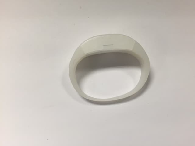
2AB8ZND13
Jan 04, 2016LED Interactive Wristband with LED
Equipment Class
DTS - Digital Transmission System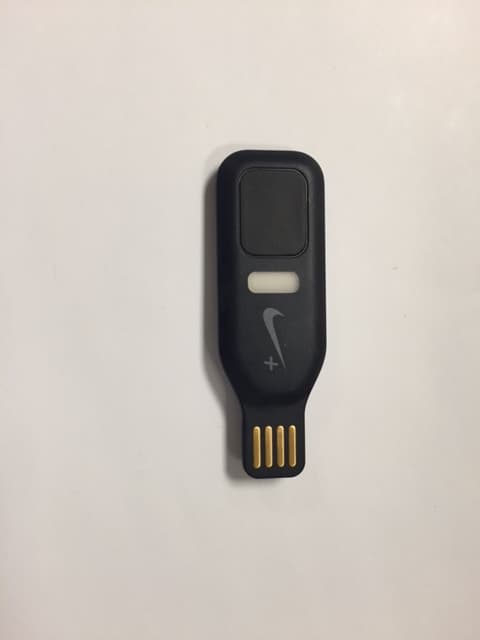
2AB8ZND6
Dec 10, 2015Health Monitoring Device
Equipment Class
DTS - Digital Transmission System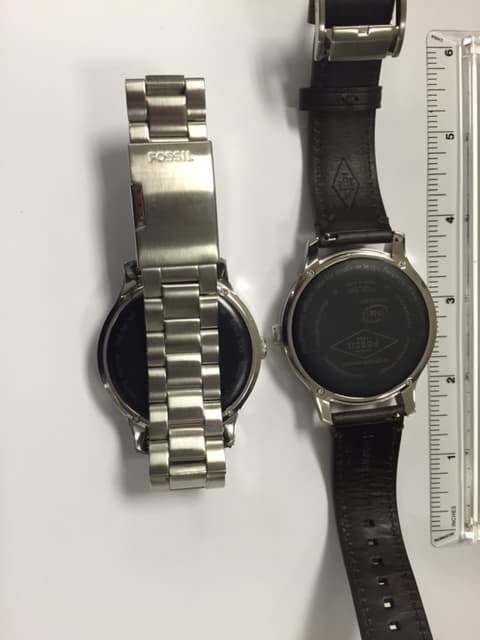
2AB8ZND10
Oct 22, 2015SMART WATCH WITH 802.11B/G/N, BLUETOOTH AND BLE
Equipment Class
DTS - Digital Transmission System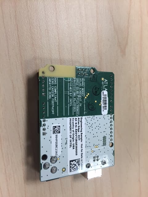
2AB8ZND12
Oct 08, 2015BLE MODULE
Equipment Class
DTS - Digital Transmission System
2AB8ZND7
Sep 17, 2015Wireless Charger
Equipment Class
DCD - Part 15 Low Power Transmitter Below 1705 kHz