2AB8ZND4Wearable Device
Intel Corporation
Click to zoom
Application Details
- Equipment Class
- DTS - Digital Transmission System
- Date of Grant
- Jun 30, 2015
- Application Purpose
- Original Equipment
- Date of Application
- Jun 29, 2015
- Equipment Note
- Wearable Device
- Frequency Range
- 2402.00000000 - 2480.00000000
- Company
- Intel Corporation
- Country
- United States
Documents & Files
Document Text
Text extracted from the exhibit documents filed with the FCC. Open a document above to read the original.
Users Manual
Model: FTW1000 FCC Statement (USA) This equipment has been tested and found to comply with the limits for a Class B digital device, pursuant to Part 15 of the FCC Rules. These limits are designed to provide reasonable protection against harmful interference in a residential installation. This equipment generates, uses, and can radiate radio frequency energy and, if not installed and used in accordance with the instructions, may cause harmful interference to radio communications. However, there is no guarantee that interference will not occur in a particular installation. If this equipment does cause harmful interference to radio or television reception, which can be determined by turning the equipment off and on, the user is encouraged to try to correct the interference by one or more of the following measures: ● Reorient or relocate the receiving antenna. ● Increase the separation between the equipment and receiver. ● Connect the equipment to an outlet on a circuit different from that to which the receiver is connected. ● Consult the dealer or an experienced radio or television technician for help. This device complies with part 15 of the FCC Rules. Operation is subject to the following two conditions: (1) This device may not cause harmful interference, and (2) this device must accept any interference received, including interference that may cause undesired operation. WARNING! Exposure to Radio Frequency Radiation The radiated output power of this device is below the FCC and Industry Canada radio frequency exposure limits. This device must not be co-‐located or operating in conjunction with any other antenna or transmitter. FCC requires the user to be notified that any changes or modifications made to this device that are not expressly approved by manufacture, may void the user’s authority to use the device ICES-‐003 (Canada) This digital apparatus does not exceed the Class B limits for radio noise emissions from digital apparatus set out in the interfer-‐ ence-‐causing equipment standard entitled: “Digital Apparatus,” ICES-‐003 of the Canadian Department of Communications. Cet appareil numérique respecte les limites bruits radioélectriques applicables aux appareils numériques de Classe Bprescrites dans la norme sur le matériel brouilleur: "Appareils Numériques", NMB-‐003 édictee par le Ministre Canadian des Communications. This device complies with Industry Canada license-‐exempt RSS standard(s). Operation is subject to the following two conditions: (1) this device may not cause interference, and (2) this device must accept any interference, including interference that may cause undesired operation of the device. Le présent appareil est conforme aux CNR d’Industrie Canada applicables aux appareils radio exempts de licence. L’exploitation est autorisée aux deux conditions suivantes : (1) l’appareil ne doit pas produire de brouillage, et (2) l’utilisateur de l’appareil doit accepter tout brouillage radioélectrique subi, même si le brouillage est susceptible d’en compromettre le fonctionnement. Europe (CE Declaration of Conformity) This product complies with the Low Voltage Directive 2006/95/EC; EMC Directive 2004/108/EC, EU Directive R&TTE Directive 1999/5/EC, and RoHS Directive 2011/65/EU. Point of contact: (please add your company name), Attn: (Please add your corporate address) "In the EU, this symbol means that this product must not be disposed of with household waste. It is your responsibility to bring it to a designated collection point for the recycling of waste electrical and electronic equipment. For more information, please contact your local waste collection center or your point of purchase of this product."
Users Manual
Intel Corporation 2200 Mission College Blvd Santa Clara, CA 95054 FCC ID: 2AB8ZND4 IC: 1000X-‐ND4 OEM Integration procedure: To insure compliance with FCC and Canada IC, the following steps should be followed for integration of Intel BT BLE module to the host: 1) FCC ID should be visible to the user after integration of module into bracelet. 2) IC number should be visible to the user after integration of module into bracelet. 3) Use in other bracelets may require submission of a C2PC filing for FCC and either reassessment or model addition for Industry Canada. Please work with Intel to determine the appropriate procedures. 4) User documentation with the regulatory statements required by FCC and Canada, as described in the sample manual provided to Intel, must be provided to the end user.
Users Manual
Q FOUNDER Connect Start Touch Screen Mic Micro USB Cable Charging Cu Wall Adaptor Power/ Home Button Support Features Charge For full user’s guide, sizing, tutorials and helpful tips, visit Fossil and Stylized Q logo are trademarks or registered trademarks of Fossil Inc, LLC. All other product or service names are the property of their respective owners. ©Fossil Inc, LLC. All rights reserved. Product ID: Marvin Manual Number: 00000054 www.fossil.com/Q Insert the micro USB cable into connection on bottom of charging cu . Plug into power outlet. Contents Download and install the Android wear app and Fossil Q app from the App Store SM or Google Play store™. Open app on your device and follow the prompts to pair your watch. Charge Indicator Red = charging Blue = full charge Charge Indicator Red = charging Blue = full charge Charge Level Charging Surface Back Front This package contains a charging cu , micro USB cable, and wall adapter. See further instructions for use. Insert micro USB cable into connection on bottom of charging cu . Plug into power outlet. Lay watch onto charge surface. Watch will wake up. Start Insert micro USB cable into connection on bottom of charging cu . Plug into power outlet. Lay watch onto charge surface. Watch will wake up. www.fossil.com/Q For full user’s guide, sizing, tutorials and helpful tips, visit Connect Contents Download and install the Android wear app and Fossil Q app from the App Store SM or Google Play store™. Open app on your device and follow the prompts to pair your watch. This package contains a charging cu , micro USB cable, and wall adapter. See further instructions for use. www.fossil.com/Q For full user’s guide, sizing, tutorials and helpful tips, visit Support Charge For full user’s guide, sizing, tutorials and helpful tips, visit Fossil and Stylized Q logo are trademarks or registered trademarks of Fossil Inc, LLC. All other product or service names are the property of their respective owners. ©Fossil Inc, LLC. All rights reserved. Product ID: Marvin Manual Number: 00000054 www.fossil.com/Q Insert the micro USB cable into connection on bottom of charging cu . Plug into power outlet. Q GRANT Features Micro USB Cable Charging Cu Wall Adaptor Charge Indicator Red = charging Blue = full charge Start Insert micro USB cable into connection on bottom of charging cu . Plug into power outlet. Lay bracelet onto charge surface. Bracelet will wake up. Connect Contents Download and install the Android wear app and Fossil Q app from the App Store SM or Google Play store™. Open app on your device and follow the prompts to pair your bracelet. This package contains a charging cu , micro USB cable, and wall adapter. See further instructions for use. www.fossil.com/Q For full user’s guide, sizing, tutorials and helpful tips, visit Support Charge For full user’s guide, sizing, tutorials and helpful tips, visit Fossil and Stylized Q logo are trademarks or registered trademarks of Fossil Inc, LLC. All other product or service names are the property of their respective owners. ©Fossil Inc, LLC. All rights reserved. Product ID: Marvin Manual Number: 00000054 www.fossil.com/Q Insert the micro USB cable into connection on bottom of charging cu . Plug into power outlet. Q REVELER & Q CREATOR Features Micro USB Cable Charging Cu Wall Adaptor Charge Indicator Red = charging Blue = full charge Charge Indicator Red = Charging Blue = Full charge Front Chrono Minutes Chrono Start / Stop Time Adjustment 24 Hour Clock Chrono Reset Chrono Seconds Back Charging Surface Indicator Lights Reset Button Charge Indicator Red = Charging Blue = Full charge Front Charging Surface Indicator Light Indicator Light Reset Button Back QUICK START GUIDE
Cover Letter(s)
Intel Corporation 2200 Mission College Blvd Santa Clara, CA 95054 Federal Communications Commission 7435 Oakland Mills Road Columbia MD 21046 Subject: Request for Confidentiality FCC ID: 2AB8ZND4 To Whom It May Concern: Pursuant to the provisions of Sections 0.457 and 0.459 of the Commission’s rules (47 CFR §§ 0.457, 0.459), we are requesting the Commission to withhold the following attachments as confidential document from public disclosure indefinitely. Schematic Diagram Block Diagram Theory of Operation Above mentioned document contains detailed system and equipment description are considered as proprietary information in operation of the equipment. The public disclosure of above documents might be harmful to our company and would give competitor an unfair advantage in the market. In additional to above mentioned documents, pursuant to Public Notice DA 04-1705 of the Commission’s policy, in order to comply with the marketing regulations in 47 CFR §2.803 and the importation rules in 47 CFR §2.1204, while ensuring that business sensitive information remains confidential until the actual marketing of newly authorized devices. We are requesting the commission to grant short-term confidentiality request on the following attachments until 180 days. External Photos Internal Photos Test Setup Photos User Manual It is our understanding that all measurement test reports, FCC ID label format and correspondent during certification review process cannot be granted as confidential documents and those information will be available for public review once the grant of equipment authorization is issued. Best Regards , 6/19/2015 Masood Abrishamcar Compliance Manager Intel Corporation
Cover Letter(s)
Company: Intel Corporation FCC ID:2AB8ZND4 Request for transmitter limited modular approval Transmitter Module Characteristics Item Requirements EUT 1 Have its own RF shielding Device is not equipped with Metal shielding to cover RF section. 2 Have buffered modulation/data inputs (if such inputs are provided), All inputs to the modules are buffered through logic or microprocessor inputs. 3 Have it own power supply regulation Internal 1.8V power regulator. Refer to Block diagram 4 Meet the antenna requirements of Section 15.203 Device is equipped with on PCB trace antenna 5 Be tested in a stand-alone configuration, i.e., the antenna, AC or DC power and data input/output lines must be connected to the module but, the module must not be inside another case during testing Device was tested as stand alone and also it was tested with bracelet 6 Be labeled with its own FCC ID number, and if the FCC ID is not visible when the module is installed inside another device, then the outside of the device into which the module is installed must also display a label referring to the enclosed module. FCC ID will be placed on the module back cover, refer to artwork drawing 7 The modular transmitter is manufactured so that the user cannot influence the operation of the transmitter that will operate outside of the scope of the regulations. The module is installed in a bracelet in normal use and the user has no access to module functionality 8 Address compliance with the Commission's RF exposure limits in Sections 1.1310 and 2.1093. In addition, spread spectrum transmitters operating under Section 15.247 are required to address RF exposure compliance in accordance with Section 15.247(b)(4). The module contains only Bluetooth BLE with output power less than 4dBm which falls under the FCC threshold and is except from RF exposure.
RF Exposure Info
UL Verification Services 47173 Benicia St. Fremont CA 94538 June 30, 2015 Statement of Justification and Compliance for SAR Test Exclusion FCC ID: 2AB8ZND4 Applicant: Intel Corporation According to FCC KDB 447498 D01 General RF Exposure Guidance v05r02 4.3.1. Standalone SAR test exclusion considerations 1) The 1-g and 10-g SAR test exclusion thresholds for 100 MHz to 6 GHz at test separation distances ≤ 50 mm are determined by: [(max. power of channel, including tune-up tolerance, mW)/(min. test separation distance, mm)] · [√f(GHz)] ≤ 3.0 for 1-g SAR and ≤ 7.5 for 10-g extremity SAR, where f(GHz) is the RF channel transmit frequency in GHz Power and distance are rounded to the nearest mW and mm before calculation The result is rounded to one decimal place for comparison The test exclusions are applicable only when the minimum test separation distance is ≤ 50 mm and for transmission frequencies between 100 MHz and 6 GHz. When the minimum test separation distance is < 5 mm, a distance of 5 mm is applied to determine SAR test exclusion. Target power = 4dBm. So, max. power of channel, including tune-up tolerance = 3mW min. test separation distance = 5 mm f(GHz) = 2.480 [(max. power of channel, including tune-up tolerance, mW)/(min. test separation distance, mm)] · [√f(GHz)] = (3/ 5) · (√2.480) = 0.94 5≤ 7.5 SAR evaluation is not required for this device. Issued by Dave Weaver Program Manager UL Verification Services
Test Report
FCC 47 CFR PART 15 SUBPART C INDUSTRY CANADA RSS-247 ISSUE 1 BLUETOOTH LOW ENERGY CERTIFICATION TEST REPORT FOR WEARABLE DEVICE MODEL NUMBERS: FTW1000, FTW1001, FTW1002, FTW1003 FCC ID: 2AB8ZND4 IC: 1000X-ND4 REPORT NUMBER: 15U20523-E1 ISSUE DATE: JUNE 16, 2015 Prepared for INTEL CORPORATION 2200 MISSION COLLEGE BOULEVARD SANTA CLARA, CA 95052, U.S.A. Prepared by UL VERIFICATION SERVICES INC. 47173 BENICIA STREET FREMONT, CA 94538, U.S.A. TEL: (510) 771-1000 FAX: (510) 661-0888 REPORT NO: 15U20523-E1 DATE: JUNE 16, 2015 FCC ID: 2AB8ZND4 IC: 1000X-ND4 Page 2 of 65 UL VERIFICATION SERVICES INC. FORM NO: CCSUP4701I 47173 BENICIA STREET, FREMONT, CA 94538, USA TEL: (510) 771-1000 FAX: (510) 661-0888 This report shall not be reproduced except in full, without the written approval of UL Verification Services Inc. Revision History Rev. Issue Date Revisions Revised By -- 06/16/2015 Initial Issue C. Pang REPORT NO: 15U20523-E1 DATE: JUNE 16, 2015 FCC ID: 2AB8ZND4 IC: 1000X-ND4 Page 3 of 65 UL VERIFICATION SERVICES INC. FORM NO: CCSUP4701I 47173 BENICIA STREET, FREMONT, CA 94538, USA TEL: (510) 771-1000 FAX: (510) 661-0888 This report shall not be reproduced except in full, without the written approval of UL Verification Services Inc. TABLE OF CONTENTS 1. ATTESTATION OF TEST RESULTS ................................................................................................... 4 2. TEST METHODOLOGY ....................................................................................................................... 5 3. FACILITIES AND ACCREDITATION ................................................................................................... 5 4. CALIBRATION AND UNCERTAINTY .................................................................................................. 5 4.1. MEASURING INSTRUMENT CALIBRATION ............................................................................... 5 4.2. SAMPLE CALCULATION ............................................................................................................. 5 4.3. MEASUREMENT UNCERTAINTY................................................................................................ 6 5. EQUIPMENT UNDER TEST ................................................................................................................. 7 5.1. DESCRIPTION OF EUT ............................................................................................................... 7 5.2. MAXIMUM OUTPUT POWER ...................................................................................................... 7 5.3. DESCRIPTION OF AVAILABLE ANTENNAS .............................................................................. 7 5.4. SOFTWARE AND FIRMWARE ..................................................................................................... 7 5.5. WORST-CASE CONFIGURATION AND MODE .......................................................................... 7 5.6. DESCRIPTION OF TEST SETUP ................................................................................................ 8 6. TEST AND MEASUREMENT EQUIPMENT ...................................................................................... 10 7. MEASUREMENT METHODS ............................................................................................................. 11 8. ON TIME, DUTY CYCLE AND MEASUREMENT METHODS ........................................................... 12 9. ANTENNA PORT TEST RESULTS ................................................................................................... 14 9.1. 6 dB BANDWIDTH ...................................................................................................................... 14 9.2. 99% BANDWIDTH ...................................................................................................................... 17 9.3. OUTPUT POWER ....................................................................................................................... 20 9.4. AVERAGE POWER .................................................................................................................... 23 9.5. POWER SPECTRAL DENSITY .................................................................................................. 24 9.6. CONDUCTED SPURIOUS EMISSIONS .................................................................................... 27 10. RADIATED TEST RESULTS .......................................................................................................... 31 10.1. LIMITS AND PROCEDURE .................................................................................................... 31 10.2. TRANSMITTER ABOVE 1 GHz – ........................................................................................... 32 10.2.1. EUT WITHOUT WRISTBAND ......................................................................................... 32 10.2.2. EUT WITH METAL WRISTBAND ................................................................................... 42 10.3. WORST-CASE BELOW 1 GHz ............................................................................................... 52 10.3.1. EUT WITHOUT WRISTBAND ......................................................................................... 52 10.3.2. EUT WITH METAL WRISTBAND ................................................................................... 55 11. SETUP PHOTOS ............................................................................................................................ 58 REPORT NO: 15U20523-E1 DATE: JUNE 16, 2015 FCC ID: 2AB8ZND4 IC: 1000X-ND4 Page 4 of 65 UL VERIFICATION SERVICES INC. FORM NO: CCSUP4701I 47173 BENICIA STREET, FREMONT, CA 94538, USA TEL: (510) 771-1000 FAX: (510) 661-0888 This report shall not be reproduced except in full, without the written approval of UL Verification Services Inc. 1. ATTESTATION OF TEST RESULTS COMPANY NAME: INTEL CORPORATION 2200 MISSION COLLEGE BOULEVARD SANTA C…
Text truncated - open the document above for the full version.
Test Setup Photos
REPORT NO: 15U20523-E1 DATE: JUNE 16, 2015 FCC ID: 2AB8ZND4 IC: 1000X-ND4 Page 58 of 65 UL VERIFICATION SERVICES INC. FORM NO: CCSUP4701I 47173 BENICIA STREET, FREMONT, CA 94538, USA TEL: (510) 771-1000 FAX: (510) 661-0888 This report shall not be reproduced except in full, without the written approval of UL Verification Services Inc. 11. SETUP PHOTOS ANTENNA PORT CONDUCTED RF MEASUREMENT SETUP RADIATED RF MEASUREMENT SETUP (BELOW 1 GHz) ANTENNA PORT CONDUCTED PHOTO RADIATED FRONT PHOTO (BELOW 1 GHz) REPORT NO: 15U20523-E1 DATE: JUNE 16, 2015 FCC ID: 2AB8ZND4 IC: 1000X-ND4 Page 59 of 65 UL VERIFICATION SERVICES INC. FORM NO: CCSUP4701I 47173 BENICIA STREET, FREMONT, CA 94538, USA TEL: (510) 771-1000 FAX: (510) 661-0888 This report shall not be reproduced except in full, without the written approval of UL Verification Services Inc. RADIATED RF MEASUREMENT SETUP (BELOW 1 GHz) – WITH METAL WRISTBAND RADIATED BACK PHOTO (BELOW 1 GHz) RADIATED FRONT PHOTO (BELOW 1 GHz) REPORT NO: 15U20523-E1 DATE: JUNE 16, 2015 FCC ID: 2AB8ZND4 IC: 1000X-ND4 Page 60 of 65 UL VERIFICATION SERVICES INC. FORM NO: CCSUP4701I 47173 BENICIA STREET, FREMONT, CA 94538, USA TEL: (510) 771-1000 FAX: (510) 661-0888 This report shall not be reproduced except in full, without the written approval of UL Verification Services Inc. RADIATED RF MEASUREMENT SETUP (ABOVE 1 GHz) RSS-247 RADIATED BACK PHOTO (BELOW 1 GHz) RADIATED FRONT PHOTO (ABOVE 1 GHz) REPORT NO: 15U20523-E1 DATE: JUNE 16, 2015 FCC ID: 2AB8ZND4 IC: 1000X-ND4 Page 61 of 65 UL VERIFICATION SERVICES INC. FORM NO: CCSUP4701I 47173 BENICIA STREET, FREMONT, CA 94538, USA TEL: (510) 771-1000 FAX: (510) 661-0888 This report shall not be reproduced except in full, without the written approval of UL Verification Services Inc. RADIATED RF MEASUREMENT SETUP (ABOVE 1 GHz) – WITH METAL WRISTBAND RADIATED BACK PHOTO (ABOVE 1 GHz) RADIATED FRONT PHOTO (ABOVE 1 GHz) REPORT NO: 15U20523-E1 DATE: JUNE 16, 2015 FCC ID: 2AB8ZND4 IC: 1000X-ND4 Page 62 of 65 UL VERIFICATION SERVICES INC. FORM NO: CCSUP4701I 47173 BENICIA STREET, FREMONT, CA 94538, USA TEL: (510) 771-1000 FAX: (510) 661-0888 This report shall not be reproduced except in full, without the written approval of UL Verification Services Inc. RADIATED RF MEASUREMENT SETUP FOR PORTABLE CONFIGURATION RADIATED BACK PHOTO (ABOVE 1 GHz) X-AXIS PHOTO REPORT NO: 15U20523-E1 DATE: JUNE 16, 2015 FCC ID: 2AB8ZND4 IC: 1000X-ND4 Page 63 of 65 UL VERIFICATION SERVICES INC. FORM NO: CCSUP4701I 47173 BENICIA STREET, FREMONT, CA 94538, USA TEL: (510) 771-1000 FAX: (510) 661-0888 This report shall not be reproduced except in full, without the written approval of UL Verification Services Inc. Y-AXIS PHOTO Z-AXIS PHOTO REPORT NO: 15U20523-E1 DATE: JUNE 16, 2015 FCC ID: 2AB8ZND4 IC: 1000X-ND4 Page 64 of 65 UL VERIFICATION SERVICES INC. FORM NO: CCSUP4701I 47173 BENICIA STREET, FREMONT, CA 94538, USA TEL: (510) 771-1000 FAX: (510) 661-0888 This report shall not be reproduced except in full, without the written approval of UL Verification Services Inc. RADIATED RF MEASUREMENT SETUP FOR PORTABLE CONFIGURATION – WITH METAL WRISTBAND X-AXIS PHOTO Y-AXIS PHOTO REPORT NO: 15U20523-E1 DATE: JUNE 16, 2015 FCC ID: 2AB8ZND4 IC: 1000X-ND4 Page 65 of 65 UL VERIFICATION SERVICES INC. FORM NO: CCSUP4701I 47173 BENICIA STREET, FREMONT, CA 94538, USA TEL: (510) 771-1000 FAX: (510) 661-0888 This report shall not be reproduced except in full, without the written approval of UL Verification Services Inc. END OF REPORT Z-AXIS PHOTO
Contact Information
Applicant
Masood Abrishamcar
Test Firm
UL LLCRick Titus
Technical Specifications
| # | Rule Parts | Frequency Range | Power Output |
|---|---|---|---|
| 1 | 15C | 2.40 GHz - 2.48 GHz | 2.42 mW |
Other Applications from Intel Corporation
2AB8ZND13
Jan 04, 2016LED Interactive Wristband with LED
Equipment Class
DTS - Digital Transmission System
2AB8ZND6
Dec 10, 2015Health Monitoring Device
Equipment Class
DTS - Digital Transmission System
2AB8ZND10
Oct 22, 2015SMART WATCH WITH 802.11B/G/N, BLUETOOTH AND BLE
Equipment Class
DTS - Digital Transmission System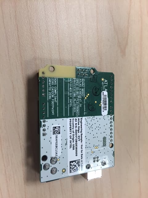
2AB8ZND12
Oct 08, 2015BLE MODULE
Equipment Class
DTS - Digital Transmission System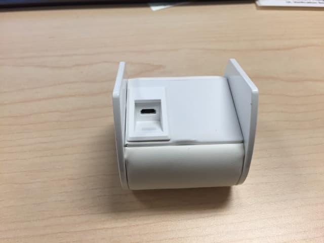
2AB8ZND7
Sep 17, 2015Wireless Charger
Equipment Class
DCD - Part 15 Low Power Transmitter Below 1705 kHz