2AB9W-NFC001NFC Module
XYZprinting, Inc.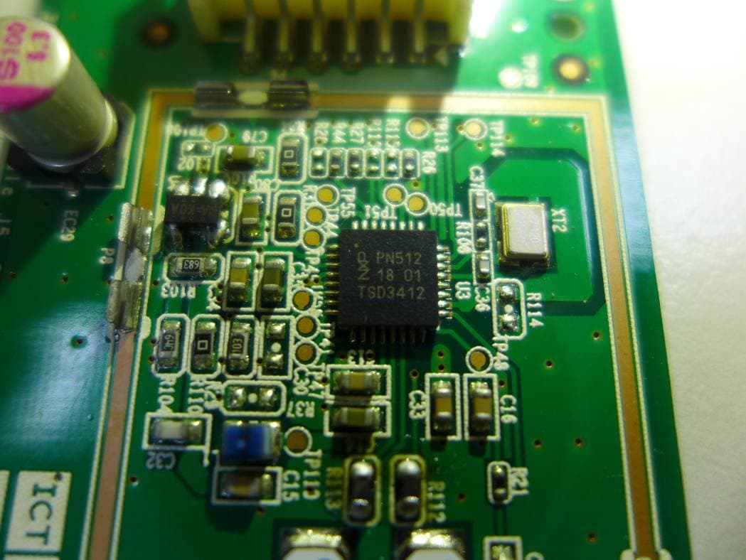
Click to zoom
Application Details
- Equipment Class
- DXX - Part 15 Low Power Communication Device Transmitter
- Date of Grant
- Jul 29, 2015
- Application Purpose
- Original Equipment
- Date of Application
- Jul 28, 2015
- Equipment Note
- NFC Module
- Frequency Range
- 13.56000000 - 13.56000000
- Company
- XYZprinting, Inc.
- Country
- Taiwan
Documents & Files
Document Text
Text extracted from the exhibit documents filed with the FCC. Open a document above to read the original.
Users Manual
NFC Module XYZ‐NFC‐001 Data Sheet Features I2C interface. I 2C-bus interface up to 400 kBd in Fast mode, up to 3400 kBd in High-speed mode FIFO buffer handles 64 byte send and receive Flexible interrupt modes Hard reset with low power function Power-down mode per software Programmable timer Internal oscillator for connection to 27.12 MHz quartz crystal 2.5 V to 5.5 V power supply CRC coprocessor Programmable I/O pins Internal self-test Pin description Pin Symbol Type Description 1 VCC_IN PWR Digital Power Supply 2 GND PWR Digital Ground 3 NRSTPD I Not Reset and Power Down 4 IRQ O Interrupt Request 5 I2C_SDA I/O I2C data 6 I2C_SCL I I2C address Electrical Characteristics Symbol Parameter Min Typ Max Unit VDD digital supply voltage 2.5 5.5 V IDD digital supply current 400 mA Acknowledge An acknowledge must be sent at the end of one data byte. The acknowledge-related clock pulse is generated by the master. The transmitter of data, either master or slave, releases the SDA line (HIGH) during the acknowledge clock pulse. The receiver pulls down the SDA line during the acknowledge clock pulse so that it remains stable LOW during the HIGH period of this clock pulse. The master can then generate either a STOP (P) condition to stop the transfer or a repeated START (Sr) condition to start a new transfer. A master-receiver indicates the end of data to the slave-transmitter by not generating an acknowledge on the last byte that was clocked out by the slave. The slave-transmitter releases the data line to allow the master to generate a STOP (P) or repeated START (Sr) condition. Acknowledge on the I2C-bus Data transfer on the I2C-bus Register read access To read out data from a specific register address in the Module, the host controller must use the following procedure: • Firstly, a write access to the specific register address must be performed as indicated in the frame that follows • The first byte of a frame indicates the device address according to the I2C-bus rules • The second byte indicates the register address. No data bytes are added • The Read/Write bit is 0 After the write access, read access can start. The host sends the device address of the PN512. In response, the Module sends the content of the read access register. In one frame all data bytes can be read from the same register address. This enables fast FIFO buffer access or register polling. The Read/Write (R/W) bit is set to logic 1. Register read and write access I2C-bus timing Federal Communication Commission Interference Statement This equipment has been tested and found to comply with the limits for a Class B digital device, pursuant to Part 15 of the FCC Rules. These limits are designed to provide reasonable protection against harmful interference in a residential installation. This equipment generates, uses and can radiate radio frequency energy and, if not installed and used in accordance with the instructions, may cause harmful interference to radio communications. However, there is no guarantee that interference will not occur in a particular installation. If this equipment does cause harmful interference to radio or television reception, which can be determined by turning the equipment off and on, the user is encouraged to try to correct the interference by one of the following measures: ‐ Reorient or relocate the receiving antenna. ‐ Increase the separation between the equipment and receiver. ‐ Connect the equipment into an outlet on a circuit different from that to which the receiver is connected. ‐ Consult the dealer or an experienced radio/TV technician for help. FCC Caution: Any changes or modifications not expressly approved by the party responsible for compliance could void the user's authority to operate this equipment. This device complies with Part 15 of the FCC Rules. Operation is subject to the following two conditions: (1) This device may not cause harmful interference, and (2) This device must accept any interference received, including interference that may cause undesired operation. FCC Radiation Exposure Statement: This equipment complies with FCC radiation exposure limits set forth for an uncontrolled environment. This transmitter module must not be co‐located or operating in conjunction with any other antenna or transmitter. IMPORTANT NOTE: In the event that these conditions can not be met (for example certain laptop configurations or co‐location with another transmitter), then the FCC authorization is no longer considered valid and the FCC ID can not be used on the final product. In these circumstances, the OEM integrator will be responsible for re‐evaluating the end product (including the transmitter) and obtaining a separate FCC authorization. End Product Labeling: The final end product must be labeled in a visible area with the following: 【Contains FCC ID: 2AB9W‐NFC001】 Manual Information to the End User The OEM integrator has to be aware not to provide information to the end user regarding how to install or remove this RF module in the user’s manual of the end product which integrates this module.
External Photos
Project No.: 1505016 Page 2 of 6 Project No.: 1505016 Page 3 of 6 Project No.: 1505016 Page 4 of 6 Project No.: 1505016 Page 5 of 6 Project No.: 1505016 Page 6 of 6
ID Label/Location Info
Label and Label location
Internal Photos
Project No.: 1505016 Page 2 of 6 Project No.: 1505016 Page 3 of 6 Project No.: 1505016 Page 4 of 6 Project No.: 1505016 Page 5 of 6 Project No.: 1505016 Page 6 of 6
Test Report
Report No.: BTL-FCCP-1-1505016 Page 1 of 31 FCC Radio Test Report FCC ID: 2AB9W-NFC001 This report concerns (check one) : Original Grant Class II Change Project No. : 1505016 Equipment : NFC Module Model Name : XYZ-NFC-001 Applicant : XYZprinting, Inc. Address : 10F., No.99, Sec. 5, Nanjing E. Rd., Songshan Dist., Taipei City 10571, Taiwan (R.O.C.) Date of Receipt : Jun. 04, 2015 Date of Test : Jun. 04, 2015~ Jun. 17, 2015 Issued Date : Jun. 18, 2015 Tested by : BTL Inc. Testing Engineer : (Josh Lin) Technical Manager : (Jeff Yang) Authorized Signatory : (Andy Chiu) BTL INC. B1, No. 37, Lane 365, Yang-guang St., Nei-hu District, Taipei City 114, Taiwan. TEL:+886-2-2657-3299 FAX: +886-2- 2657-3331 Report No.: BTL-FCCP-1-1505016 Page 2 of 31 Declaration BTL represents to the client that testing is done in accordance with standard procedures as applicable and that test instruments used has been calibrated with the standards traceable to National Measurement Laboratory (NML) of R.O.C., or National Institute of Standards and Technology (NIST) of U.S.A. BTL's reports apply only to the specific samples tested under conditions. It is manufacture’s responsibility to ensure that additional production units of this model are manufactured with the identical electrical and mechanical components. BTL shall have no liability for any declarations, inferences or generalizations drawn by the client or others from BTL issued reports. BTL’s report must not be used by the client to claim product certification, approval, or endorsement by NVLAP, NIST, or any agency of the Federal Government. This report is the confidential property of the client. As a mutual protection to the clients, the public and BTL-self, extracts from the test report shall not be reproduced except in full with BTL’s authorized written approval. BTL’s laboratory quality assurance procedures are in compliance with the ISO Guide17025 requirements, and accredited by the conformity assessment authorities listed in this test report. Limitation For the use of the authority's logo is limited unless the Test Standard(s)/Scope(s)/Item(s) mentioned in this test report is (are) included in the conformity assessment authorities acceptance respective. Report No.: BTL-FCCP-1-1505016 Page 3 of 31 Table of Contents REPORT ISSUED HISTORY 5 1 CERTIFICATION 6 2 SUMMARY OF TEST RESULTS 7 2.1 TEST FACILITY 8 2.2 MEASUREMENT UNCERTAINTY 8 3 GENERAL INFORMATION 9 3.1 GENERAL DESCRIPTION OF EUT 9 3.2 DESCRIPTION OF TEST MODES 10 3.3 BLOCK DIAGRAM SHOWING THE CONFIGURATION OF SYSTEM TESTED 11 3.4 DESCRIPTION OF SUPPORT UNITS 11 4 CONDUCTED EMISSION 12 4.1 LIMITS 12 4.2 TEST PROCEDURES 12 4.3 TEST SETUP LAYOUT 13 4.4 DEVIATION FROM TEST STANDARD 13 4.5 EUT OPERATING CONDITIONS 13 4.6 EUT TEST CONDITIONS 13 4.7 TEST RESULTS 13 5 RADIATED EMISSION 14 5.1 LIMITS 14 5.2 TEST PROCEDURE 15 5.3 DEVIATION FROM TEST STANDARD 16 5.4 TEST SETUP 16 5.5 EUT OPERATING CONDITIONS 16 5.6 EUT TEST CONDITIONS 17 5.7 TEST RESULTS (BELOW 30MHZ) - FCC PART 15.209 17 5.8 TEST RESULTS - (30-1000MHZ) - FCC PART 15.209 17 5.9 TEST RESULTS- FCC PART 15.225 17 6 FREQUENCY STABILITY 18 6.1 LIMITS 18 6.2 TEST PROCEDURE 18 6.3 DEVIATION FROM TEST STANDARD 18 6.4 EUT OPERATING CONDITIONS 18 6.5 EUT TEST CONDITIONS 18 6.6 TEST RESULTS 18 7 . MEASUREMENT INSTRUMENTS LIST 19 8 EUT TEST PHOTO 20 ATTACHMENT A - CONDUCTED EMISSION 22 Report No.: BTL-FCCP-1-1505016 Page 4 of 31 Table of Contents ATTACHMENT B - RADIATED EMISSION (9KHZ-30MHZ) 23 ATTACHMENT C - RADIATED EMISSION (30MHZ TO 1000MHZ) 25 ATTACHMENT D - RADIATED EMISSION (FCC PART 15.225) 28 ATTACHMENT E - FREQUENCY STABILITY MEASUREMENT 30 Report No.: BTL-FCCP-1-1505016 Page 5 of 31 REPORT ISSUED HISTORY Issue No. Description Issued Date BTL-FCCP-1-1505016 Original Issue. Jun. 18, 2015 Report No.: BTL-FCCP-1-1505016 Page 6 of 31 1 CERTIFICATION Equipment : NFC Module Brand Name : XYZprinting Model Name : XYZ-NFC-001 Applicant : XYZprinting, Inc. Manufacturer : Cal-Comp Electronics (Thailand) Public Company Limited Address : 138, Moo 4, Phechkasem Road, Sapang, Koawyoi, Petchaburi 76140, Thailand. Factory : Cal-Comp Electronics (Thailand) Public Company Limited Address : 138, Moo 4, Phechkasem Road, Sapang, Koawyoi, Petchaburi 76140, Thailand. Date of Test : Jun. 04, 2015~Jun. 17, 2015 Test Sample : ENGINEERING SAMPLE Standards : FCC Part 15, Subpart C: 2014 ANSI C63.4-2009 The above equipment has been tested and found compliance with the requirement of the relative standards by BTL Inc. The test data, data evaluation, and equipment configuration contained in our test report (Ref No. BTL-FCCP-1-1505016) were obtained utilizing the test procedures, test instruments, test sites that has been accredited by the Authority of TAF according to the ISO-17025 quality assessment standard and technical standard(s). Report No.: BTL-FCCP-1-1505016 Page 7 of 31 2 SUMMARY OF TEST RESULTS Test procedures according to the technical standards: Standard Section Test Item Result 15.207 Conducted emission N/A NOTE(1) 15.35/ 15.205 / 15.209 / 15.225 Radiated emission PASS 15.225(e) Frequency Stability PASS 15.203 Antenna Requirement PASS NOTE: 1. N/A: denotes test is not applicable to this device. Report No.: BTL-FCCP-1-1505016 Page 8 of 31 2.1 TEST FACILITY The test facilities used to collect the test data in this report: Radiated emission Test: CB08: (FCC RN: 614388; FCC DN: TW1054; IC Assigned Code: 4428C-1) 1F., No. 61, Ln. 77, Sing-ai Rd., Neihu Dist., Taipei City 114, Taiwan (R.O.C.) 2.2 MEASUREMENT UNCERTAINTY The measurement uncertainty is not specified by FCC/Industry Canada rules and for reference only. The reported uncertainty of measurement y ±U, where expanded uncertainty U is based on a standard uncertainty multiplied by a coverage factor of k=2, providing a level of confidence of approximately 95%. The measurement instrumentation uncertainty considerations contained in CISPR 16-4-2. The BTL measurement uncertainty is less than the CISPR 16-4-2 U cis…
Text truncated - open the document above for the full version.
Test Setup Photos
Report No.: BTL-FCCP-1-1505016 Page 20 of 31 8 EUT TEST PHOTO Radiated emission test photos 9KHz to 30MHz Report No.: BTL-FCCP-1-1505016 Page 21 of 31 Radiated emission test photos 30MHz to 1000MHz
Contact Information
Applicant
Ren Chen(Deputy Chief Engineer)
Technical Contact
Non-Technical Contact
BTL Inc.Cathy Wang
[email protected]86-769-83183000
Test Firm
BTL Inc.Daisy Dai
Technical Specifications
| # | Rule Parts | Frequency Range | Power Output |
|---|---|---|---|
| 1 | 15C | 13.56 MHz - 13.56 MHz | - |
Other Applications from XYZprinting, Inc.
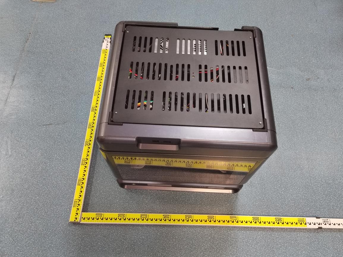
2AB9W-MAX01
Mar 01, 20233D Printer
Equipment Class
DTS - Digital Transmission System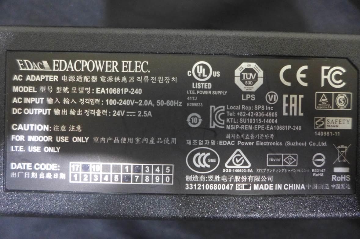
2AB9W-PP150XP
Jan 17, 20203D Printer
Equipment Class
DXX - Part 15 Low Power Communication Device Transmitter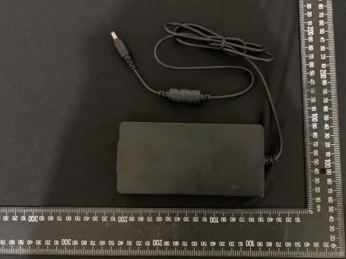
2AB9W-PP120XP
Jan 15, 20203D Printer
Equipment Class
DTS - Digital Transmission System
2AB9W-3F1J0
Mar 19, 20153D Printer
Equipment Class
DXX - Part 15 Low Power Communication Device Transmitter
2AB9W-3F1JW
Mar 19, 20153D Printer
Equipment Class
DXX - Part 15 Low Power Communication Device Transmitter