2ABC6C6F76AC001UMa Wireless Charger
MCNEX CO.,LTD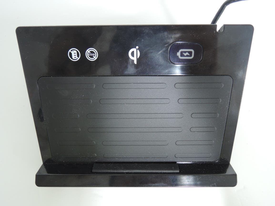
Click to zoom
Application Details
- Equipment Class
- DCD - Part 15 Low Power Transmitter Below 1705 kHz
- Date of Grant
- Oct 01, 2014
- Application Purpose
- Original Equipment
- Date of Application
- Oct 01, 2014
- Equipment Note
- UMa Wireless Charger
- Frequency Range
- 0.11000000 - 0.20500000
- Company
- MCNEX CO.,LTD
- Country
- South Korea
Documents & Files
Document Text
Text extracted from the exhibit documents filed with the FCC. Open a document above to read the original.
Users Manual
This product was designed for Kia Motors’ UM Only Qi‐certified device can be charged on this product. CHARGER ASSY‐WIRELESS UMA C6F76‐AC001/010 User’s Manual UMa Wireless Charger Revision Date 11/09/2014 Page 1of 5 Description of parts ᄆaᄆ NOTE Qi Logo: This product is Qi‐certified wireless charger. No Smart Key: Do not put a smart key on this product. No Coins: Do not put the coins on this product. Thanks for purchasing KIA Motors’ UMA Vehicle wireless charger. Please read this manual carefully and use the product safely. UMa Wireless Charger Revision Date 11/09/2014 Page 2of 5 How to use 1. Start the vehicle 2. Put the Qi certified device on the center of charging pad. 3. LED lamp will turn in red when charging started. • In order to prevent interference, do not put any other object between charging pad and mobile phone. UMa Wireless Charger Revision Date 11/09/2014 Page 3of 5 Troubleshooting Caution, Service Charging is not processing. ‐Check if the device is placed on the pad correctly. ‐Check if the device is Qi certified. ‐Check if there is any object between charging pad and device. LED is blinking ‐Check if the device is placed on the pad correctly. ‐Check if there is any metal object (ex: coins) between charging pad and device. Do not put smart key or coins on the pad, Do not spill water or any other fluids on the product. Maintain enough distance from other objects that can be affected by magnetic field. 1. Place the mobile phone on the center of this charging pad. If it is not placed on the correct place, charging could be processed abnormally. 2. It is recommended to use genuine Rx CASE for this product. Use of abnormal Rx CASE may cause mal‐operation or damage to the product. 3. Placing coin or metal object in between the pad and charging device may cause burn or body injury accident by heat. Stop using product and call the store you purchased for help if any problem occurs during the use of product. UMa Wireless Charger Revision Date 11/09/2014 Page 4of 5 Compliance Statement FCC Compliance Statement This device complies with part 15 of the FCC Rules. Operation is subject to the following two conditions : (1) This device may not cause harmful interference, and (2) This device must accept any interference received, including interference that may cause undesired operation. This equipment has been tested and found to comply with the limits for a Class B digital device, pursuant to Part 15 of the FCC Rules. These limits are designed to g provide reasonable protection against harmful interference in a residential installation. This equipment generates uses and can radiate radio frequency energy and, if not installed and used in accordance with the instructions, may cause harmful interference to radio communications. However, there is no guarantee that interference will not occur in a particular installation. If this equipment does cause harmful interference to radio or television reception, which can be determined by turning the equipment off and on, the user is encouraged to try to correct the interference by one or more of the following measures: – Reorient or relocate the receiving antenna. –Increase the separation between the equipment and receiver. – Connect the equipment into an outlet on a circuit different from that to which the receiver is connected. –Consult the dealer or an experienced radio/TV technical for help. IC Compliance Statement This device complies with Industry Canada license‐exempt RSS standard(s). Operation is subject to the following two conditions: (1) this device may not cause interference, and (2) this device must accept any interference, including interference that may cause undesired operation of the device. Cet appareil est conforme avec Industrie Canada exempts de licence standard RSS (s). L'opération est soumise aux deux conditions suivantes: (1) cet appareil ne peut causer d'interférences, et (2) cet appareil doit accepter toute interférence, y compris les interférences quipeuvent causer un mauvais fonctionnement de l'appareil. User’s Caution Statement Any changes or modifications to the equipment not expressly approved by the party responsible for compliance could void user’s authority to operate the equipment. Toute changé ou modifications non expressément approuvés parla partie responsable de la conformité pourraient annuler l'utilisateur `autorité de faire fonctionner cet équipement. CE Hereby, MCNEX CO., LTD.declares that this C6F76AC001is in compliance with the essential requirements and other relevant provisions of directive 1999/5/EC . UMa Wireless Charger Revision Date 11/09/2014 Page 5of 5 C6F76AC001/AC010 Rated Input VoltageDC 12V 1ARated Output VoltageDC 5V 1A Operational Temperature ‐40 °C ~ 80 °C CertificationQi, CE, FCC, IC Product Specification ProductUMa Wireless ChargerModel UMa Wireless Charger Revision Date 11/09/2014 Page 5of 5
Cover Letter(s)
SCS-F18: Project and Product Certification Representative Authorization Letter Page 1 of 3 Rev 4.0 775 Montague Expressway Milpitas, CA 95035 Tel: 408-526-1188 Fax: 408-526-1088 Email: [email protected] Project and Product Certification Representative Authorization Letter Reason for Amendment (current / obsolete) Revision History Approved Date From To Initial Release (obsolete) 1.0 1.0 Nov-14-2006 Revised wording (obsolete) 1.0 2.0 Sept–25-2007 Updated company template (obsolete) 2.0 3.0 Jan-31-2012 Updated letter information (current) 3.0 4.0 May-23-2014 SCS-F18: Project and Product Certification Representative Authorization Letter Page 2 of 3 Rev 4.0 Sep. 19, 2014 To: SIEMIC, INC. 775 Montague Expressway, Milpitas, CA 95035 USA Dear Sir/Madam, Re: Product Certification Representative Authorization Letter We, MCNEX CO., LTD. hereby authorize SIEMIC, Inc. to act as a Certification Body for certifying for the following project(s): (UMa Wireless Charger, C6F76AC001, C6F76AC010) Sincerely, Gi-ho, Kim Manager MCNEX CO., LTD. Hanshin IT Tower 2, 60-18, Gasan-dong, Geumcheon-gu, Seoul, Korea
Cover Letter(s)
SCS-F19: Confidentiality Request Letter Page 1 of 3 Rev 3.0 775 Montague Expressway Milpitas, CA 95035 Tel: 408-526-1188 Fax: 408-526-1088 Email: [email protected] Confidentiality Request Letter Reason for Amendment (current / obsolete) Revision History Approved Date From To Initial Release (obsolete) 1.0 1.0 Nov-14-2006 Adding CFR 2.459 (obsolete) 1.0 2.0 August – 11 - 2008 Updated company template & Added text box (current) 2.0 3.0 Jan-31-2012 SCS-F19: Confidentiality Request Letter Page 2 of 3 Rev 3.0 Sep. 19, 2014 To: Federal Communications Commission Authorization and Evaluation Division 7435 Oakland Mills Road Columbia, MD Subject: Permanent Confidentiality Request for FCC ID: 2ABC6C6F76AC001 We hereby request confidential treatment of information accompanying this application as outlined below: - e.g. Block Diagram - e.g. Schematics - e.g. Operational Description - e.g. Part List The above materials contain trade secrets and proprietary information not customarily released to the public. The public disclosure of these materials may be harmful to the applicant and provide unjustified benefits to its competitors. The applicant understands that pursuant to Section 0.457 & 0.459 of the Rules, disclosure of this application and all accompanying documentation will not be made before the date of the Grant for this application. Sincerely, Client’s signature : Client’s name / title : Gi-ho, Kim / Manager Contact information / address: 82-70-8630-6924 / Hanshin IT Tower 2, 60-18, Gasan-dong, Geumcheon-gu, Seoul, Korea SCS-F19: Confidentiality Request Letter Page 3 of 3 Rev 3.0 Sep. 19, 2014 To: Federal Communications Commission Office of Engineering and Technology Equipment Authorization Division 7345 Oakland Mills Road Columbia, Maryland 21046 Subject: Short Term Confidentiality Request for FCC ID: 2ABC6C6F76AC001 To Whom It May Concern: Pursuant to sections 0.457 and 0.459 of CFR 47 and to avoid premature release of sensitive information prior to marketing or release of the product to the public, the applicant requests the following documents contained in this certification application be temporarily withheld from public disclosure for an initial period of 45 or 180 days (please check one). - e.g. User Manual - e.g. Ext Photo - e.g. Int Photo - e.g. Test Photo The above materials contain trade secrets and proprietary information not customarily released to the public. The public disclosure of these materials may be harmful to the applicant and provide unjustified benefits to its competitors. Sincerely, Client’s signature : Client’s name / title : Gi-ho, Kim / Manager Contact information / address: 82-70-8630-6924 / Hanshin IT Tower 2, 60-18, Gasan-dong, Geumcheon-gu, Seoul, Korea
Cover Letter(s)
MCNEX CO., LTD. Hanshin IT Tower 2, 60-18, Gasan-dong, Geumcheon-gu, Seoul, Korea Date: Sep. 19, 2014 SIEMIC 775 Montague Expressway Milpitas, CA 95035 Tel: 408-526-1188 Fax: 408-526-1088 Email: [email protected] Letter of Authorization We, the undersigned, hereby authorize Harvey Sung of DT&C Co., Ltd. to act on our behalf in all manners relating to application for equipment authorization for FCCID: 2ABC6C6F76AC001 including signing of all documents relating to these matters. Any and all acts carried out by Harvey Sung of DT&C Co., Ltd. on our behalf shall have the same affect as acts of our own. This authorization is valid until further written notice from MCNEX CO., LTD. “I, the undersigned, hereby certify that we are not subject to a denial of federal benefits, that includes FCC benefits, pursuant to Section 5301 of the Anti-Drug Abuse Act of 1988, 21 U.S.C. 853(a).” Sincerely, Gi-ho, Kim Manager
Cover Letter(s)
Company Letter head Date: Sep 22, 2014 To: Federal Communications Commission 7435 Oakland Mills Road Columbia, MD FCC ID: 2ABC 6CF76AC001 To Whom It May Concern: This letter is to ascertain that MCNEX CO.,LTD Product Wireless charging pad 2ABC 6CF76AC001, has been the units used for conducting FCC compliance testing, and it meets KDB 680106 Clause 5(2) all 6 conditions as stated below hence PBA is not required. 1 Power transfer frequency is less that 1 MHz The power transfer frequency of DUT(Device Under Test) is between 110kHz and 205kHz. 2 Output power from each primary coil is less than 5 watts Output power from each coils are Max. 5 watts. 3 The transfer system includes only single primary and secondary coils. This includes charging systems that may have multiple primary coils and clients that are able to detect and allow coupling only between individual pairs of coils The DUT are consist of 3 charging coils using A6 coils as below so the DUT can detect and allow coupling only between individual pairs of coils 4 Client device is inserted in or placed directly in contact with the transmitter When the client device is placed directly in contact with transmitter, then charging is able to start. 5 The maximum coupling surface area of the transmit (charging) device is between 60 cm2 and 400 cm2. The Maximum coupling surface area of the charging transmit is 75㎠. 6 Aggregate leakage fields at 10 cm surrounding the device from all simultaneous transmitting coils are demonstrated to be less than 30% of the MPE limit. The highest leakage filed is less than 30 % of the MPE limit. If you have any question or concerns, pls. contact us. Sincerely, Client’s signature Name: Gi-ho, Kim Address: Hanshin IT Tower II, 11F, 60-18, Gasan-dong, Geumcheon-gu, Seoul, KOREA
External Photos
FCCID: 2ABC6C6F76AC001 Copyright Ⓒ 2014, DT&C Co., Ltd. Page 1 / 3 View 1 FCCID: 2ABC6C6F76AC001 Copyright Ⓒ 2014, DT&C Co., Ltd. Page 2 / 3 View 2 FCCID: 2ABC6C6F76AC001 Copyright Ⓒ 2014, DT&C Co., Ltd. Page 3 / 3 View 3
ID Label/Location Info
FCC ID: 2ABC6C6F76AC001 Copyright Ⓒ 2014, DT&C Co., Ltd. FCC ID SAMPLE LABEL & LOCATION LABELLING REQUIREMENTS PER §2.925 The Label shown shall be permanently affixed at a conspicuous location on the device and be readily visible to the user at the time of purchase Label locate bottom side - The FCC label shown is representative of the label that will appear on the radio when in production. Other information may also be included on this user manual
Internal Photos
FCCID: 2ABC6C6F76AC001 Copyright Ⓒ 2014, DT&C Co., Ltd. Page 1 / 4 View 1 FCCID: 2ABC6C6F76AC001 Copyright Ⓒ 2014, DT&C Co., Ltd. Page 2 / 4 View 2 FCCID: 2ABC6C6F76AC001 Copyright Ⓒ 2014, DT&C Co., Ltd. Page 3 / 4 View 3 FCCID: 2ABC6C6F76AC001 Copyright Ⓒ 2014, DT&C Co., Ltd. Page 4 / 4 View 4
RF Exposure Info
DEMC1407-03093 FCC ID : 2ABC6C6F76AC001 DRTFCC1409-1205 TRF-RF-220(00)131220 Page2 / 7 Copyright ○ C 2014, DT&C Co., Ltd. Test Report Version Test Report No. Date Description DRTFCC1409-1205 Sep. 22, 2014 Initial issue DEMC1407-03093 FCC ID : 2ABC6C6F76AC001 DRTFCC1409-1205 TRF-RF-220(00)131220 Page3 / 7 Copyright ○ C 2014, DT&C Co., Ltd. CONTENTS 1. Equipment information ............................................................................ 4 1.1 Equipment description ........................................................................... 4 1.2 Support equipment................................................................................. 4 2. Information about test items ................................................................... 5 2.1 Test Configuration and Mode ................................................................. 5 2.2 Tested environment ................................................................................ 5 3. E and H field strength .............................................................................. 6 DEMC1407-03093 FCC ID : 2ABC6C6F76AC001 DRTFCC1409-1205 TRF-RF-220(00)131220 Page4 / 7 Copyright ○ C 2014, DT&C Co., Ltd. 1. Equipment information 1.1 Equipment description FCC Equipment Class Part 15 Low Power Transmitter Below 1705 kHz (DCD) Equipment type UMa Wireless Charger Equipment model name C6F76AC001 Equipment add model name C6F76AC010 Equipment serial no. Identical prototype Frequency range 110 ~ 205 kHz Output power Max : 5 W Power DC 12V Antenna type Coil Antenna X 3ea Note Note: This device has 3 coil antennas but only one antenna is used for transmitting at a time after selection of the best coil antenna, 1.2 Support equipment Equipment Model No. Serial No. Manufacturer Note Wireless Charging Cover MWC-R511T 0943 M.Cloud - Note: The supporting equipments were supported by manufacturer. DEMC1407-03093 FCC ID : 2ABC6C6F76AC001 DRTFCC1409-1205 TRF-RF-220(00)131220 Page5 / 7 Copyright ○ C 2014, DT&C Co., Ltd. 2. Information about test items 2.1 Test Configuration and Mode ▪Test configuration The field strength of both E-field and H-field were measured at 10 cm using RF exposure survey meter with E-field and H- field probes for determining compliance with the MPE requirements of FCC Part 1.1310 During measurements, the wireless charging pad (EUT) was wirelessly charging a battery housed inside a portable handset and was loaded with the client device using the resistor as described below summary table for test modes and conditions. The RF power density was measured with the battery at 2 different charge conditions: battery at almost 0 % and 50 % status, 3 resistive load conditions: 300 mA, 500 mA, 1000 mA (Max. charging current with 5 Ω resister). These testing were performed at test configuration as test setup diagram on clause 3 of this test report. EUT was placed on a non-conductive turntable, and the portable handset with charging cover for charging a battery or client device with resistive load for drawing various load current. This device uses a wireless charging circuit for power transfer operating at the frequency of 110 KHz ~ 205 KHz. Thus, the 300 KHz RF exposure limits were used as below table. ▪Test mode This device has been tested in all the configuration of charging mode in each coil antennas. Test Mode Charging Current Support Equipment 1 100mA Wireless Charging Cover (M/N: MWC-R511T) 2 500mA 3 1000mA(Max) ▪ Limit Frequency E-Field limit H-Field limit FCC Part 1.1310 300 KHz ~ 3MHz 614 V/m 1.63 A/m 2.2 Tested environment Temperature : 22 ~ 23°C Relative humidity content : 36 ~ 38 % R.H. Details of power supply : DC 12 V DEMC1407-03093 FCC ID : 2ABC6C6F76AC001 DRTFCC1409-1205 TRF-RF-220(00)131220 Page6 / 7 Copyright ○ C 2014, DT&C Co., Ltd. 3. E and H field strength For RF exposure purposes, the E and H field strengths are measured separately with E and H probes and meters at different locations surrounding the test setup. ▪ Test setup diagram Note: For desktop charger like this device, Z-axis were not tested since top and bottom side of the desktop charger shall be separated far from the human body in actual usage condition. ▪ Measurement distance information Measurement distance = 10cm (From EUT edge to the center of probe) ▪ Measurement procedure These testing were performed at test configuration as above diagram. EUT was placed on a turntable, and the measurement probe was placed at a measurement distance of 10 cm from the EUT, the turn table was rotated 360 degrees to capture the highest signal. ▪Test equipment list Type Manufacturer Model Cal.Date (yy/mm/dd) Next. Cal.Date (yy/mm/dd) S/N Magnetic Field Meter Holaday Industries HI-3627 14/01/09 16/01/09 23776 Electric Field Meter Combinova EFM200 14/01/20 16/01/20 185(N2443) - - - - - - - DEMC1407-03093 FCC ID : 2ABC6C6F76AC001 DRTFCC1409-1205 TRF-RF-220(00)131220 Page7 / 7 Copyright ○ C 2014, DT&C Co., Ltd. ▪ Measurement data: Coil1 Tested Frequency Result Limit E-field(V/m) H-field(A/m) E-field(V/m) H-field(A/m) 0 90 180 270 0 90 180 270 Lowest 4.22 5.74 6.49 4.24 0.48 0.20 0.13 0.20 614 1.63 Middle 4.28 5.12 5.03 3.92 0.44 0.26 0.20 0.24 Highest 4.90 5.11 7.13 5.68 0.32 0.15 0.15 0.16 Note : The worst case data were reported.
Test Report
DEMC1407-03093 FCC ID : 2ABC6C6F76AC001 DRTFCC1409-1206 TRF-RF-204(01)110221 Page 2 / 13 Copyright ○ C 2014, DT&C Co., Ltd. Test Report Version Test Report No. Date Description DRTFCC1409-1206 Sep. 22, 2014 Initial issue DEMC1407-03093 FCC ID : 2ABC6C6F76AC001 DRTFCC1409-1206 TRF-RF-204(01)110221 Page 3 / 13 Copyright ○ C 2014, DT&C Co., Ltd. CONTENTS 1. Equipment information ............................................................. 4 1.1 Equipment description ............................................................ 4 1.2 Support equipments ............................................................... 4 2. Information about test items .................................................... 5 2.1 Test mode ............................................................................... 5 2.2 Tested environment ................................................................ 5 2.3 EMI Suppression Device(s)/Modifications .............................. 5 3. FACILITIES AND ACCREDITATIONS ........................................ 6 3.1 FACILITIES ............................................................................ 6 3.2 EQUIPMENT .......................................................................... 6 4. Test Report ................................................................................ 7 4.1 Summary of tests ................................................................... 7 4.2 Transmitter requirements........................................................ 8 4.2.1 20dB Bandwidth ................................................................. 8 4.2.2 Radiated Emissions ........................................................... 9 4.2.3 AC Line Conducted Emissions .......................................... 11 APPENDIX I ................................................................................. 12 DEMC1407-03093 FCC ID : 2ABC6C6F76AC001 DRTFCC1409-1206 TRF-RF-204(01)110221 Page 4 / 13 Copyright ○ C 2014, DT&C Co., Ltd. 1. Equipment information 1.1 Equipment description FCC Equipment Class Part 15 Low Power Transmitter Below 1705 kHz (DCD) Equipment type UMa Wireless Charger Equipment model name C6F76AC001 Equipment add model name C6F76AC010 Equipment serial no. Identical prototype Frequency band 110 ~ 205 kHz Output power Max : 5 W Power DC 12V Antenna type Coil Antenna X 3ea Note Note: This device has 3 coil antennas but only one antenna is used for transmitting at a time after selection of the best coil antenna,. 1.2 Support equipments Equipment Model No. Serial No. Manufacturer Note Wireless Charging Cover MWC-R511T 0943 M.Cloud - Note: The above equipments were supported by manufacturer. DEMC1407-03093 FCC ID : 2ABC6C6F76AC001 DRTFCC1409-1206 TRF-RF-204(01)110221 Page 5 / 13 Copyright ○ C 2014, DT&C Co., Ltd. 2. Information about test items 2.1 Test mode This device has been tested in all the configurations of charging mode with each coil antenna. Charging Current Support Equipment 100mA Wireless Charging Cover 500mA 1000mA(Max) 2.2 Tested environment Temperature : 23 ~ 24 o C Relative humidity content : 35 ~ 42 % R.H. Details of power supply : DC 12 V 2.3 EMI Suppression Device(s)/Modifications EMI suppression device(s) added and/or modifications made during testing → None DEMC1407-03093 FCC ID : 2ABC6C6F76AC001 DRTFCC1409-1206 TRF-RF-204(01)110221 Page 6 / 13 Copyright ○ C 2014, DT&C Co., Ltd. 3. FACILITIES AND ACCREDITATIONS 3.1 FACILITIES The semi anechoic chamber and conducted measurement facility used to collect the radiated and conducted test data are located at the 42, Yurim-ro, 154beon-gil, Cheoin-gu, Yongin-si, Gyeonggi-do, Korea 449-935. The site is constructed in conformance with the requirements. - Semi anechoic chamber registration Number: FCC (596748), IC (5740A-2) 3.2 EQUIPMENT Radiated emissions are measured with one or more of the following types of antennas: loop, tuned dipole, bi-conical, log periodic, bi-log, and/or ridged waveguide horn. Spectrum analyzers with pre-selectors and peak, quasi-peak detectors are used to perform radiated measurements. Conducted emissions are measured with Line Impedance Stabilization Networks and EMI Test Receivers. Calibrated wideband preamplifiers, coaxial cables, and coaxial attenuators are also used for making measurements. All receiving equipment conforms to CISPR Publication 16-1, “Radio Interference Measuring Apparatus and Measurement Methods.” DEMC1407-03093 FCC ID : 2ABC6C6F76AC001 DRTFCC1409-1206 TRF-RF-204(01)110221 Page 7 / 13 Copyright ○ C 2014, DT&C Co., Ltd. 4. Test Report 4.1 Summary of tests FCC Part Section(s) Parameter Limit Test Condition Status Note 1 Test Items 2.1049 20 dB Bandwidth N/A Radiated C 15.209 Radiated Emission FCC 15.209 limits C 15.207 AC Conducted Emissions FCC 15.207 limits AC Line Conducted NA Note2 Note 1: C=Comply NC=Not Comply NT=Not Tested NA=Not Applicable Note 2: The supplying power of this device is DC 12V from a Car Battery. The sample was tested according to the following specification: ANSI C-63.4 2009 DEMC1407-03093 FCC ID : 2ABC6C6F76AC001 DRTFCC1409-1206 TRF-RF-204(01)110221 Page 8 / 13 Copyright ○ C 2014, DT&C Co., Ltd. 4.2 Transmitter requirements 4.2.1 20dB Bandwidth - Procedure: The 20 dB bandwidth is measured with a spectrum analyzer connected via a receiving antenna placed near the EUT while the EUT is operating. - Measurement Data: Charging Current 1000 mA DEMC1407-03093 FCC ID : 2ABC6C6F76AC001 DRTFCC1409-1206 TRF-RF-204(01)110221 Page 9 / 13 Copyright ○ C 2014, DT&C Co., Ltd. 4.2.2 Radiated Emissions - Limit: FCC Part 15.209(a) Frequency [MHz] Field Strength [uV/m] Measurement Distance [Meters] 0.009 ~ 0.490 2400/F(kHz) 300 0.490 ~ 1.705 24000/F(kHz) 30 1.705 ~ 30 30 30 30 ~ 88 100 3 88 ~ 216 150 3 216 ~ 960 200 3 Above 960 500 3 ** Except as provided in 15.209(g), fundamental emissions from intentional radiators operating under this Section shall not be located in the frequency bands 54-72 MHz, 76-88MHz, 174-216MHz or 470-806MHz. However, op…
Text truncated - open the document above for the full version.
Test Setup Photos
FCC ID: 2ABC6C6F76AC001 Copyright Ⓒ 2014, DT&C Co., Ltd. Test Setup Photo for Radiated Emissions FCC ID: 2ABC6C6F76AC001 Copyright Ⓒ 2014, DT&C Co., Ltd. Test Setup Photo for RF Exposure
Contact Information
Applicant
SEUNG JUN RO(Senior Research Engineer)
Test Firm
DT&C Co.,Changho Lee
Technical Specifications
| # | Rule Parts | Frequency Range | Power Output |
|---|---|---|---|
| 1 | 15C | 0.11 MHz - 0.205 MHz | - |
Other Applications from MCNEX CO.,LTD
2ABC6-M8ULTRA
Jun 10, 20262CH Dashcam
Equipment Class
DTS - Digital Transmission System
2ABC6MNC-H200
May 13, 2015NETWORK IP CAMERA
Equipment Class
DTS - Digital Transmission System
2ABC64CH58AP000
Dec 30, 2013Wireless Charger
Equipment Class
DCD - Part 15 Low Power Transmitter Below 1705 kHz