2ABLP-VSC10024GHz Satcom Road Speed Detector/Commercial Vehicles
ViaSat, Inc.
Click to zoom
Application Details
- Equipment Class
- DXX - Part 15 Low Power Communication Device Transmitter
- Date of Grant
- May 07, 2014
- Application Purpose
- Original Equipment
- Date of Application
- May 07, 2014
- Equipment Note
- 24GHz Satcom Road Speed Detector/Commercial Vehicles
- Frequency Range
- 24158.80000000 - 24158.80000000
- Company
- ViaSat, Inc.
- Country
- United States
Documents & Files
Document Text
Text extracted from the exhibit documents filed with the FCC. Open a document above to read the original.
Users Manual
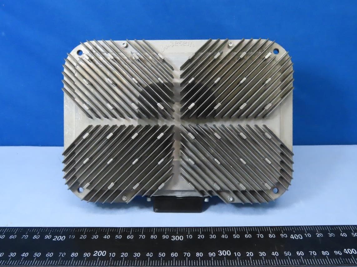
- 1 - VELOCITY SENSING CONTROLLER MODEL 100 (VSC100) OWNER’S MANUAL ViaSat - Digital Communication Products and Services for Commercial and Government Markets - 2 - ViaSat, Incorporated Advanced Microwave Products 1388 North Tech Blvd. Gilbert, AZ 8533 Office: +1 480-503-5505 Fax: +1 480-503-5501 ViaSat, Inc. Headquarters 6155 El Camino Real Carlsbad, CA 92009 Copyright 2014 © ViaSat, Inc. All rights reserved. No part of this work may be reproduced, published, or distributed in any form or by any means (electronically, mechanically, photocopying, recording, or otherwise), or stored in a database retrieval system, without the prior written permission of ViaSat Incorporated in each instance. - 3 - Table of Contents TABLE OF CONTENTS ............................................................................................................................. 3 DOCUMENT REVISION HISTORY ........................................................................................................ 3 1 INTRODUCTION ................................................................................................................................ 4 2 PRECAUTIONS ................................................................................................................................... 4 3 PRODUCT DESCRIPTION ................................................................................................................ 4 4 INSTALLATION ................................................................................................................................. 5 5 CONNECTOR ...................................................................................................................................... 6 Document Revision History Version Date Author Contributors Change Tracker Description 001 12/23/13 D. Saunders Initial Release Status: (click appropriate checkbox) Document No: 1183141 Initial Draft Version: 001 Working Draft Date: 12/23/13 Pilot Released Revision to Released - 4 - 1 Introduction These instructions provide important information to the users of the ViaSat Velocity Sensing Controller Model 100, or VSC100. By following these instructions, the VSC100 will function properly over its lifetime. If these instructions are not followed, the VSC100 may malfunction and/or have a limited lifetime. 2 Precautions All installation, adjustment, or removal of the VSC100 should be undertaken by trained personnel who are trained in safety regulations for the system. This device complies with Part 15 of the FCC rules and carries the FCC ID is 2ABLP- VSC100. Operation is subject to the following two conditions: (1) this device may not cause harmful interference, and (2) this device must accept any interference received, including interference that may cause undesired operation. Any unauthorized changes or modifications to the VSC100 could void the user’s authority to operate the equipment in the system. 3 Product Description The VSC100 includes an environmentally protective metal housing and plastic cover with wire harness as shown in Figure 1. Figure 1 – VSC100 - 5 - The VSC works using the Doppler principal. The sensor is pointed toward a road surface and transmits energy, some of which is scattered back to the VSC and received. If there is motion of the VSC with respect to the scatterers on the road surface, the received frequency will be offset from the transmitted frequency directly proportional to the velocity of the relative motion. As shown in Figure 2, the received frequency for motion "away" from the scatterers causes a decrease in frequency, while motion "toward" the scatterers causes an increase in frequency. The VSC100 measurement of frequency also depends on the installation angle with respect to the horizon, so care must be taken to ensure proper installation. R a d a r S e n s o r Road Surface Frequency Tx Motion Rx Motion Rx Figure 2 – Velocity Sensing Using Doppler 4 Installation The VSC100 typically mounts 1 meter above the ground on a bracket firmly attached to the under structure of the vehicle. It is oriented so that the plastic cover is pointing towards the rear of the vehicle at an angle of 30 degrees with respect to horizontal with the cable harness tied so that it does not obstruct the path from the VSC100 to the ground, as shown below in Figure 3. - 6 - Figure 3 – VSC100 Mounting 5 Connector The VSC100 connector is shown below in Figure 4. Figure 4 – VSC100 Connector When used in a system, the VSC100 is connected to a 12 volt power system, an indicator light, and two electromechanical latches. The wiring diagram is shown below in Figure 5. - 7 - Figure 5 – Wiring Harness
Cover Letter(s)
Page 1 of 2 FCC ID: 2ABLP-VSC100 IC ID: CT Project:P13b0005 From: Shawn McMillen Date: 5/1/14 1. The internal photos only show one side of the PCB. There is however a portion of the PCB showing in the external photos but this appears to be insufficient, DW – Requested internal photos from Nathan on 5/2/14 2. The test report should reference compliance to 15.203 by way of an integral antenna. CT –15.203 has been added to the test report. The antenna is internal. 3. The test report should reference compliance to 15.214(c), the 20dB bandwidth. CT –15.215(c) has been referenced within the test summary on page 6 of the Test Report. The plots associated with 15.249 show compliance with 15.215(c) 4. The test report shows two plots at of emissions at the band edge. Please identify if these two plots are intended to meet the requirements below 15.247(d) Emissions radiated outside of the specified frequency bands, except for harmonics, shall be attenuated by at least 50 dB below the level of the fundamental or to the general radiated emission limits in §15.209, whichever is the lesser attenuation CT – The plots have been further detailed as 15.249(d) within the Test Report. CT - Response by: Submitted by: Date: Page 2 of 2
ID Label/Location Info
2.000 1.000 2X .082 1.008.090.902 1 2 4 5 6 8 7 REVISIONS (ALL SHEETS AT SAME REVISION) REVDESCRIPTIONDATE 001RELEASE PER REQ-057316 2013-12-19 MANUFACTURING FILES DESCRIPTIONFILENAME 2D DXF FILE 1182859_REV001.DXF 2D DRAWING 1182859_REV001.PDF 2 CAD GENERATED DRAWING: SHEET 1 OF UNLESS OTHERWISE SPECIFIED CAGE CODE DESCRIPTION SCALE: DRAWING NO. SIZE D REV DRAWN 1 DATE PROJECT D C B A 345678 A B C D 4567 48EU8 8 1 Corona 2013-12-19 1182859 1 NONE 001 N. WELBORNE DIMENSIONS ARE IN INCHES AND APPLY AFTER FINISH OR PLATING. TOLERANCES ARE: .000-.250 .251-.500 .501-1.000 +.004 -.001 PROPRIETARY NOTICE THESE DRAWINGS, LISTS OR SPECIFICATIONS ARE THE CONFIDENTIAL INFORMATION AND/OR TRADE SECRETS OF VIASAT, INC., AND ISSUED IN STRICT CONFIDENCE. EXCEPT AS AUTHORIZED BY VIASAT IN WRITING, THESE DRAWINGS, LISTS OR SPECIFICATIONS SHALL NOT BE REPRODUCED, RETRANSMITTED, USED FOR THE DESIGN, MANUFACTURE OR SALE OF EQUIPMENT OR USED FOR ANY OTHER PURPOSE OTHER THAN EVALUATION. PART NO: 1182859 32 ELECTRONIC APPROVALS ON FILE IN AGILE SOLIDWORKS LABEL, VSC MODULE, PRE- PRODUCTION, 2"X1" THIRD ANGLE PROJECTION HOLE DIAMETER +.006 -.001 +.010 -.001 MAX SURFACE ROUGHNESS 125 MICROINCHES RMS ON ALL MACHINED SURFACES NOTES: 1388 N. TECH BLVD SUITE 1 GILBERT, AZ 85233 SEE SEPARATE PARTS LIST(S) ENVIRONMENTAL COMPLIANCE FINISHED PART TO BE RoHS AND REACh COMPLIANT PER EU DIRECTIVE 2002/95/EC AND EU REGULATION 1907/2006 AND SHALL NOT USE OZONE DEPLETING SUBSTANCES PER US REGULATORY REQUIREMENTS. FABRICATOR SHALL ADD A UNIQUE PERMANENT IDENTIFICATION MARK IN ACCORDANCE WITH E-QAPP PR000608 “FABRICATOR FACILITY MARKING”. MATERIAL DECLARATIONS FOR RoHS AND REACH(SVHC'S) SHALL BE PROVIDED AND UPDATED AS NEEDED IN ACCORDANCE WITH THE REQUIREMENTS OF PR000608. REACH SVHC DECLARATION UPDATES SHALL BE FORWARDED TO: [email protected] ± .1 ± .01 ±.005 ±.005 ± .5°MACHINING: ± .1 ± .03 ±.010 ±.010 ± .5° .X .XX .XXX NON-DIM ANGULAR SHEET METAL: THIS TECHNICAL DATA IS SUBJECT TO THE UNITED STATES EXPORT ADMINISTRATION REGULATIONS. DIVERSION CONTRARY TO U.S. LAW IS PROHIBITED. INTERPRET DIMENSIONS AND TOLERANCES PER ASME Y14.5-2009.1. MATERIAL:2. 2.1 BASE STOCK, BRADY LABEL P/N B33-17-428 (POLYESTER, THERMAL TRANSFER PRINTABLE, MATTE SILVER, 2"X1"X.003") 2.2 INK: BRADY LABEL P/N B30-R6000 (BLACK THERMAL TRANSFER RIBBON) LABEL TEXT AND GRAPHICS TO BE BLACK AND OPAQUE, AND PLACED 3. APPROXIMATELY WHERE SHOWN. ALL CHARACTERS SHALL USE FONT TYPE TAHOMA, HEIGHT TO BE .060 INCHES 4. MINIMUM. LINEAR BAR CODES SHALL BE CODE 128 PER ANSI/AIM BC1-1995, WIDTH RATIO 1:2. PART NO.: POPULATE "YYYYYYY" WITH APPLICABLE VIASAT PART NUMBER AS 5. SHOWN IN AGILE. POPULATE "XXX" WITH APPLICABLE REVISION OF "YYYYYYY" ASSEMBLY AS INDICATED IN AGILE. LINEAR BARCODE SHALL CONTAIN THE FOLLOWING INFORMATION: 6. YYYYYYYXXX WHERE YYYYYYY AND XXX ARE DETERMINED PER NOTE 5. S/N: POPULATE SSSSSSS WITH SEVEN-DIGIT MODULE SERIAL NUMBER, AS 7. DETERMINED AT TIME OF MANUFACTURE. BARCODE SHALL CONTAIN SAME DATA. VIASAT LOGO SHALL BE GENERATED USING THE 2D ELECTRONIC DATA 8. ATTACHED IN AGILE. IDENTIFY LABEL WITH LABEL PART NUMBER AND REVISION. DO NOT MARK 9. PART. BAG AND TAG. PACKAGE LABEL TO ENSURE PROTECTION FROM CONTAMINATION AND 10. DAMAGE RESULTING FROM HANDLING, STORAGE, OR SHIPPING. IDENTIFICATION SHALL BE PER NOTE 9.
Test Report
p13b0005_FCC_Part 15.249_Rev 2.0 Page 1 of 14 Test Report Prepared for: ViaSat Model: VSC100 Description: Velocity Sensing Controller 100 - True Ground Speed/Direction with Single Speed Trigger for deploying aerodynamic features on trailers FCC ID: 2ABLP-VSC100 To FCC Part 15.249 Date of Issue: December 19, 2013 On the behalf of the applicant: ViaSat 1388 N Tech Blvd Gilbert, AZ 85233 Attention of: Daryl Hunter, Corporate Regulations Engineer Ph: (760) 476-2583 E-mail: [email protected] And Dave Saunders, Senior Systems Engineer Ph: (480) 503-5594 E-mail: [email protected] Prepared by Compliance Testing, LLC 1724 S. Nevada Way Mesa, AZ 85204 (480) 926-3100 phone / (480) 926-3598 fax www.compliancetesting.com Project No: p13b0005 Alex Macon Project Test Engineer This report may not be reproduced, except in full, without written permission from Compliance Testing. All results contained herein relate only to the sample tested. p13b0005_FCC_Part 15.249_Rev 2.0 Page 2 of 14 Test Report Revision History Revision Date Revised By Reason for Revision 1.0 December 19, 2013 Alex Macon Original Document 2.0 May 1, 2014 Alex Macon Added detail to band edge plots, added specification 15.215(c) to the test summary table, and added specification 15.203 p13b0005_FCC_Part 15.249_Rev 2.0 Page 3 of 14 Table of Contents Description Page Standard Test Conditions Engineering Practices ............................................................................................. 6 Test Results Summary ..................................................................................................................................... 8 Fundamental Field Strength ............................................................................................................................. 9 Radiated Spurious Emissions ......................................................................................................................... 11 99% Occupied Bandwidth ............................................................................................................................... 13 Test Equipment Utilized .................................................................................................................................. 14 p13b0005_FCC_Part 15.249_Rev 2.0 Page 4 of 14 ILAC / A2LA Compliance Testing, LLC, has been accredited in accordance with the recognized International Standard ISO/IEC 17025:2005. This accreditation demonstrates technical competence for a defined scope and the operation of a laboratory quality management system (refer to joint ISO-ILAC-IAF Communiqué dated January 2009). The tests results contained within this test report all fall within our scope of accreditation, unless noted below. Please refer to http://www.compliancetesting.com/labscope.html for current scope of accreditation. Testing Certificate Number: 2152.01 FCC Site Reg. #349717 IC Site Reg. #2044A-2 Non-accredited tests contained in this report: N/A p13b0005_FCC_Part 15.249_Rev 2.0 Page 5 of 14 The applicant has been cautioned as to the following 15.21: Information to User The user’s manual or instruction manual for an intentional radiator shall caution the user that changes or modifications not expressly approved by the party responsible for compliance could void the user’s authority to operate the equipment. 15.27(a): Special Accessories Equipment marketed to a consumer must be capable of complying with the necessary regulations in the configuration in which the equipment is marketed. Where special accessories, such as shielded cables and/or special connectors are required to enable an unintentional or intentional radiator to comply with the emission limits in this part, the equipment must be marketed with, i.e. shipped and sold with, those special accessories. However, in lieu of shipping or packaging the special accessories with the unintentional or intentional radiator the responsible part may employ other methods of ensuring that the special accessories are provided to the consumer, without an additional charge. Information detailing any alternative method used to supply the special accessories for a grant of equipment authorization or retained in the verification records, as appropriate. The party responsible for the equipment, as detailed in § 2.909 of this chapter, shall ensure that these special accessories are provided with the equipment. The instruction manual for such devices shall include appropriate instructions on the first page of text concerned with the installation of the device that these special accessories must be used with the device. It is the responsibility of the user to use the needed special accessories supplied with the equipment. p13b0005_FCC_Part 15.249_Rev 2.0 Page 6 of 14 Standard Test Conditions Engineering Practices Except as noted herein, the following conditions and procedures were observed during the testing. In accordance with ANSI C63.10-2009 and unless otherwise indicated in the specific measurement results, the ambient temperature of the actual EUT was maintained within the range of 10° to 40°C (50° to 104°F) unless the particular equipment requirements specify testing over a different temperature range. Also, unless otherwise indicated, the humidity levels were in the range of 10% to 90% relative humidity. Measurement results, unless otherwise noted, are worst-case measurements. Environmental Conditions Temperature (°C) Humidity (%) Pressure (mbar) 19.9 - 20.3 30.5 – 31.8 971.5 - 975.3 EUT Description Model: VSC100 Description: Velocity Sensing Controller 100 - True Ground Speed/Direction with Single Speed Trigger for deploying aerodynamic features on trailers Additional Information: The EUT is a 24GHz Satcom Road Speed Detector used on commercial vehicles. EUT Operation during Tests EUT was placed in normal operation with the final cable harness 15.203: Antenna Requirement: X The antenna is permanently attached to the EUT The antenna uses a unique coupling …
Text truncated - open the document above for the full version.
Test Setup Photos
Test Setup Photos FCC ID: 2ABLP-VSC100 RF Radiated #1 RF Radiated #2
Contact Information
Applicant
Daryl T Hunter(Director, Regulatory Affairs)
Test Firm
Compliance Testing, LLCMichael Schafer
Technical Specifications
| # | Rule Parts | Frequency Range | Power Output |
|---|---|---|---|
| 1 | 15C | 24.16 GHz - 24.16 GHz | 6.00 µW |
Other Applications from ViaSat, Inc.
2ABLPRX3000
Aug 03, 2022Blackbird Ka-Band Transceiver
Equipment Class
DTS - Digital Transmission System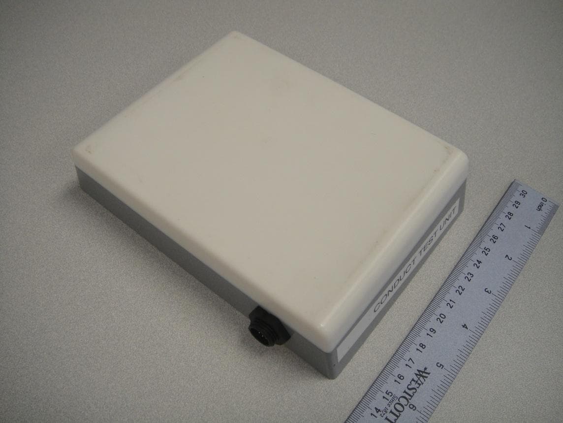
2ABLPFT2225
Nov 11, 2015Fixed L-Band satellite modem with WLAN and Bluetooth
Equipment Class
DSS - Part 15 Spread Spectrum Transmitter