2ABM5W-SWR1Wi-Fi Audio Receiver
Zhong Shan City LI TAI Electronic Industrial Co., Ltd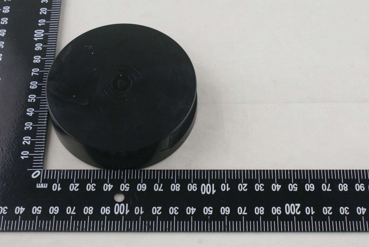
Click to zoom
Application Details
- Equipment Class
- DSS - Part 15 Spread Spectrum Transmitter
- Date of Grant
- Jul 15, 2015
- Application Purpose
- Original Equipment
- Date of Application
- Jul 15, 2015
- Equipment Note
- Wi-Fi Audio Receiver
- Frequency Range
- 2402.00000000 - 2480.00000000
- Country
- China
Documents & Files
Document Text
Text extracted from the exhibit documents filed with the FCC. Open a document above to read the original.
Users Manual
HITACHI AllPlay Adaptor User’s Guide HITACHI Allplay Adaptor User`s Guide 1 Contents IMPORTANT SAFETY INSTRUCTIONS ......................................... 2 Product Layout ......................................................................... 4 LED Indicators ........................................................................... 5 Hitachi Wi‐Fi Speaker App ......................................................... 5 ※Preparation ........................................................................... 6 Wi‐Fi input setup ...................................................................... 6 1.Using a mobile device for Wi‐Fi setup ................................. 6 2. Using WPS (Wi‐Fi Protected Setup) .................................... 7 Playing music ............................................................................ 8 1. Home network .................................................................. 8 2. Grouping Speakers (Party Mode) ....................................... 9 3. Online music services ...................................................... 10 4. Using Spotify ................................................................... 11 5. Using online music services other than Spotify ................ 11 Bluetooth Setup ...................................................................... 13 Firmware updates ................................................................... 14 Adaptor IP & MAC address ...................................................... 16 Troubleshooting ..................................................................... 18 Resetting the AllPlay Adaptor to factory default ..................... 19 Specifications .......................................................................... 20 HITACHI Allplay Adaptor User`s Guide 2 IMPORTANT SAFETY INSTRUCTIONS 1) Read these instructions. 2) Keep these instructions. 3) Heed all warnings. 4) Follow all instructions. 5) Do not use this apparatus near water. 6) Clean only with dry cloth. 7) Do not block any ventilation openings. Install in accordance with the manufacturer’s instructions. 8) Do not install near any heat sources such as radiators, heat registers, stoves, or ot her apparatus (including amplifiers) that produce heat. 9) Do not defeat the safety purpose of the polarized or grounding‐type plug. A polarized plug has two blades with one wider than the other. A grounding type plug has two blades and a third groun ding prong. The wide blade or the third prong are provided for your safety. If the provided plug does not fit into your outlet, consult an electrician for replacement of the obsolete outlet. 10) Protect the power cord from being walked on or pinched particularly at plugs, convenience receptacles, and th e point where they exit from the apparatus. 11) Only use attachments/accessories specified by the manufacturer. 12) Use only with cart, stand, tripod, bracket, or table specified by the manufacturer, or sold with the apparatus. When a cart is used, use caution when moving the cart/apparatus combination to avoid injury from tip‐over. 13 ) Unplug this apparatus during lightning storms or when unused for long periods of time. 14) Refer all servicing to qualified service personnel. Servicing is required when the apparatus has been damaged in any way, such as power‐supply cord or plug is damaged, liquid has been spilled or obje cts have fallen into the apparatus, the apparatus has been exposed to rain or moisture, does not operate normally, or has been dropped. HITACHI Allplay Adaptor User`s Guide 3 15) Apparatus should not be exposed to dripping or splashing, and objects filled with liquids, such as vases, should not be placed on the apparatus. 16) Do not overload wall outlets and extension cords, as this can result in a risk of fire or electric shock. 17) Do not push objects thro ugh any openings in this unit, as they may touch dangerous voltage points or short out parts that could result in fire or electric shock. Never spill or spray any type of liquid into the unit. 18) When replacement parts are required, be sure the service technician uses replacement parts specified by the manufacturer or those that have the same characteristics as the original part. Unauthorized substitutions may result in fire, electric shock or other hazards. 19) The mains plug is used as the disconnect and shall rem ain readily operable. 20) Only use the AC adapters that are included with this product. HITACHI Allplay Adaptor User`s Guide 4 Product Layout 1, LED: Indicates Wi‐Fi and BT source selected. 2, WPS button: Press to enter Wi‐Fi setup mode (Access Point Mode); Press for 2s to enter WPS mode. 3, SOURCE button: Press to select the input source.(Wi‐Fi/BT) 4, AUX: AUX output jack (3.5mm). 5, DC IN: Power s upply input. 6, RESET hole: reset the AllPlay Adaptor to factory default setting. 1 2 3 4 5 6 HITACHI Allplay Adaptor User`s Guide 5 LED Indicators The table below explains the behavior and status of your speaker’s LED indicators. LED Behavior LED Flash Frequency Working Status White LED and Blue LED alternately flashing 4HzPower on White LED slow flash1HzEnter Wi‐Fi connecting or disconnection mode White LED fast flashing 4HzEnter Wi‐Fi pairing mode with WPS method White LED Solid SolidWi‐Fi connected Blue LED fast flash 4HzEnter BT pairing mode Blue LED Solid SolidBT connected Hitachi WI‐FI Speaker App Use the Hitachi Wi‐Fi Speaker App to control your Smart Wi‐Fi Speaker. Search using the keywords “Hitachi Wi‐Fi Speaker” and download the app from the Apple ® App Store (iPhone®/iPad®) or Google Play TM store (Android devices). * Requires smartphone or tablet running Apple® iOS (V6, 7, 8) or Android TM OS (V2.2 through V4. HITACHI Allplay Adaptor User`s Guide 6 ※Preparation: Before you use your AllPlay Adaptor to playing music, connect speakers with 3.5mm line through the AUX hole. Wi‐Fi input setup You can stream music to your speaker from a mobile device on your Wi‐Fi network by using the “H…
Text truncated - open the document above for the full version.
Cover Letter(s)
ZhongShanCityLITAIElectronicIndustrialCo.,Ltd Date:July16,2015 To:FederalCommunicationsCommission, Authorization&EvaluationDivision, 7435OaklandMillsRoad, Columbia,MD21046 ToWhomItMayConcern: TheZhongShanCityLITAIElectronicIndustrialCo.,Ltd,theundersigned, hereby,confirmsthattheWi-Fimodulecontainedinthisdeviceiselectrically identicaltothecertifiedmoduleFCCID:PPD-CUS227listedontheFCCwebsite, andthattheantennagainisthesameasinapprovedmodule. Signatory: Printedname:YukiCai
Cover Letter(s)
ZhongShanCityLITAIElectronicIndustrialCo.,Ltd Date:09July,2015 To:FederalCommunicationsCommission, Authorization&EvaluationDivision, 7435OaklandMillsRoad, Columbia,MD21046 Re:ZhongShanCityLITAIElectronicIndustrialCo.,Ltd FCCID:2ABM5W-SWR1 FCCCertificationConfidentialityRequest Gentlemen: Thisletteristocomplywith47CFR0.457and0.459pertainingto confidentialitymaterial.ZhongShanCityLITAIElectronicIndustrialCo.,Ltd requeststhatthefollowingdocumentsregardingthissubmissionforFCCID: 2ABM5W-SWR1bekeptconfidential: ExhibitTypeFileName BlockDiagramBlockDiagram.pdf CircuitdiagramCircuitdiagram.pdf OperationalDescriptionOperationalDescription.pdf Thosedocumentscontaindetailedsystemandequipmentdescriptionandrelated informationabouttheproductwhichZhongShanCityLITAIElectronicIndustrial Co.,Ltdconsiderstobeconfidentialproprietary,acustomdesignand,otherwise, notreleasabletothegeneralpublic.Sincethisdesignisabasisformwhichfuture technologicalproductswillevolve,ZhongShanCityLITAIElectronicIndustrial Co.,Ltdconsidersthisinformationwouldbeofbenefittoitscompetitors,andthat thedisclosureoftheinformationinthesedocumentswouldgivecompetitorsan unfairadvantageinthemarket. YoursSincerely, YukiCai
Cover Letter(s)
ZhongShanCityLITAIElectronicIndustrialCo.,Ltd Date:09July,2015 To:FederalCommunicationsCommission, Authorization&EvaluationDivision, 7435OaklandMillsRoad, Columbia,MD21046 ToWhomItMayConcern: TheZhongShanCityLITAIElectronicIndustrialCo.,Ltd,theundersigned, herebyauthorizesMr.WuXuewenfromShenzhenBalunTechnologyCo.,Ltd.,to actonthebehalfoftheZhongShanCityLITAIElectronicIndustrialCo.,Ltdsolely inmattersrelatingtotheapplicationforanFCCequipmentauthorizationforFCC ID#:2ABM5W-SWR1includingthesigningofdocumentsinconnectionwiththis Application.NecessaryactscarriedoutbyShenzhenBalunTechnologyCo.,Ltd. onourbehalfoftheZhongShanCityLITAIElectronicIndustrialCo.,Ltdin connectionwiththeApplicationshallhavethesameeffectasactsoftheZhong ShanCityLITAIElectronicIndustrialCo.,Ltd.TheZhongShanCityLITAI ElectronicIndustrialCo.,Ltdalsoherebycertifythatnopartytothisapplicationis subjecttoadenialofbenefits,includingFCCbenefits,pursuanttoSection5301of theAnti-DrugAbuseActof1988,21U.S.C.853(a). Thankyouforyourattentiontothismatter. YoursSincerely, YukiCai
External Photos
ANNEX C EUT PHOTOS C.1 Appearance of the EUT THE FRONT OF EUT THE BACK OF EUT 2 / 4 THE LEFT OF EUT THE RIGHT OF EUT 3 / 4 THE UP OF EUT THE DOWN OF EUT 4 / 4 CHARGER
ID Label/Location Info
Label: Label_location:
Internal Photos
ANNEX C EUT PHOTOS C.2 Inside of the EUT EUT UNCOVER VIEW 1 、 EUT UNCOVER VIEW 2 2 / 6 EUT UNCOVER VIEW 3 MAIN BOARD TOP VIEW 1 3 / 6 MAIN BOARD BACK VIEW 1 MAIN BOARD TOP VIEW 2 4 / 6 MAIN BOARD TOP VIEW 3 MAIN BOARD BACK VIEW 3 BT Chip PCB Antenna 5 / 6 MAIN BOARD TOP VIEW 4 MAIN BOARD BACK VIEW 4 6 / 6 MAIN BOARD TOP VIEW 5
RF Exposure Info
RF Exposure Evaluation For FCC ID: 2ABM5W-SWR1 Refer user manual this device is a Wi-Fi Audio Receiver, and this device was designed used in Mobile devices that the minimum distance between human’s body is 20cm. Based on the 47CFR 2.1091, this device belongs to Mobile device. The definition of the category as following: Mobile Derives: CFR Title 47 §2.1091(b) (b) For purposes of this section, a mobile device is defined as a transmitting device designed to be used in other than fixed locations and to generally be used in such a way that a separation distance of at least 20 centimeters is normally maintained between the transmitter’s radiating structure(s) and the body of the user or nearby persons. FCC KDB 447498 D01 General RF Exposure Guidance v05r02 Limit Devices operating in standalone mobile exposure conditions may contain a single transmitter or multiple transmitters that do not transmit simultaneously. A minimum test separation distance ≥ 20 cm is required between the antenna and radiating structures of the device and nearby persons to apply mobile device exposure limits. The distance must be fully supported by the operating and installation configurations of the transmitter and its antenna(s), according to the source-based time-averaged maximum power requirements of § 2.1091(d)(2). In cases where cable losses or other attenuations are applied to determine compliance, the most conservative operating configurations and exposure conditions must be evaluated. The minimum test separation distance required for a device to comply with mobile exposure conditions must be clearly identified in the installation and operating instructions, for all installation and exposure conditions, to enable users and installers to comply with RF exposure requirements. For mobile devices that have the potential to operate in portable device exposure conditions, similar to the configurations described in § 2.1091(d)(4), a KDB inquiry is required to determine the SAR test requirements for demonstrating compliance. When the categorical exclusion provision of § 2.1091(c) applies, the minimum test separation distance may be estimated, when applicable, by simple calculations according to plane-wave equivalent conditions, to ensure the transmitter and its antenna(s) can operate in manners that meet or exceed the estimated distance. The source-based time-averaged maximum radiated power, according to the maximum antenna gain, must be applied to calculate the field strength and power density required to establish the minimum test separation distance. When the estimated test separation distance becomes overly conservative and does not support compliance, MPE measurement or computational modeling may be used to determine the required minimum separation distance. RF Exposure Evaluation Result: FCC (Worst case) According to FCC Part 1.1307, systems operating under the provisions of this section shall be operated in a manner the ensures that the public is not exposed to radio frequency energy level in excess of the commission’s guidelines. Limits for General Population/ Uncontrolled Exposure Frequency Range (MHz) Electric Field Strength(E)(V/m) Magnetic Field Strength (H)(A/m) Power Density (S)(mW/cm2) 0.3-1.34 614 1.63 (100)* 1.34-30 824/f 2.19/f (180/f2)* 30-300 27.5 0.073 0.2 300-1500 f/1500 1500-100,000 1.0 MPE calculation formula 푺= 푷푮 ퟒ흅푹 ퟐ Where: S = power density P = output power (W) G = power gain of the antenna in the direction of interest relative to an isotropic radiator R = Separation distance between radiator and human body (m) Test result Blutooth Maximum peak output power at antenna input terminal(dBm): 6.97 Maximum peak output power at antenna input terminal(mW): 4.98 Prediction distance(cm): 20 Predication frequency(MHz): 2480 Antenna Gain (typical) (dBi): 0 Power density at predication frequency at 20 cm(mW/cm2): 0.001 MPE limit for RF exposure at prediction frequency(mW/cm2): 1 2.4G WLAN Maximum peak output power at antenna input terminal(dBm): 23.86 Maximum peak output power at antenna input terminal(mW): 243.414 Prediction distance(cm): 20 Predication frequency(MHz): 2437 Antenna Gain (typical) (dBi): 5.01 Power density at predication frequency at 20 cm(mW/cm2): 0.15349 MPE limit for RF exposure at prediction frequency(mW/cm2): 1 5G WLAN Maximum peak output power at antenna input terminal(dBm): 25.80 Maximum peak output power at antenna input terminal(mW): 379.840 Prediction distance(cm): 20 Predication frequency(MHz): 5745 Antenna Gain (typical) (dBi): 6.01 Power density at predication frequency at 20 cm(mW/cm2): 0.30153 MPE limit for RF exposure at prediction frequency(mW/cm2): 1 FCC Verdict: PASS Note: 1. The Wi-Fi Audio Receiver work frequency range used is 2400 MHz to 2483.5 MHz for Bluetooth, 2412 MHz to 2472 MHz for 2.4G WLAN, 5180 MHz to 5240 MHz, 5260 MHz to 5320 MHz and 5500 MHz to 5700 MHz for 5G WLAN. And when bluetooth works at 2480MHz, 2.4G WLAN works at 2437MHz, and 5G WLAN works at 5745MHz, the result close to the limit by the above formula, so we select these frequency to calculate the exclusion power threshold. 2. More power list please refer to RF test report.
Test Report
Report No.: BL-SZ1550058-601 2 Revision History Version Issue Date Revisions Rev. 01 May. 25, 2015 Initial Issue TABLE OF CONTENTS 1 ADMINISTRATIVE DATA (GENERAL INFORMATION) ........................................................................ 6 1.1 Identification of the Testing Laboratory ..................................................................................... 6 1.2 Identification of the Responsible Testing Location .................................................................... 6 1.3 Announce ................................................................................................................................. 6 2 PRODUCT INFORMATION ................................................................................................................... 7 2.1 Applicant .................................................................................................................................. 7 2.2 Manufacturer ............................................................................................................................ 7 2.3 General Description for Equipment under Test (EUT) ............................................................... 7 2.4 Technical Information ............................................................................................................... 7 2.5 Ancillary Equipment .................................................................................................................. 8 3 SUMMARY OF TEST RESULTS ........................................................................................................... 9 3.1 Test Standards ......................................................................................................................... 9 3.2 Verdict ...................................................................................................................................... 9 4 GENERAL TEST CONFIGURATIONS ................................................................................................ 10 4.1 Test Environments .................................................................................................................. 10 4.2 Test Equipment List ................................................................................................................ 10 4.3 Test Configurations ................................................................................................................ 11 4.4 Description of Test Setup ....................................................................................................... 11 4.4.1 For Antenna Port Test ............................................................................................................ 11 4.4.2 For AC Power Supply Port Test .............................................................................................. 12 4.4.3 For Radiated Test (Below 30 MHz) ......................................................................................... 12 4.4.4 For Radiated Test (30 MHz-1 GHz) ........................................................................................ 13 4.4.5 For Radiated Test (Above 1 GHz) .......................................................................................... 13 4.5 Test Conditions ...................................................................................................................... 14 Report No.: BL-SZ1550058-601 3 4.6 Measurement Results Explanation Example ........................................................................... 15 4.6.1 For conducted test items: ....................................................................................................... 15 4.6.2 For radiated band edges and spurious emission test: ............................................................. 15 TEST ITEMS ....................................................................................................................................... 16 5 5.1 Antenna Requirements ........................................................................................................... 16 5.1.1 Standard Applicable ............................................................................................................... 16 5.1.2 Antenna Anti-Replacement Construction ................................................................................ 16 5.1.3 Antenna Gain ......................................................................................................................... 16 5.2 Number of Hopping Frequency ............................................................................................... 17 5.2.1 Limit........................................................................................................................................ 17 5.2.2 Test Procedure ....................................................................................................................... 17 5.2.3 Test Setup .............................................................................................................................. 17 5.2.4 Test Result ............................................................................................................................. 17 5.3 Peak Output Power ................................................................................................................ 18 5.3.1 Test Limit ................................................................................................................................ 18 5.3.2 Test Procedure ....................................................................................................................... 18 5.3.3 Test Setup .............................................................................................................................. 18 5.3.4 Test Result ............................................................................................................................. 18 5.4 Occupied Bandwidth ..…
Text truncated - open the document above for the full version.
Test Setup Photos
ANNEX B TEST SETUP PHOTOS B.1 Conducted Test Photo B.2 Conducted Emissions Test Photo B.3 Radiated Test Photo Below 30 MHz 30 MHz to 1 GHz Above 1 GHz
Contact Information
Applicant
yaohui tang(Safety approbation engineer)
Test Firm
Shenzhen BALUN Technology Co.,Ltd.Xuewen Wu
Technical Specifications
| # | Rule Parts | Frequency Range | Power Output |
|---|---|---|---|
| 1 | 15C | 2.40 GHz - 2.48 GHz | 3.95 mW |
Other Applications from Zhong Shan City LI TAI Electronic Industrial Co., Ltd
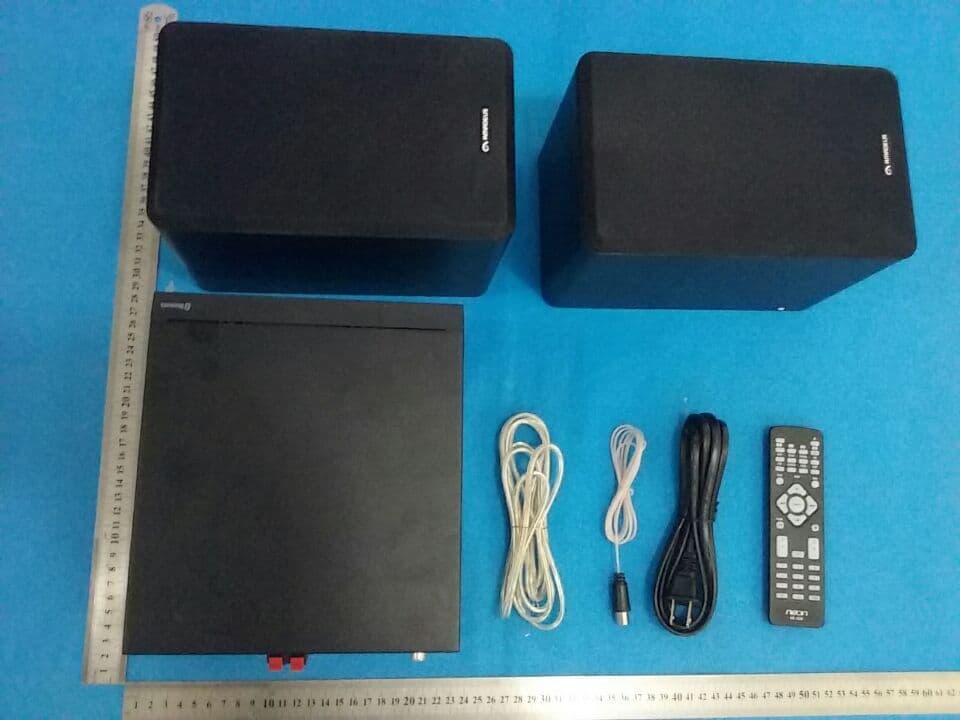
2ABM5-MCB1536
Nov 24, 2015CD MICRO SYSTEM
Equipment Class
DTS - Digital Transmission System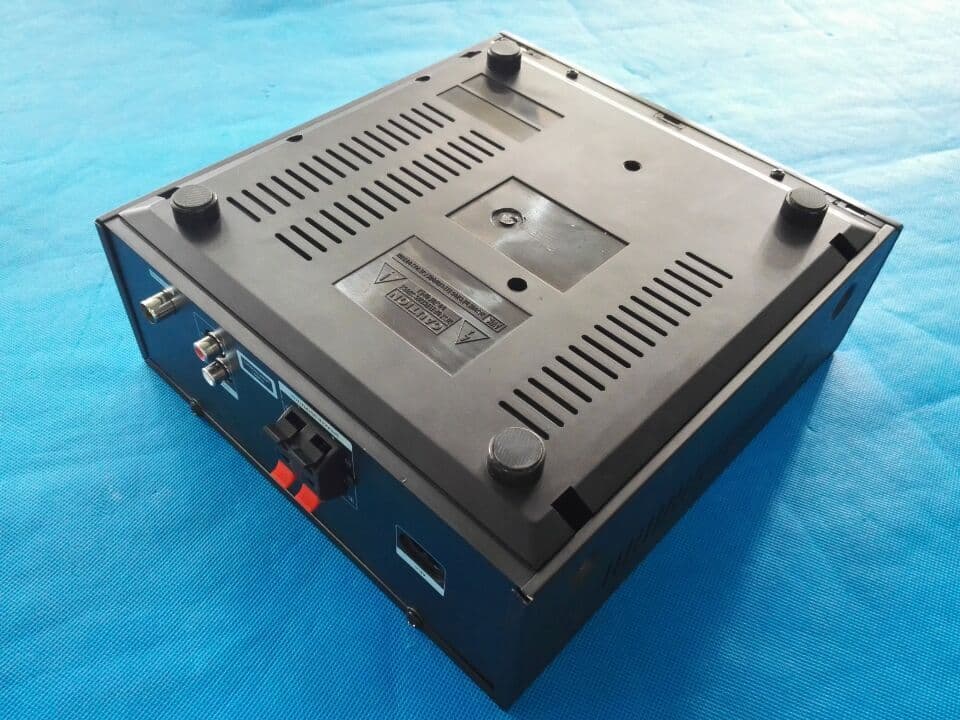
2ABM5-MCB1515
Nov 04, 2015CD MICRO SYSTEM
Equipment Class
DSS - Part 15 Spread Spectrum Transmitter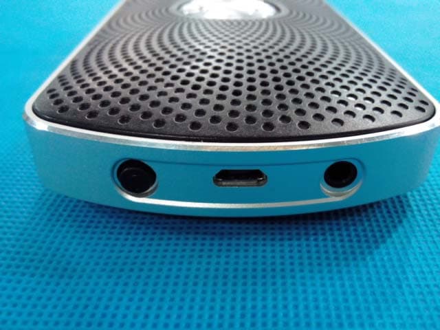
2ABM5-BTS510
Aug 23, 2015Bluetooth Speaker
Equipment Class
DSS - Part 15 Spread Spectrum Transmitter2ABM5W-200
Mar 26, 2015Wi-Fi Speaker System
Equipment Class
DSS - Part 15 Spread Spectrum Transmitter2ABM5W-100
Mar 25, 2015Wi-Fi Speaker System
Equipment Class
DSS - Part 15 Spread Spectrum Transmitter