2ABRU-BLEM203DBDE Bluetooth 5 Low Energy Modul
Guangzhou BDE Technology Inc.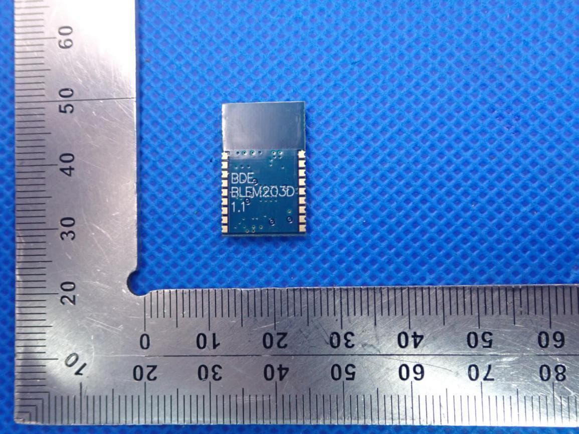
Click to zoom
Application Details
- Equipment Class
- DTS - Digital Transmission System
- Date of Grant
- Aug 05, 2020
- Application Purpose
- Original Equipment
- Date of Application
- Aug 05, 2020
- Equipment Note
- BDE Bluetooth 5 Low Energy Modul
- Frequency Range
- 2402.00000000 - 2480.00000000
- Country
- China
Documents & Files
Document Text
Text extracted from the exhibit documents filed with the FCC. Open a document above to read the original.
Users Manual
BDE Technology Inc. BDE-BLEM203D BDE Technology Co., Ltd. Bluetooth Low Energy Module (BT5.0) Key Features Bluetooth 5.0 single-mode compliant Support master and slave modes, 8 simultaneous connections in master mode Integrated Bluetooth Low Energy stack, no external MCU needed RF performance TX power: -21dBm to 5dBm RX sensitivity: up to -96dBm Communication range: 250 meters (LOS) – Long Range Mode Ultra low power ARM Cortex-M3 microcontroller core Antenna: PCB Size: 20.5 mm x 13 mm x 1.5mm (Without Shielding) 20.5 mm x 13 mm x 2.1 mm (With Shielding) Ultra low power consumption: Shutdown: 150nA (Wake up on external events) Standby: 1.1uA (RTC running and RAM/CPU retention) BQB (QDID: 151462), FCC (FCC ID: 2ABRU-BLEM203D), CE, RoHS compliant Descriptions BDE-BLEM203D is a Bluetooth 5.0 single-mode compliant Bluetooth low energy module targeted at low power sensors and PC/Phone accessories. BDE-BLEM203D highly integrates Bluetooth Low Energy radio, stack, profile and applications in a SoC, without the need of using an external MCU. The module also offers flexible hardware interfaces for the sensor application. It enables ultra-low power connectivity and data transfer for the applications that are sensitive to power consumption, size and cost. BDE Technology Inc. BDE-BLEM203D BDE Technology Co., Ltd. Block Diagram Fig. 1: The Block Diagram of BDE-BLEM203D Applications Medical devices Sports and fitness equipment Home electronics Mobile and PC accessories Industry automation BDE Technology Inc. BDE-BLEM203D BDE Technology Co., Ltd. Electrical Characteristics Absolute maximum rating Rating Min Typ Max Unit Storage Temperature -40 - 125 °C VDDS -0.3 - 4.1 V Other Digital Terminals -0.2 - VDDS+0.3≤4.1 V Recommended operating conditions Rating Min Typ Max Unit Operating Temperature -40 - 85 °C VDDS 1.8 3.3 3.8 V Overall Dimensions Fig. 2 shows the overall dimensions of BDE-BLEM203D. The module measures 20.5mm long by 13mm wide by 1.5mm high without the shield. Fig. 2: Overall Dimensions of BDE-BLEM203D (BOTOM VIEW) BDE Technology Inc. BDE-BLEM203D BDE Technology Co., Ltd. Pin Definitions Fig. 3: The pinout of BDE-BLEM203D (TOP VIEW) Table 1: Pin definitions of BDE-BLEM203D Pin Number Pin Name Definitions 1 GND Power Ground 2 DIO_0 GPIO, Sensor Controller, high-drive capability 3 DIO_1 GPIO, Sensor Controller, high-drive capability 4 DIO_2 GPIO, Sensor Controller, high-drive capability 5 JTAG_TMS JTAG_TMS 6 JTAG_TCK JTAG_TCK 7 DIO_3 GPIO, High-drive capability, JTAG_TDO 8 DIO_4 GPIO, High-drive capability, JTAG_TDI 9 VDDS Power Supply 10 RESET Reset, Active-low 11 DIO_5 GPIO, Sensor Controller, Analog 12 DIO_6 GPIO, Sensor Controller, Analog 13 DIO_7 GPIO, Sensor Controller, Analog 14 DIO_8 GPIO, Sensor Controller, Analog 15 DIO_9 GPIO, Sensor Controller, Analog 16 GND Power Ground 17 NC NC 18 GND Power Ground BDE Technology Inc. BDE-BLEM203D BDE Technology Co., Ltd. Module Location In order to get a fine performance when integrate the module to your product, it is advised to use the recommended module location to the respective PCB. Location in X-Y plane Fig. 4: Recommended location in X-Y plane Fig. 5: Not recommended location in X-Y plane BDE Technology Inc. BDE-BLEM203D BDE Technology Co., Ltd. Location in Z plane Fig. 6: Recommended location in Z plane Fig. 7: Not recommended location in Z plane BDE Technology Inc. BDE-BLEM203D BDE Technology Co., Ltd. Typical Solder Reflow Profile Fig. 7: Typical Solder Reflow Profile Package Information Fig. 8: Package information BDE Technology Inc.BDE-BLEM203D BDE Technology Co., Ltd. Integration Instructions Integration instructions for host product manufacturers according to KDB 996369 D03 OEM Manual v01 2.2 List of applicable FCC rules FCC Part 15.247 2.3 Specific operational use conditions This transmitter/module and its antenna must not be co-located or operating in conjunction with any transmitter. This information also extends to the host manufacturer’s instruction manual. 2.4 Limited module procedures Not applicable. 2.5 Trace antenna designs Not applicable. 2.6 RF exposure considerations This equipment complies with FCC RF radiation exposure limits set forth for an uncontrolled environment. This compliance to FCC radiation exposure limits for an uncontrolled environment, and minimum of 5mm separation between antenna and body. The host product manufacturer would provide the above information to end users in their end-product manuals. 2.7 Antennas Integral Antenna: 1.15 dBi, 2.4 GHz~2.5 GHz 2.8 Label and compliance information The end product must carry a physical label or shall use e-labelling followed KDB784748D01 and KDB 784748 stating “Contains Transmitter Module FCC ID: 2ABRU-BLEM203D”. 2.9 Information on test modes and additional testing requirements For more information on testing, please contact the manufacturer. 2.10 Additional testing, Part 15 Subpart B disclaimer The modular transmitter is only FCC authorized for the specific rule parts (FCC Part 15.247) listed on the grant, and that the host product manufacturer is responsible for compliance to any other FCC rules that apply to the host not covered by the modular transmitter grant of certification. The final host product still requires Part 15 Subpart B compliance testing with the modular transmitter installed when contains digital circuitry. BDE Technology Inc. BDE-BLEM203D BDE Technology Co., Ltd. FCC Statement Integrator is reminded to assure that these installation instructions will not be made available to the end user of the final host device. The final host device, into which this RF Module is integrated has to be labelled with an auxiliary label stating the FCC ID of the RF Module, such as "Contains FCC ID: 2ABRU-BLEM203D”. "This device complies with part 15 of the FCC rules. Operation is subject to the following two conditions: (1) This device may not cause harmful interference, and (2) This device must accept any interference r…
Text truncated - open the document above for the full version.
Cover Letter(s)
Guangzhou BDE Technology Inc. RE FCC ID: 2ABRU-BLEM203D To the certification reviewer: We are hereby applying for full modular approval of the above-referenced FCC ID, based on compliance with all of the criteria as detailed below. Sincerely, Jacky Tian Part 15 Unlicensed Single Modular Transmitter Approval Justification per 15.212 Requirement per 15.212 reference (i) The radio elements of the modular transmitter must have their own RF shielding. Shielding is provided by a metal cover over the circuitry. (ii) The modular transmitter must have buffered modulation/data inputs (if such inputs are provided. All modulation and data inputs are buffered by circuitry on the transmitter chip. (iii) The modular transmitter must have its own power supply regulation. Power supply regulation is provided by circuitry on the transmitter chip. (iv) The modular transmitter must comply with the antenna and transmission system requirements of §§ 15.203, 15.204(b) and 15.204(c). The antenna is permanently attached. (v) The modular transmitter must be tested in a stand-alone configuration, i.e., the module must not be inside another device during testing for compliance with Part 15 parameters. Testing was performed with the module extended outside of the host on a special extender board, as shown in the test setup photos. / Testing was performed in a stand-alone configuration as shown in the test setup photos. Guangzhou BDE Technology Inc. (vi) The modular transmitter must be equipped with either a permanently affixed label or must be capable of electronically displaying its FCC identification number. If the FCC ID is not visible when the module is installed inside another device, then the outside of the device into which the module is installed must also display a label referring to the enclosed module. A sample of the host label is provided as an exhibit, showing the FCC identifier of the module. (vii) The modular transmitter must comply with any specific rules or operating requirements that ordinarily apply to a complete transmitter and the manufacturer must provide adequate instructions along with the module to explain any such requirements. A copy of these instructions must be included in the application for equipment authorization. The module complies fully with the operating requirements of Part 15 section [...] as demonstrated in the test report exhibit. (viii) The modular transmitter must comply with any applicable RF exposure requirements in its final configuration. This module operates under Part 15 section [15.247], which s exempt from RF exposure evaluation owing to the very low operating power:
External Photos
External Photos TOP VIEW OF EUT BOTTOM VIEW OF EUT FRONT VIEW OF EUT BACK VIEW OF EUT LEFT VIEW OF EUT RIGHT VIEW OF EUT
ID Label/Location Info
FCC ID Label Location FCC ID: 2ABRU-BLEM203D
Internal Photos
Internal Photos OPEN VIEW OF EUT INTERNAL VIEW-1 OF EUT Antenna INTERNAL VIEW-2 OF EUT
Operational Description
Guangzhou BDE Technology Inc. Declaration concerning Antenna Specification It is hereby declared that the product Model No.: BDE-BLEM203D FCC ID: 2ABRU-BLEM203D fulfills the requirement in FCC test relating to the antenna type. The device specified above confirms to the FCC recommendations for internal antenna type(s) described below: Type of antenna: Integral Antenna Gain of the antenna: 1.15dBi Frequency range: 2.402 GHz to 2.480GHz The mounting of the antenna is fixed to the radio module and no other antenna should be used. Company name: Guangzhou BDE Technology Inc. Address: B2-403, ChuangYi Building, 162 Science Avenue, Huangpu District, Place: Guangzhou, China Date: 2020-08-04 Signature:
RF Exposure Info
RF EXPOSURE EVALUATION 1. PRODUCT INFORMATION Product Description BDE Bluetooth 5 Low Energy Module Model Name BDE-BLEM203D FCC ID 2ABRU-BLEM203D 2. EVALUATION METHOD According to 447498 D01 General RF Exposure Guidance v05 The 1-g and 10-g SAR test exclusion thresholds for 100 MHz to 6 GHz at test separation distances ≤ 50 mm are determined by: [(max. power of channel, including tune-up tolerance, mW)/(min. test separation distance, mm)] ·[√f(GHz)] ≤ 3.0 for 1-g SAR and ≤ 7.5 for 10-g extremity SAR. Where f(GHz) is the RF channel transmit frequency in GHz Power and distance are rounded to the nearest mW and mm before calculation 3. CALCULATION BLE 1M: P t =4.514dBm=2.83mW The value of the Maximum output power P t is referred to the test report of the CFR47 §15.247. The result for RF exposure evaluation SAR=(2.83mW /5mm) .[√2.440(GHz)]= 0.88<3.0 for 1-g SAR and ≤ 7.5 for 10-g extremity SAR. BLE 2M: P t =4.659dBm=2.92mW The value of the Maximum output power P t is referred to the test report of the CFR47 §15.247. The result for RF exposure evaluation SAR=(2.92mW /5mm) .[√2.402(GHz)]= 0.91<3.0 for 1-g SAR and ≤ 7.5 for 10-g extremity SAR. 4. CONCLUSION The SAR evaluation is not required.
Test Report
Page 1 of 49 FCC Test Report Report No.: AGC02390200506FE02 FCC ID : 2ABRU-BLEM203D APPLICATION PURPOSE : Original Equipment PRODUCT DESIGNATION : BDE Bluetooth 5 Low Energy Module BRAND NAME : BDE MODEL NAME : BDE-BLEM203D APPLICANT : Guangzhou BDE Technology Inc. DATE OF ISSUE : Jul. 31, 2020 STANDARD(S) : FCC Part 15.247 REPORT VERSION : V1.0 Attestation of Global Compliance (Shenzhen) Co., Ltd CAUTION: This report shall not be reproduced except in full without the written permission of the test laboratory and shall not be quoted out of context. Report No.: AGC02390200506FE02 Page 2 of 49 REPORT REVISE RECORD Report Version Revise Time Issued Date Valid Version Notes V1.0 / Jul. 31, 2020 Valid Initial Release Report No.: AGC02390200506FE02 Page 3 of 49 TABLE OF CONTENTS 1. VERIFICATION OF COMPLIANCE ............................................................................................................... 5 2.GENERAL INFORMATION ............................................................................................................................. 6 2.1PRODUCT DESCRIPTION ........................................................................................................................ 6 2.2. TABDE BLUETOOTH 5 LOW ENERGY MODULE OF CARRIER FREQUENCYS ............................................ 6 2.3 RELATED SUBMITTAL(S)/GRANT(S) ..................................................................................................... 7 2.4TEST METHODOLOGY ............................................................................................................................ 7 2.5 SPECIAL ACCESSORIES ........................................................................................................................ 7 2.6 EQUIPMENT MODIFICATIONS ............................................................................................................... 7 3. MEASUREMENT UNCERTAINTY ................................................................................................................. 8 4. DESCRIPTION OF TEST MODES ................................................................................................................. 9 5. SYSTEM TEST CONFIGURATION ............................................................................................................. 10 5.1 CONFIGURATION OF TESTED SYSTEM .............................................................................................. 10 5.2 EQUIPMENT USED IN TESTED SYSTEM ............................................................................................. 10 5.3. SUMMARY OF TEST RESULTS ............................................................................................................ 10 6. TEST FACILITY ........................................................................................................................................... 11 7. PEAK OUTPUT POWER ............................................................................................................................. 12 7.1. MEASUREMENT PROCEDURE ........................................................................................................... 12 7.2. TEST SET-UP (BLOCK DIAGRAM OF CONFIGURATION) .................................................................. 12 7.3. LIMITS AND MEASUREMENT RESULT ............................................................................................... 13 8. 6 DB BANDWIDTH ...................................................................................................................................... 15 8.1. MEASUREMENT PROCEDURE ........................................................................................................... 15 8.2. TEST SET-UP (BLOCK DIAGRAM OF CONFIGURATION) .................................................................. 15 8.3. LIMITS AND MEASUREMENT RESULTS ............................................................................................. 15 9. CONDUCTED SPURIOUS EMISSION ........................................................................................................ 17 9.1. MEASUREMENT PROCEDURE ........................................................................................................... 17 9.2. TEST SET-UP (BLOCK DIAGRAM OF CONFIGURATION) .................................................................. 17 9.3. MEASUREMENT EQUIPMENT USED .................................................................................................. 17 9.4. LIMITS AND MEASUREMENT RESULT ............................................................................................... 17 10. MAXIMUM CONDUCTED OUTPUT POWER SPECTRAL DENSITY ....................................................... 25 Report No.: AGC02390200506FE02 Page 4 of 49 10.1 MEASUREMENT PROCEDURE .......................................................................................................... 25 10.2 TEST SET-UP (BLOCK DIAGRAM OF CONFIGURATION) ................................................................. 25 10.3 MEASUREMENT EQUIPMENT USED ................................................................................................. 25 10.4 LIMITS AND MEASUREMENT RESULT .............................................................................................. 25 11. RADIATED EMISSION ............................................................................................................................... 27 11.1. MEASUREMENT PROCEDURE ......................................................................................................... 27 11.2. TEST SETUP ....................................................................................................................................... 28 11.3. LIMITS AND MEASUREMENT RESULT ............................................................................................. 29 11.4. TEST RESULT ...................................................................…
Text truncated - open the document above for the full version.
Test Report
9Report No.: AGC02390200506FE03 Page 44 of 46 CONDUCTED EMISSION TEST SETUP CONDUCTED TEST SETUP 9Report No.: AGC02390200506FE03 Page 45 of 46 APPENDIX B: PHOTOGRAPHS OF EUT TOP VIEW OF EUT BOTTOM VIEW OF EUT 9Report No.: AGC02390200506FE03 Page 46 of 46 FRONT VIEW OF EUT BACK VIEW OF EUT 9Report No.: AGC02390200506FE03 Page 47 of 46 LEFT VIEW OF EUT RIGHT VIEW OF EUT 9Report No.: AGC02390200506FE03 Page 48 of 46 OPEN VIEW OF EUT INTERNAL VIEW-1 OF EUT Antenna 9Report No.: AGC02390200506FE03 Page 49 of 46 INTERNAL VIEW-2 OF EUT ----END OF REPORT---- Conditions of Issuance of Test Reports 1. All samples and goods are accepted by the Attestation of Global Compliance (Shenzhen) Co., Ltd (the “Company”) solely for testing and reporting in accordance with the following terms and conditions. The company provides its services on the basis that such terms and conditions constitute express agreement between the company and any person, firm or company requesting its services (the “Clients”). 2. Any report issued by Company as a result of this application for testing services (the “Report”) shall be issued in confidence to the Clients and the Report will be strictly treated as such by the Company. It may not be reproduced either in its entirety or in part and it may not be used for advertising or other unauthorized purposes without the written consent of the Company. The Clients to whom the Report is issued may, however, show or send it, or a certified copy thereof prepared by the Company to its customer, supplier or other persons directly concerned. The Company will not, without the consent of the Clients, enter into any discussion or correspondence with any third party concerning the contents of the Report, unless required by the relevant governmental authorities, laws or court orders. 3.The Company shall not be called or be liable to be called to give evidence or testimony on the Report in a court of law without its prior written consent, unless required by the relevant governmental authorities, laws or court orders. 4. The non-CMA report issued by AGC is only permitted to be used by the client as internal reference use and shall not be used for public demonstration purpose. 5. In the event of the improper use of the report as determined by the Company, the Company reserves the right to withdraw it, and to adopt any other additional remedies which may be appropriate. 6. Samples submitted for testing are accepted on the understanding that the Report issued cannot form the basis of, or be the instrument for, any legal action against the Company. 7. The Company will not be liable for or accept responsibility for any loss or damage however arising from the use of information contained in any of its Reports or in any communication whatsoever about its said tests or investigations. 8.Clients wishing to use the Report in court proceedings or arbitration shall inform the Company to that effect prior to submitting the sample for testing. 9. The Company is not responsible for recalling the electronic version of the original report when any revision is made to them. The Client assumes the responsibility to providing the revised version to any interested party who uses them. 10. Subject to the variable length of retention time for test data and report stored hereinto as otherwise specifically required by individual accreditation authorities, the Company will only keep the supporting test data and information of the test report for a period of six years. The data and information will be disposed of after the aforementioned retention period has elapsed. Under no circumstances shall we provide any data and information which has been disposed of after retention period. Under no circumstances shall we be liable for damage of any kind, including (but not limited to) compensatory damages, lost profits, lost data, or any form of special, incidental, indirect, consequential or punitive damages of any kind, whether based on breach of contract of warranty, tort (including negligence), product liability or otherwise, even if we are informed in advance of the possibility of such damages.
Test Report
Page 1 of 49 FCC Test Report Report No.: AGC02390200506FE03 FCC ID : 2ABRU-BLEM203D APPLICATION PURPOSE : Original Equipment PRODUCT DESIGNATION : BDE BLUETOOTH 5 LOW ENERGY MODULE BRAND NAME : BDE MODEL NAME : BDE-BLEM203D APPLICANT : Guangzhou BDE Technology Inc. DATE OF ISSUE : Jul. 31, 2020 STANDARD(S) : FCC Part 15.247 REPORT VERSION : V1.0 Attestation of Global Compliance (Shenzhen) Co., Ltd CAUTION: This report shall not be reproduced except in full without the written permission of the test laboratory and shall not be quoted out of context. 9Report No.: AGC02390200506FE03 Page 2 of 46 REPORT REVISE RECORD Report Version Revise Time Issued Date Valid Version Notes V1.0 / Jul. 31, 2020 Valid Initial Release 9Report No.: AGC02390200506FE03 Page 3 of 46 TABLE OF CONTENTS 1. VERIFICATION OF COMPLIANCE ............................................................................................................... 5 2.GENERAL INFORMATION ............................................................................................................................. 6 2.1PRODUCT DESCRIPTION ........................................................................................................................ 6 2.2. TABLE OF CARRIER FREQUENCYS ..................................................................................................... 6 2.3 RELATED SUBMITTAL(S)/GRANT(S) ..................................................................................................... 7 2.4TEST METHODOLOGY ............................................................................................................................ 7 2.5 SPECIAL ACCESSORIES ........................................................................................................................ 7 2.6 EQUIPMENT MODIFICATIONS ............................................................................................................... 7 3. MEASUREMENT UNCERTAINTY ................................................................................................................. 8 4. DESCRIPTION OF TEST MODES ................................................................................................................. 9 5. SYSTEM TEST CONFIGURATION ............................................................................................................. 10 5.1 CONFIGURATION OF TESTED SYSTEM .............................................................................................. 10 5.2 EQUIPMENT USED IN TESTED SYSTEM ............................................................................................. 10 5.3. SUMMARY OF TEST RESULTS ............................................................................................................ 10 6. TEST FACILITY ........................................................................................................................................... 11 7. PEAK OUTPUT POWER ............................................................................................................................. 12 7.1. MEASUREMENT PROCEDURE ........................................................................................................... 12 7.2. TEST SET-UP (BLOCK DIAGRAM OF CONFIGURATION) .................................................................. 12 7.3. LIMITS AND MEASUREMENT RESULT ............................................................................................... 13 8. 6 DB BANDWIDTH ...................................................................................................................................... 15 8.1. MEASUREMENT PROCEDURE ........................................................................................................... 15 8.2. TEST SET-UP (BLOCK DIAGRAM OF CONFIGURATION) .................................................................. 15 8.3. LIMITS AND MEASUREMENT RESULTS ............................................................................................. 15 9. CONDUCTED SPURIOUS EMISSION ........................................................................................................ 17 9.1. MEASUREMENT PROCEDURE ........................................................................................................... 17 9.2. TEST SET-UP (BLOCK DIAGRAM OF CONFIGURATION) .................................................................. 17 9.3. MEASUREMENT EQUIPMENT USED .................................................................................................. 17 9.4. LIMITS AND MEASUREMENT RESULT ............................................................................................... 17 10. MAXIMUM CONDUCTED OUTPUT POWER SPECTRAL DENSITY ....................................................... 25 10.1 MEASUREMENT PROCEDURE .......................................................................................................... 25 9Report No.: AGC02390200506FE03 Page 4 of 46 10.2 TEST SET-UP (BLOCK DIAGRAM OF CONFIGURATION) ................................................................. 25 10.3 MEASUREMENT EQUIPMENT USED ................................................................................................. 25 10.4 LIMITS AND MEASUREMENT RESULT .............................................................................................. 25 11. RADIATED EMISSION ............................................................................................................................... 27 11.1. MEASUREMENT PROCEDURE ......................................................................................................... 27 11.2. TEST SETUP ....................................................................................................................................... 28 11.3. LIMITS AND MEASUREMENT RESULT ............................................................................................. 29 11.4. TEST RESULT .....................................…
Text truncated - open the document above for the full version.
Test Report
9Report No.: AGC02390200506FE03 Page 44 of 46 CONDUCTED EMISSION TEST SETUP CONDUCTED TEST SETUP 9Report No.: AGC02390200506FE03 Page 45 of 46 APPENDIX B: PHOTOGRAPHS OF EUT TOP VIEW OF EUT BOTTOM VIEW OF EUT 9Report No.: AGC02390200506FE03 Page 46 of 46 FRONT VIEW OF EUT BACK VIEW OF EUT 9Report No.: AGC02390200506FE03 Page 47 of 46 LEFT VIEW OF EUT RIGHT VIEW OF EUT 9Report No.: AGC02390200506FE03 Page 48 of 46 OPEN VIEW OF EUT INTERNAL VIEW-1 OF EUT Antenna 9Report No.: AGC02390200506FE03 Page 49 of 46 INTERNAL VIEW-2 OF EUT ----END OF REPORT---- Conditions of Issuance of Test Reports 1. All samples and goods are accepted by the Attestation of Global Compliance (Shenzhen) Co., Ltd (the “Company”) solely for testing and reporting in accordance with the following terms and conditions. The company provides its services on the basis that such terms and conditions constitute express agreement between the company and any person, firm or company requesting its services (the “Clients”). 2. Any report issued by Company as a result of this application for testing services (the “Report”) shall be issued in confidence to the Clients and the Report will be strictly treated as such by the Company. It may not be reproduced either in its entirety or in part and it may not be used for advertising or other unauthorized purposes without the written consent of the Company. The Clients to whom the Report is issued may, however, show or send it, or a certified copy thereof prepared by the Company to its customer, supplier or other persons directly concerned. The Company will not, without the consent of the Clients, enter into any discussion or correspondence with any third party concerning the contents of the Report, unless required by the relevant governmental authorities, laws or court orders. 3.The Company shall not be called or be liable to be called to give evidence or testimony on the Report in a court of law without its prior written consent, unless required by the relevant governmental authorities, laws or court orders. 4. The non-CMA report issued by AGC is only permitted to be used by the client as internal reference use and shall not be used for public demonstration purpose. 5. In the event of the improper use of the report as determined by the Company, the Company reserves the right to withdraw it, and to adopt any other additional remedies which may be appropriate. 6. Samples submitted for testing are accepted on the understanding that the Report issued cannot form the basis of, or be the instrument for, any legal action against the Company. 7. The Company will not be liable for or accept responsibility for any loss or damage however arising from the use of information contained in any of its Reports or in any communication whatsoever about its said tests or investigations. 8.Clients wishing to use the Report in court proceedings or arbitration shall inform the Company to that effect prior to submitting the sample for testing. 9. The Company is not responsible for recalling the electronic version of the original report when any r…
Text truncated - open the document above for the full version.
Contact Information
Applicant
Jacky Tian
Test Firm
Attestation of Global Compliance (Shenzhen) Co., LDoris Li
[email protected]+86-755-25234088
Technical Specifications
| # | Rule Parts | Frequency Range | Power Output |
|---|---|---|---|
| 1 | 15C | 2.40 GHz - 2.48 GHz | 3.00 mW |
Other Applications from Guangzhou BDE Technology Inc.

2ABRU-WF3235
Sep 21, 2022BDE Dual-Band WiFi MCU Module
Equipment Class
DTS - Digital Transmission System
2ABRU-2564C
Aug 29, 2022BDE Bluetooth 5.1 Dual Mode Transceiver Module Based on CC2564C
Equipment Class
DTS - Digital Transmission System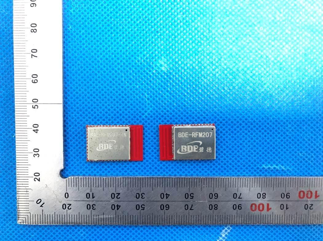
2ABRU-RFM207
May 13, 2021Multiprotocol 2.4G Wireless Module - Industrial Grade
Equipment Class
DTS - Digital Transmission System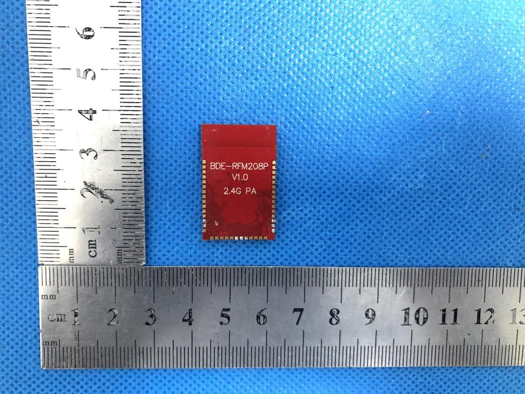
2ABRU-RFM208P24
May 12, 2021Multi-Band Wireless Module with PA
Equipment Class
DTS - Digital Transmission System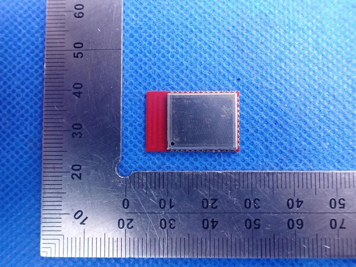
2ABRU-RFM207B
Apr 27, 2021Multiprotocol 2.4G Wireless Module - Industrial Grade
Equipment Class
DTS - Digital Transmission System