2ABSA5011501101
IrriGreen, Inc.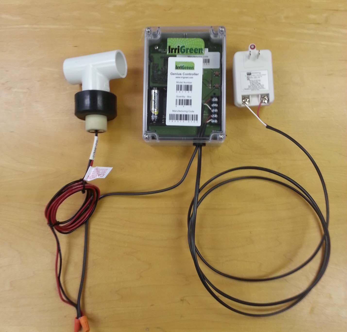
Click to zoom
Application Details
- Equipment Class
- DTS - Digital Transmission System
- Date of Grant
- Aug 09, 2015
- Application Purpose
- Original Equipment
- Date of Application
- Aug 09, 2015
- Equipment Note
- 501101
- Frequency Range
- 2412.00000000 - 2462.00000000
- Company
- IrriGreen, Inc.
- Country
- United States
Documents & Files
Document Text
Text extracted from the exhibit documents filed with the FCC. Open a document above to read the original.
Users Manual
IrriGreen, Inc. 2015 Genius TM Irrigation System Training Manual IrriGreen® manufactures and sells landscape irrigation systems that save water and simplify installation. We use digital technology to water the exact landscape shape cutting installation time in half and reducing wasted water by 50%. IrriGreen contractors generate more profit per installation and greater ownership value to end users. IrriGreen, Inc. 5250 W. 73 rd St., Suite I, Edina, MN 55439 Phone: 612‐238‐7575 www.irrigreen.com IrriGreen Genius Irrigation System – Training Manual Page 1 Changing the way we water the world® TABLE OF CONTENTS Introduction 2 Comparison of the Genius Irrigation System to Conventional Systems 3 Key Features and Benefits of the Genius Irrigation System 4 Selling the Genius Irrigation System 5 Designing & Estimating the Genius Irrigation System 6 Installing the Genius Irrigation System 8 Programming the Genius Irrigation System 12 Replacing the Genius Nozzle and Filter System 19 Warranty 20 Per FCC 15.19 (a) (3) and (a) (4): This device complies with part 15 of the FCC Rules. Operation is subject to the following two conditions: (1) This device may not cause harmful interference, and (2) this device must accept any interference received, including interference that may cause undesired operation. Per FCC 15.21: The user and installer of the IrriGreen Genius Irrigation System shall not make any modifications to the system not expressly approved by IrriGreen. Unauthorized modifications will void the warranty and void the user's authority to operate the equipment per FCC rules. IrriGreen Genius Irrigation System – Training Manual Page 2 Changing the way we water the world® IrriGreen® Genius™ Irrigation System Training Manual Introduction The Genius irrigation system combines digital technology with a patent pending nozzle design to produce an irrigation system capable of distributing water in patterns that fit the shape of the landscape. The Genius irrigation system does this while both reducing the water required to irrigate the landscape and saving significant installation time and materials. The Genius irrigation system is designed to significantly reduce the labor required to install in‐ground irrigation systems while at the same time reducing water required to sufficiently water the lawn. The center of the system is the Genius sprinkler that can be programed to water a wide variety of shapes and sizes. This sprinkler reduces the need for distribution pipe by up to 85%, significantly cuts the number of sprinkler heads required and reduces the amount of water typically wasted to irrigate the lawn by up to 50%. While the cost of the water is born by the property owner, it is still a barrier that can be turned into an opportunity when selling the benefits of Genius irrigation systems to consumers. Reducing installation labor for contractors and reducing end user water bills are compelling reasons for irrigation contractors to sell the Genius irrigation system. You will be able to address business in more price sensitive areas by offering services at a reduced price while maintaining profitability on every installation. Your customers will be happier with green, hassle free lawns and lower water bills than those customers with conventional irrigation systems. This training manual is a component of a training program developed to train experienced irrigation contractors on the techniques unique to installing the Genius irrigation system. This program is intended for licensed (if required by local and/or state code), experienced irrigation contractors for residential and commercial in‐ground irrigation systems. It is not intended as a complete or comprehensive training program for installing in‐ground irrigation systems. THIS TRAINING PROGRAM IS INTENDED FOR IRRIGATION CONTRACTORS THAT ARE ALREADY LICENSED AND/OR EXPERIENCED IRRIGATION PROFESSIONALS. (NOTE: PROFESSIONAL IRRIGATION TRAINING RECOMMENDED.) The following points will be covered by this training program and manual: Comparison of the Genius irrigation system to conventional sprinkler systems. Key features and benefits of the Genius irrigation system. Selling the Genius irrigation system. Installation techniques unique to the Genius irrigation system. Programming the Genius sprinklers. System warranty information. IrriGreen Genius Irrigation System – Training Manual Page 3 Changing the way we water the world® Comparison of the Genius Irrigation System to Conventional Systems 1. System similarities, the Genius irrigation system: Designed to be permanently installed into the landscapes of residential and commercial properties. Designed for use with conventional irrigation controllers, rain sensors, etc. – a hybrid system. Requires the same 24 VAC low voltage power source for Genius Server as conventional controllers. Uses similar distribution pipe and fittings currently being used to install conventional in‐ground irrigation systems, but significantly less pipe length and fewer fittings. Requires the same maintenance for spring start‐up and fall blow‐outs as conventional irrigation systems, and is compatible with regular sequencing for typical blow‐out procedures. Irrigates in watering zones – 1 sprinkler for 1 zone. Works in conjunction with standard industry controllers/schedulers. Uses the same water source as conventional systems. 2. System differences, the Genius irrigation system: Connects off the main line, no need for laterals and valve boxes. Uses software in sprinklers, servers and programmers so the water pattern for each individual Genius sprinkler can be programmed to fit the exact landscape it is watering. Eliminates the need for head‐to‐head watering overlap (see graphics below, Conventional vs. IrriGreen). Genius Sprinklers digitally control the water distance and rotational speed of the multi‐stream nozzle. Uses 12 VDC to power and communicate with each Genius Sprinkler, so distances up to…
Text truncated - open the document above for the full version.
External Photos
IrriGreen Controller Model 501101 External Photos July 20, 2015 View of system similar to test setup Flow Meter 24 VAC Transformer Irrigation Field Wire View of Flow Meter (not made by IrriGreen) 24 VAC transformer (not made by IrriGreen) Front View of IrriGreen Controller Back View of IrriGreen Controller Right View of IrriGreen Controller Left View of IrriGreen Controller Bottom View of IrriGreen Controller Top View of IrriGreen Controller
ID Label/Location Info
IrriGreen Controller Model 501101 Label Photos July 2, 2015 Right View of IrriGreen Controller Label View of IrriGreen Controller
Internal Photos
IrriGreen Controller Model 500101 Internal Photos July 20, 2015 Internal View of IrriGreen Controller and Printed Circuit Board Front Side IrriGreen Controller Printed Circuit Board Back Side 2.4GHzAntenna 433.92 MHz Antenna 3M EMI Absorber IrriGreen Controller Radios Resistor modification for J2 U.FL antenna port 433.92 MHz Radio 2.4 GHz Radio IrriGreen Controller CC1101 433.92 MHz Radio Section IrriGreen Controller CC3100 2.4 GHz Radio Section 2.4 GHz Antenna Port
Operational Description
IrriGreen FCC Antenna Info July 16, 2015 IrriGreen Controller Model 501101 The IrriGreen Controller includes a printed circuit board mounted helical antenna from Linx Technologies, part number ANT‐433‐HETH, for the 433.92 MHz radio. The antenna gain according to the manufacturer is 1.9 dBi. A Texas Instruments CC3100BOOST board is modified for an external 2.4 GHz antenna using a U.FL connector. The Linx antenna part number is ANT‐2.4‐WRT‐UFL. The peak antenna gain according to the manufacturer is 3.5 dBi. The IrriGreen Controller is installed by professional irrigation installers and the circuit board antenna is encased as shown in the external photo exhibits. During testing it was found that an EMI absorber adhered to the Wi‐Fi chip was needed to attenuate spurious transmissions. 433.92 MHz Antenna 2.4 GHz Antenna 3M EMI Absorber
Operational Description
– 1 – Revised 12/9/13 Product Description HE Series antennas are designed for direct PCB mounting. Thanks to the HE’s compact size, they are ideal for internal concealment inside a product’s housing. The HE is also very low in cost, making it well suited to high-volume applications. HE Series antennas have a very narrow bandwidth; thus, care in placement and layout is required. In addition, they are not as efficient as whip-style antennas, so they are generally better suited for use on the transmitter end where attenuation is often required anyway for regulatory compliance. Use on both transmitter and receiver ends is recommended only in instances where a short range (less than 30% of whip style) is acceptable. Features • Very low cost • Compact for physical concealment • Precision-wound coil • Rugged phosphor-bronze construction • Mounts directly to the PCB Electrical Specifications Center Frequency: 433MHz Recom. Freq. Range: 418–458MHz Wavelength: ¼-wave VSWR: ≤ 2.0 typical at center Peak Gain: 1.9dBi Impedance: 50-ohms Connection: Through-hole Oper. Temp. Range: –40°C to +80°C Electrical specifications and plots measured on a 7.62 x 19.05 cm (3.00" x 7.50") reference ground plane ANT-433-HETH Data Sheet by Ordering Information ANT-433-HETH (helical, through-hole) Recommended Mounting 38.10 mm (1.50") 7.62 mm (0.30") 12.70 mm (0.50") 3.81 mm (0.15") No electircal connection on this pad. For physical support only. Ground plane on bottom layer for counterpoise 50-ohm microstrip line No ground plane or traces under the antenna 1.52 mm (Ø0.060") Outside Diameter 8.89 mm (0.35") 6.4 mm (0.25") Inside Diameter 38.1 mm (1.50") 1.3 mm (0.05") Wire Diameter 6.35 mm (0.25") 15.24 mm (0.60") – 2 – by Data Sheet ANT-433-HETH VSWR Graph What is VSWR? The Voltage Standing Wave Ratio (VSWR) is a measurement of how well an antenna is matched to a source impedance, typically 50-ohms. It is calculated by measuring the voltage wave that is headed toward the load versus the voltage wave that is reflected back from the load. A perfect match will have a VSWR of 1:1. The higher the first number, the worse the match, and the more inefficient the system. Since a perfect match cannot ever be obtained, some benchmark for performance needs to be set. In the case of antenna VSWR, this is usually 2:1. At this point, 88.9% of the energy sent to the antenna by the transmitter is radiated into free space and 11.1% is either reflected back into the source or lost as heat on the structure of the antenna. In the other direction, 88.9% of the energy recovered by the antenna is transferred into the receiver. As a side note, since the “:1” is always implied, many data sheets will remove it and just display the first number. How to Read a VSWR Graph VSWR is usually displayed graphically versus frequency. The lowest point on the graph is the antenna’s operational center frequency. In most cases, this will be different than the designed center frequency due to fabrication tolerances. The VSWR at that point denotes how close to 50-ohms the antenna gets. Linx specifies the recommended bandwidth as the range where the typical antenna VSWR is less than 2:1. 159 Ort Lane, Merlin, OR, US 97532 Phone: +1 541 471 6256 Fax: +1 541 471 6251 www.linxtechnologies.com Counterpoise Quarter-wave or monopole antennas require an associated ground plane counterpoise for proper operation. The size and location of the ground plane relative to the antenna will affect the overall performance of the antenna in the final design. When used in conjunction with a ground plane smaller than that used to tune the antenna, the center frequency typically will shift higher in frequency and the bandwidth will decrease. The proximity of other circuit elements and packaging near the antenna will also affect the final performance. For further discussion and guidance on the importance of the ground plane counterpoise, please refer to Linx Application Note AN-00501: Understanding Antenna Specifications and Operation. VSWRReflected Power 3:1 2:1 1:1 25% 11% 0% 433MHz533MHz333MHz 1.438
Operational Description
– 1 – Revised 12/9/13 Product Description The WRT Series antenna is ideally suited for applications such as wireless vending, security, traffic, or power equipment which require an unobtrusive, tamper-resistant antenna solution. The tiny 19 x 11 mm radome installs through a small hole on the product and is anchored by a threaded base. An adhesive foam compression ring is used to resist the elements. The ½-wave antenna also features an integral counterpoise, which eliminates the need for a proximity ground plane. The antenna is suited for mounting in applications where the counterpoise will not be shielded from the antenna (non-conductive or open metal enclosures); installation where the counterpoise is within a shielded enclosure will affect the antenna performance. The antenna’s coax feed is available with SMA, RP-SMA, or a U.FL / MHF compatible connector. U.FL and I-PEX MHF connector standards are compatible with each other. Alternate coax lengths, connectors and custom colors are available for volume OEM customers. Features • Low cost • Unobtrusive • Tamper resistant • Integral counterpoise • Indoor / outdoor • Adhesive or permanent mount Electrical Specifications Center Frequency: 2.45GHz Recom. Freq. Range: 2.4–2.5GHz Wavelength: ½-wave VSWR: ≤ 1.9 typical at center Peak Gain: 3.5dBi Impedance: 50-ohms Connector: RP-SMA, SMA or U.FL / MHF Cable: RG-174, RP-SMA & SMA 1.32 mm U.FL Oper. Temp. Range: –40°C to +90°C Max. Recom. Torque: 4.0 kgf-cm Electrical specifications and plots measured on 10.16 cm x 10.16 cm (4.00" x 4.00”) reference ground plane ANT-2.4-WRT-xxx Data Sheet by Ordering Information ANT-2.4-WRT-RPS (with RP-SMA connector) ANT-2.4-WRT-SMA (with SMA connector) ANT-2.4-WRT-UFL (with U.FL / MHF compatible connector) 19.0 mm (0.75") Cable Length 216.0 mm (8.50") 5.26 mm (0.207") 6.0 mm (0.24") 32.5 mm (1.28") M11x1.0 mm Thread Adhesive Ring Remove protective plastic before installation 11.0 mm (0.43") Counterpoise SMA or RP-SMA U.FLor i-PEX silouette shown in shadow – 2 – VSWRReflected Power 3:1 2:1 1:1 25% 11% 0% 2450MHz2550MHz2350MHz 1.543 by Data Sheet ANT-2.4-WRT-xxx VSWR Graph What is VSWR? The Voltage Standing Wave Ratio (VSWR) is a measurement of how well an antenna is matched to a source impedance, typically 50-ohms. It is calculated by measuring the voltage wave that is headed toward the load versus the voltage wave that is reflected back from the load. A perfect match will have a VSWR of 1:1. The higher the first number, the worse the match, and the more inefficient the system. Since a perfect match cannot ever be obtained, some benchmark for performance needs to be set. In the case of antenna VSWR, this is usually 2:1. At this point, 88.9% of the energy sent to the antenna by the transmitter is radiated into free space and 11.1% is either reflected back into the source or lost as heat on the structure of the antenna. In the other direction, 88.9% of the energy recovered by the antenna is transferred into the receiver. As a side note, since the “:1” is always implied, many data sheets will remove it and just display the first number. How to Read a VSWR Graph VSWR is usually displayed graphically versus frequency. The lowest point on the graph is the antenna’s operational center frequency. In most cases, this will be different than the designed center frequency due to fabrication tolerances. The VSWR at that point denotes how close to 50-ohms the antenna gets. Linx specifies the recommended bandwidth as the range where the typical antenna VSWR is less than 2:1.
RF Exposure Info
This report must not be used to claim product certification, approval, or endorsement by NVLAP, NIST, or any agency of the federal government of the United States of America. This Report may only be duplicated in its entirety IrriGreen, Inc 433.92 MHz Transmitter and Wi-Fi radio FCC 2.1091:2015 Report # IRRI0006.2 NVLAP Lab Code: 200881-0 CERTIFICATE OF EVALUATION 2014-12-10 Product compliance is the responsibility of the client; therefore, the tests and equipment modes of operation represented in this report were agreed upon by the client, prior to testing. The results of this test pertain only to the sample(s) tested. The specific description is noted in each of the individual sections of the test report supporting this certificate of test. This report reflects only those tests from the referenced standards shown in the certificate of test. It does not include inspection or verification of labels, identification, marking or user information. Last Date of Evaluation: July 13, 2015 IrriGreen, Inc Model: 433.92 MHz Transmitter and Wi-Fi radio Radio Equipment Evaluation Standards Specification Method FCC 2.1091:2015 KDB 447498 D01 General RF Exposure Guidance v05r02 Results Method Clause Test Description Applied Results Comments 7.1 Maximum Permissible Exposure Yes Pass Deviations From Standards None Approved By: Don Facteau, IT Manager Report No. IRRI0006.22/9 REVISION HISTORY REV 2014.10.14 Revision Number Description Date Page Number 00 None Report No. IRRI0006.23/9 ACCREDITATIONS AND AUTHORIZATIONS REV 2015.2.19 United States FCC - Designated by the FCC as a Telecommunications Certification Body (TCB). Certification chambers, Open Area Test Sites, and conducted measurement facilities are listed with the FCC. A2LA - Accredited by A2LA to ISO / IEC 17065 as a product certifier. This allows Northwest EMC to certify transmitters to FCC and IC specifications. NVLAP - Each laboratory is accredited by NVLAP to ISO 17025 Canada IC - Recognized by Industry Canada as a Certification Body (CB). Certification chambers and Open Area Test Sites are filed with IC. European Union European Commission – Validated by the European Commission as a Conformity Assessment Body (CAB) under the EMC directive and as a Notified Body under the R&TTE Directive. Australia/New Zealand ACMA - Recognized by ACMA as a CAB for the acceptance of test data. Korea MSIP / RRA - Recognized by KCC’s RRA as a CAB for the acceptance of test data. Japan VCCI - Associate Member of the VCCI. Conducted and radiated measurement facilities are registered. Taiwan BSMI – Recognized by BSMI as a CAB for the acceptance of test data. NCC - Recognized by NCC as a CAB for the acceptance of test data. Singapore IDA – Recognized by IDA as a CAB for the acceptance of test data. Israel MOC – Recognized by MOC as a CAB for the acceptance of test data. Hong Kong OFCA – Recognized by OFCA as a CAB for the acceptance of test data. Vietnam MIC – Recognized by MIC as a CAB for the acceptance of test data. SCOPE For details on the Scopes of our Accreditations, please visit: http://www.nwemc.com/accreditations/ http://gsi.nist.gov/global/docs/cabs/designations.html Report No. IRRI0006.24/9 FACILITIES REV 2015.2.19 California Labs OC01-13 41 Tesla Irvine, CA 92618 (949) 861-8918 Minnesota Labs MN01-08, MN10 9349 W Broadway Ave. Brooklyn Park, MN 55445 (612)-638-5136 New York Labs NY01-04 4939 Jordan Rd. Elbridge, NY 13060 (315) 554-8214 Oregon Labs EV01-12 22975 NW Evergreen Pkwy Hillsboro, OR 97124 (503) 844-4066 Texas Labs TX01-09 3801 E Plano Pkwy Plano, TX 75074 (469) 304-5255 Washington Labs NC01-05 19201 120 th Ave NE Bothell, WA 9801 (425)984-6600 NVLAP NVLAP Lab Code: 200676-0 NVLAP Lab Code: 200881-0 NVLAP Lab Code: 200761-0 NVLAP Lab Code: 200630-0 NVLAP Lab Code:201049-0 NVLAP Lab Code: 200629-0 Industry Canada 2834B-1, 2834B-3 2834E-1 N/A 2834D-1, 2834D-2 2834G-1 2834F-1 BSMI SL2-IN-E-1154R SL2-IN-E-1152R N/A SL2-IN-E-1017 SL2-IN-E-1158R SL2-IN-E-1153R VCCI A-0029 A-0109 N/A A-0108 A-0201 A-0110 Recognized Phase I CAB for ACMA, BSMI, IDA, KCC/RRA, MIC, MOC, NCC, OFCA US0158 US0175 N/A US0017 US0191 US0157 Report No. IRRI0006.25/9 PRODUCT DESCRIPTION 2014-12-10 Client and Equipment Under Test (EUT) Information Company Name: IrriGreen, Inc Address: 5250 West 73rd Street, Suite I City, State, Zip: Edina, MN 55439 Test Requested By: Gary Klinefelter Model: 433.92 MHz Transmitter and Wifi radio Evaluation Date: July 13, 2015 Information Provided by the Party Requesting the Test Functional Description of the EUT: IrriGreen has developed a new box to add to their irrigation system. This box has a 433MHz radio that talks to their IrriGreen Server and also a TI CC3100 WiFi module to talk to a phone. It also has a connection for a flow sensor and a 24 VAC transformer. The antennas are used greater than 20 cm away from the user, and the radios cannot transmit simultaneously. Therefore a standalone MPE evaluation is applicable. Evaluation Objective: To demonstrate compliance with FCC requirements for RF exposure for 2.1091 mobile devices. Report No. IRRI0006.26/9 MAXIMUM PERMISSIBLE EXPOSURE (MPE) WTD.2014.12.17 OVERVIEW Human exposure to RF emissions from mobile devices (47 CFR §2.1091) may be evaluated based on the MPE limits adopted by the FCC for electric and magnetic field strength and/or power density, as appropriate, since exposures are assumed to occur at distances of 20 cm or more from persons. ANSI C95.1:2005 + Amd 1:2010 specifies a minimum separation distance of 20 cm for performing reliable field measurements to determine adherence to MPE limits. If the minimum separation distance between a transmitter and nearby persons is more than 20 cm under normal operating conditions, compliance with MPE limits may be determined at such distance from the transmitter. When applicable, operation instructions and prominent warning labels may be used to alert the exposed persons to maintain a specified distance from the transmitter or to limit their exposu…
Text truncated - open the document above for the full version.
Test Report
This report must not be used to claim product certification, approval, or endorsement by NVLAP, NIST, or any agency of the federal government of the United States of America. This Report may only be duplicated in its entirety IrriGreen, Inc. 501101 FCC 15.207:2015 FCC 15.247:2015 Report # IRRI0007 NVLAP Lab Code: 200881-0 CERTIFICATE OF TEST 2014-12-10 Product compliance is the responsibility of the client; therefore, the tests and equipment modes of operation represented in this report were agreed upon by the client, prior to testing. The results of this test pertain only to the sample(s) tested. The specific description is noted in each of the individual sections of the test report supporting this certificate of test. This report reflects only those tests from the referenced standards shown in the certificate of test. It does not include inspection or verification of labels, identification, marking or user information. Last Date of Test: July 09, 2015 IrriGreen, Inc. Model: 501101 Radio Equipment Testing Standards Specification Method FCC 15.207:2015 ANSI C63.10:2009 FCC 15.247:2015 ANSI C63.10:2009 Results Method Clause Test Description Applied Results Comments 6.2 AC Powerline Conducted Emissions Yes Pass 6.5, 6.6 Spurious Radiated Emissions Yes Pass 6.7 Spurious Conducted Emissions Yes Pass 6.7 Band Edge Compliance Yes Pass 6.9.1 Occupied Bandwidth Yes Pass 6.10.2 Output Power Yes Pass 6.11.2 Power Spectral Density Yes Pass 7.5 Duty Cycle Yes N/A Characterization of test software operation. Deviations From Test Standards None Approved By: Tim O'Shea, Operations Manager Report No. IRRI00072/130 REVISION HISTORY REV 2014.10.14 Revision Number Description Date Page Number 00 None Report No. IRRI00073/130 ACCREDITATIONS AND AUTHORIZATIONS REV 2015.2.19 United States FCC - Designated by the FCC as a Telecommunications Certification Body (TCB). Certification chambers, Open Area Test Sites, and conducted measurement facilities are listed with the FCC. A2LA - Accredited by A2LA to ISO / IEC 17065 as a product certifier. This allows Northwest EMC to certify transmitters to FCC and IC specifications. NVLAP - Each laboratory is accredited by NVLAP to ISO 17025 Canada IC - Recognized by Industry Canada as a Certification Body (CB). Certification chambers and Open Area Test Sites are filed with IC. European Union European Commission – Validated by the European Commission as a Conformity Assessment Body (CAB) under the EMC directive and as a Notified Body under the R&TTE Directive. Australia/New Zealand ACMA - Recognized by ACMA as a CAB for the acceptance of test data. Korea MSIP / RRA - Recognized by KCC’s RRA as a CAB for the acceptance of test data. Japan VCCI - Associate Member of the VCCI. Conducted and radiated measurement facilities are registered. Taiwan BSMI – Recognized by BSMI as a CAB for the acceptance of test data. NCC - Recognized by NCC as a CAB for the acceptance of test data. Singapore IDA – Recognized by IDA as a CAB for the acceptance of test data. Israel MOC – Recognized by MOC as a CAB for the acceptance of test data. Hong Kong OFCA – Recognized by OFCA as a CAB for the acceptance of test data. Vietnam MIC – Recognized by MIC as a CAB for the acceptance of test data. SCOPE For details on the Scopes of our Accreditations, please visit: http://www.nwemc.com/accreditations/ http://gsi.nist.gov/global/docs/cabs/designations.html Report No. IRRI00074/130 MEASUREMENT UNCERTAINTY TMU.2015.07.10 Measurement Uncertainty When a measurement is made, the result will be different from the true or theoretically correct value. The difference is the result of tolerances in the measurement system that cannot be completely eliminated. To the extent that technology allows us, it has been our aim to minimize this error. Measurement uncertainty is a statistical expression of measurement error qualified by a probability distribution. A measurement uncertainty estimation has been performed for each test per our internal quality document WP 342. The estimation is used to compare the measured result with its "true" or theoretically correct value. The expanded measurement uncertainty (K=2) for each test is on each data sheet. Our measurement data meets or exceeds the measurement uncertainty requirements of the applicable specification; therefore, the test data can be compared directly to the specification limit to determine compliance. The calculations for estimating measurement uncertainty are based upon ETSI TR 100 028 (or CISPR 16-4-2 as applicable), and are available upon request. The following table represents the Measurement Uncertainty (MU) budgets for each of the tests that may be contained in this report. Test + MU - MU Frequency Accuracy (Hz) 0.0007% -0.0007% Amplitude Accuracy (dB) 1.2 dB -1.2 dB Conducted Power (dB) 0.3 dB -0.3 dB Radiated Power via Substitution (dB) 0.7 dB -0.7 dB Temperature (degrees C) 0.7°C -0.7°C Humidity (% RH) 2.5% RH -2.5% RH Voltage (AC) 1.0% -1.0% Voltage (DC) 0.7% -0.7% Field Strength (dB) 5.2 dB -5.2 dB AC Powerline Conducted Emissions (dB) 2.4 dB -2.4 dB Report No. IRRI00075/130 FACILITIES REV 2015.2.19 California Labs OC01-13 41 Tesla Irvine, CA 92618 (949) 861-8918 Minnesota Labs MN01-08, MN10 9349 W Broadway Ave. Brooklyn Park, MN 55445 (612)-638-5136 New York Labs NY01-04 4939 Jordan Rd. Elbridge, NY 13060 (315) 554-8214 Oregon Labs EV01-12 22975 NW Evergreen Pkwy Hillsboro, OR 97124 (503) 844-4066 Texas Labs TX01-09 3801 E Plano Pkwy Plano, TX 75074 (469) 304-5255 Washington Labs NC01-05 19201 120 th Ave NE Bothell, WA 9801 (425)984-6600 NVLAP NVLAP Lab Code: 200676-0 NVLAP Lab Code: 200881-0 NVLAP Lab Code: 200761-0 NVLAP Lab Code: 200630-0 NVLAP Lab Code:201049-0 NVLAP Lab Code: 200629-0 Industry Canada 2834B-1, 2834B-3 2834E-1 N/A 2834D-1, 2834D-2 2834G-1 2834F-1 BSMI SL2-IN-E-1154R SL2-IN-E-1152R N/A SL2-IN-E-1017 SL2-IN-E-1158R SL2-IN-E-1153R VCCI A-0029 A-0109 N/A A-0108 A-0201 A-0110 Recognized Phase I CAB for ACMA, BSMI, IDA, KCC/RRA, MIC, MOC, …
Text truncated - open the document above for the full version.
Test Report
This report must not be used to claim product certification, approval, or endorsement by NVLAP, NIST, or any agency of the federal government of the United States of America. This Report may only be duplicated in its entirety IrriGreen, Inc IrriGreen Genius System - Controller FCC 15.207:2015 FCC 15.231:2015 Report # IRRI0006 NVLAP Lab Code: 200881-0 CERTIFICATE OF TEST 2014-12-10 Product compliance is the responsibility of the client; therefore, the tests and equipment modes of operation represented in this report were agreed upon by the client, prior to testing. The results of this test pertain only to the sample(s) tested. The specific description is noted in each of the individual sections of the test report supporting this certificate of test. This report reflects only those tests from the referenced standards shown in the certificate of test. It does not include inspection or verification of labels, identification, marking or user information. Last Date of Test: June 16, 2015 IrriGreen, Inc Model: IrriGreen Genius System - Controller Radio Equipment Testing Standards Specification Method FCC 15.207:2015 ANSI C63.10:2009 FCC 15.231:2015 ANSI C63.10:2009 Results Method Clause Test Description Applied Results Comments 6.2 Powerline Conducted Emissions Yes Pass 6.5, 6.6 Spurious Radiated Emissions Yes Pass 6.5, 6.6 Field Strength of Fundamental Yes Pass 6.9.1 Occupied Bandwidth Yes Pass 7.5 Duty Cycle Yes Pass Deviations From Test Standards None Approved By: Tim O'Shea, Operations Manager Report No. IRRI00062/32 REVISION HISTORY REV 2014.10.14 Revision Number Description Date Page Number 00 None Report No. IRRI00063/32 ACCREDITATIONS AND AUTHORIZATIONS REV 2015.2.19 United States FCC - Designated by the FCC as a Telecommunications Certification Body (TCB). Certification chambers, Open Area Test Sites, and conducted measurement facilities are listed with the FCC. A2LA - Accredited by A2LA to ISO / IEC 17065 as a product certifier. This allows Northwest EMC to certify transmitters to FCC and IC specifications. NVLAP - Each laboratory is accredited by NVLAP to ISO 17025 Canada IC - Recognized by Industry Canada as a Certification Body (CB). Certification chambers and Open Area Test Sites are filed with IC. European Union European Commission – Validated by the European Commission as a Conformity Assessment Body (CAB) under the EMC directive and as a Notified Body under the R&TTE Directive. Australia/New Zealand ACMA - Recognized by ACMA as a…
Text truncated - open the document above for the full version.
Contact Information
Applicant
Gary M Klinefelter(CEO)
Test Firm
Northwest EMC, Inc.Greg Kiemel
Technical Specifications
| # | Rule Parts | Frequency Range | Power Output |
|---|---|---|---|
| 1 | 15C | 2.41 GHz - 2.46 GHz | 51.00 mW |
Other Applications from IrriGreen, Inc.
2ABSA7051
Sep 22, 2024705101
Equipment Class
DTS - Digital Transmission System
2ABSA5001
Mar 16, 2014500101
Equipment Class
DSC - Part 15 Security/Remote Control Transmitter