2ABTR-NTM-MCP04TC01Perception Neuron Studio
Beijing Noitom Technology Ltd.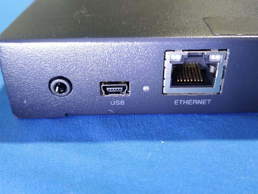
Click to zoom
Application Details
- Equipment Class
- DXX - Part 15 Low Power Communication Device Transmitter
- Date of Grant
- Jan 01, 2020
- Application Purpose
- Original Equipment
- Date of Application
- Jan 01, 2020
- Equipment Note
- Perception Neuron Studio
- Frequency Range
- 2402.00000000 - 2482.00000000
- Country
- China
Documents & Files
Document Text
Text extracted from the exhibit documents filed with the FCC. Open a document above to read the original.
Users Manual
AXIS STUDIO USER GUIDE Ver 1.1.9931.181 Perception Neuron Studio DISCLAIMER The information in this document is subject to change without notice and does not represent a commitment on the part of NOITOM . The software described by this document is subject to a License Agreement and may not be copied to other media. No part of this publication may be copied, reproduced or otherwise transmitted or recorded, for any purpose,without prior written permission by NOITOM, hereinafter referred to as NOITOM “AXIS STUDIO” and “PERCEPTION NEURON” are registered trademarks of NOITOM Ltd Table of Contents 1. Software Installation ����������������������������������1 2. Hardware Preparation ���������������������������������2 3. Getting Started with Axis Studio ���������������������������8 4. Window Layout overview - Capture View ���������������������11 5. Window Layout overview - Edit View ������������������������17 6. Window Layout overview - Project Management ������������������20 7. Window Layout overview - Menu ��������������������������22 8. Troubleshooting �����������������������������������27 1AXIS STUDIO USER GUIDE SystemMicrosoft Windows 10 RAM4 GB and above Display adapters Nvidia or AMD VRAM 2GB and above Support for OpenGL 4.4 and above Support Directx9 and above Other requirements Two standard USB ports one Ethernet port 1.2. Software Installation 1. Download Axis_Studio_x64.msi 2. Open the file and follow the instructions in the setup wizard. 1.1. System Requirements 1. Software Installation AXIS STUDIO USER GUIDE2 2. Hardware Preparation 2.1. Equipment Checklist PN Studio sensor Wireless MEMS inertial sensor. Gyroscope, accelerometer and magnetometer integrated. PN Studio Transceiver All sensor data will broadcast to the transceiver wirelessly by 2.4GHz. The antenna is linked to the transceiver to enhance the power. Charging Case Case for charging and storing sensors. Body Straps 14 set of straps to mount Perception Neuron Studio sensors around your body. 2.2. Charging Sensors 1. Place sensors into the charging case 2. Close the charging case cover 3. Connect the adapter with the power cord to the charging case. 3AXIS STUDIO USER GUIDE 2.3. Wearing Sensors 1. Use the appropriate length of strap that fits the performer for each segment. Attach the straps according to the diagram below. AXIS STUDIO USER GUIDE4 2. Place the sensors into the bases. Rotate the sensors 90 degrees clockwise. 2.4. Transceiver Setup Tip: USB mode can be used when one transceiver and one PN STUDIO is in operation. USB connection When attaching the Transceiver to the computer for the first time, the IP address for the TRANSCEIVER Remote Network Driver Interface ( RNDIS ) needs to be configured. 1. Connect the USB to the Transceiver 2. Connect the USB to the Computer 3. Open Network Connections: Control Panel Network and Internet Network and Sharing Center Change Adapter Settings 5AXIS STUDIO USER GUIDE 4. In the Network Connections panel, locate an adapter with Remote NDIS properties. This new adapter detected by your computer is your Perception Neuron Studio Transceiver. AXIS STUDIO USER GUIDE6 5. Open the properties of the Remote NDIS, and open the IPV4 settings. 6. Set the following IPV4 properties: IP Address: 192.168.1.200* ( range: 192.168.1-192.168.1.240 ) Subnet Mask: 255.255.255.0 7. Confirm settings and exit all Network Property windows. 8. Restart Transceiver by disconnecting and reconnecting USB cable from the Transceiver. 9. Open Axis Studio software* * If 192.168.1.200 is taken by an existing Network Adapter then choose one from the provided IP range. Network Adapters cannot have conflicting IP addresses. *If the transceiver is not shown in the software, please check USB transceiver link troubleshooting Ethernet Connection If you are using two or more transceivers simultaneously, use an unmanaged switch and a DHCP enabled router to synchronize the transceivers data. 1. Connect an Ethernet cable from the PC to the router. 2. Connect an Ethernet cable from the router to the switch. 3. Connect Ethernet cables from the transceivers to the switch. 4. Once the transceivers have been connected successfully they show now appear in the software. 7AXIS STUDIO USER GUIDE 2.5. Working Environment Perception Neuron Studio inertial system contains magnetometers, magnetometer sensors can be affected by strong magnetic environment. Users must operate the sensors in an environment with the least amount of magnetic interference. If you choose to use Perception Neuron Studio Inertial System in a location with strong magnetic interference, utilize our “Anti-mag mode” found in our software. 10-100 cm Keep 10-100 cm (depending on the strength of the source) away from magnetic sources. Permanent Magnet Power box Computer / keyboard / mouse Generator / Electric motor Speaker Television Headphone Refrigerator AXIS STUDIO USER GUIDE8 3.1. Open Axis Studio Open Axis Studio from the desktop shortcut 3.2. Create Project Use Projects to manage all the files associated with motion capture sessions. · Click New Project · Enter the project name and choose the location of the project. · Selecting Add default body size will include body size presets into your project. 3. Getting Started with Axis Studio 3.3. Measure Body Segment Length Axis Studio allows users to input their own body size dimensions if the provided default body size presets do not apply. Prior to capturing, choose the body size preset that fits the actor‘s body dimension closest before carrying out the posture calibration. Inertial motion capture accuracy is highly affected by the body segment length of the Avatar. 9AXIS STUDIO USER GUIDE 3.4. Link Inertial Sensors to Axis Studio Turn sensors and gloves on, click the “Connect” button , then check the sensor map panel for status. In the avatar diagram, green indicators confirm sensors are connected. 3.5. Check Sensor Magnetic Status Check the magnetic status in the sensor map panel, green indicators confirm sensors are i…
Text truncated - open the document above for the full version.
Cover Letter(s)
QA-FR-170-B 7/29/2014 Company: Beijing Noitom Technology Ltd. Add: 502,Tower A,28 Xinjiekouwai Blvd, Beijing,China Tel: 010-82055391 Email: [email protected] FCC Authorization 2019-12-27 FEDERAL COMMUNICATIONS COMMISSIONS Authorization and Evaluation Division 7435 Oakland Mills Road Columbia, MD 21046 Subject: Agent Authorization To whom it may concern: We Beijing Noitom Technology Ltd., Hereby authorizes Bay Area Compliance Laboratory Corp. to act on its behalf in all matters relating to application for Equipment authorization, including the signing of all documents relating to these matters. All acts carried out by Bay Area Compliance Laboratory Corp. on our behalf shall have the same effect as our own action. We, the undersigned, hereby certify that we are not subject to a denial of federal benefits, that includes FCC benefits, pursuant to Section 5301 of the Anti-Drug Abuse Act of 1988, 21 U.S.C. 862. This authorization is valid until further written notice from the applicant. Sincerely Yours, Signature: Printed Name: Wuda Liu Title: Manager
Cover Letter(s)
QA-FR-171-A Company: Beijing Noitom Technology Ltd. Add: 502,Tower A,28 Xinjiekouwai Blvd, Beijing,China Tel: 010-82055391 Email: [email protected] FCC Confidential Authorization Date:2019-12-27 FEDERAL COMMUNICATIONS COMMISSIONS Authorization and Evaluation Division 7435 Oakland Mills Road Columbia, MD 21046 Subject: Confidentiality Request regarding application for certification of FCC ID: 2ABTR-NTM-MCP04TC01 In accordance with Sections 0.457 and 0.459 of the Commission’s Rules, Beijing Noitom Technology Ltd. hereby requests long-term confidential treatment of information accompanying this application as outlined below: Block Diagram Schematics Operation Description The above materials contain proprietary and confidential information not customarily released to the public. The public disclosure of these materials provides unjustified benefits to its competitors in the market. Sincerely, Signature: Printed Name: Wuda Liu Title: Manager
External Photos
EXHIBIT B - EUT EXTERNAL PHOTOGRAPHS
ID Label/Location Info
Label Label Location Label here
Internal Photos
EXHIBIT C - EUT INTERNAL PHOTOGRAPHS Uncover RF Chip
Test Report
FCC PART 15.249 TEST REPORT For Beijing Noitom Technology Ltd. 502,Tower A,28 Xinjiekouwai Blvd, Beijing,China FCC ID: 2ABTR-NTM-MCP04TC01 Report Type: Original Report Product Name: Perception Neuron Studio Re port Number: RBJ191126052-00 Re port Date: 2019-12-27 Reviewed By: Jerry Zhang EMC Manager Test Laboratory: Bay Area Compliance Laboratories Corp. (Dongguan) No.69 Pulongcun, Puxinhu Industry Area, Tangxia, Dongguan, Guangdong, China Tel: +86-769-86858888 Fax: +86-769-86858891 www.baclcorp.com.cn Bay Area Compliance Laboratories Corp. (Dongguan) Report No.: RBJ191126052-00 Page 2 of 27 TABLE OF CONTENTS GENERAL INFORMATION ....................................................................................................................................... 3 PRODUCT DESCRIPTION FOR EQUIPMENT UNDER TEST (EUT) ..................................................................................... 3 OBJECTIVE ................................................................................................................................................................... 3 RELATED SUBMITTAL(S)/GRANT(S) ............................................................................................................................. 3 TEST METHODOLOGY .................................................................................................................................................. 3 MEASUREMENT UNCERTAINTY .................................................................................................................................... 4 TEST FACILITY ............................................................................................................................................................. 4 DECLARATIONS ............................................................................................................................................................ 4 SYSTEM TEST CONFIGURATION .......................................................................................................................... 5 JUSTIFICATION ............................................................................................................................................................. 5 EUT EXERCISE SOFTWARE .......................................................................................................................................... 5 EQUIPMENT MODIFICATIONS ....................................................................................................................................... 5 LOCAL SUPPORT EQUIPMENT LIST AND DETAILS ........................................................................................................ 5 SUPPORT CABLE LIST AND DETAILS ............................................................................................................................ 5 BLOCK DIAGRAM OF TEST SETUP ................................................................................................................................ 6 SUMMARY OF TEST RESULTS ............................................................................................................................... 7 FCC§15.203 - ANTENNA REQUIREMENT .............................................................................................................. 8 APPLICABLE STANDARD .............................................................................................................................................. 8 ANTENNA CONNECTOR CONSTRUCTION ...................................................................................................................... 8 FCC §15.207 (A)– AC LINE CONDUCTED EMISSIONS ....................................................................................... 9 APPLICABLE STANDARD .............................................................................................................................................. 9 EUT SETUP .................................................................................................................................................................. 9 EMI TEST RECEIVER SETUP ......................................................................................................................................... 9 TEST PROCEDURE ...................................................................................................................................................... 10 CORRECTED AMPLITUDE & MARGIN CALCULATION ................................................................................................. 10 TEST EQUIPMENT LIST AND DETAILS ......................................................................................................................... 10 TEST DATA ................................................................................................................................................................ 11 FCC§15.205, §15.209&§15.249- RADIATED EMISSIONS .................................................................................... 15 APPLICABLE STANDARD ............................................................................................................................................ 15 EUT SETUP ................................................................................................................................................................ 15 TEST EQUIPMENT SETUP ............................................................................................................................................ 16 TEST PROCEDURE ...................................................................................................................................................... 17 CORRECTED AMPLITUDE & MARGIN CALCULATION ................................................................................................. 17 TEST EQUIPMENT LIST AND DETAILS ......................................................................................…
Text truncated - open the document above for the full version.
Test Setup Photos
EXHIBIT D - TEST SETUP PHOTOGRAPHS Conducted Emissions Front View M1 Conducted Emissions Side View M1 Conducted Emissions Front View M2 Conducted Emissions Side View M2 Radiated Emission Below 1GHz View M1 Radiated Emission Below 1GHz View M2 Radiated Emission Above 1GHz View
Contact Information
Applicant
Wuda Liu(Manager)
Test Firm
Bay Area Compliance Laboratories Corp.(Dongguan)David Zhang
[email protected]0086 0769 86858888
Technical Specifications
| # | Rule Parts | Frequency Range | Power Output |
|---|---|---|---|
| 1 | 15C | 2.40 GHz - 2.48 GHz | - |
Other Applications from Beijing Noitom Technology Ltd.
2ABTR-NTM-MCP05BS01
Jul 19, 2021Perception Neuron 3
Equipment Class
DXX - Part 15 Low Power Communication Device Transmitter
2ABTR-NTM-MCP05TC01
Apr 22, 2021Perception Neuron 3
Equipment Class
DTS - Digital Transmission System
2ABTR-E01-NYT-02
Mar 18, 2020Perception Neuron Studio
Equipment Class
DXX - Part 15 Low Power Communication Device Transmitter
2ABTRRECEIVER
Oct 12, 2014PERCEPTION Receiver
Equipment Class
DXX - Part 15 Low Power Communication Device Transmitter
2ABTRTRACKER
Sep 22, 2014PERCEPTION Tracker
Equipment Class
DXX - Part 15 Low Power Communication Device Transmitter