2ABTU-PM-522TABLET PC
RuggON Corporation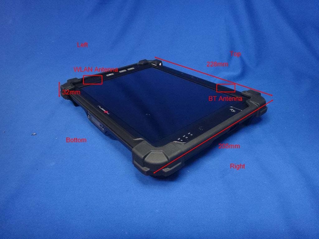
Click to zoom
Application Details
- Equipment Class
- DXX - Part 15 Low Power Communication Device Transmitter
- Date of Grant
- Aug 21, 2014
- Application Purpose
- Original Equipment
- Date of Application
- Aug 19, 2014
- Equipment Note
- TABLET PC
- Frequency Range
- 13.56000000 - 13.56000000
- Company
- RuggON Corporation
- Country
- Taiwan
Documents & Files
Document Text
Text extracted from the exhibit documents filed with the FCC. Open a document above to read the original.
Users Manual
PM-522 User's Manual ©2014 RuggON Corporation. All rights reserved. TRADEMARKS RuggON logo is a trademark of RuggON Corporation, registered in the United States Patent and Trademark Office and in other countries. Microsoft and the Windows logo are either registered trademarks or trademarks of Microsoft Corporation in the United States and/or other countries. Microsoft products are licensed to OEMs by Microsoft Licensing, Inc., a wholly owned subsidiary of Microsoft Corporation. The Bluetooth® word mark and logos are registered trademarks owned by Bluetooth SIG, Inc. All other brand and product names are trademarks or registered trademarks of their respective owners. Images shown in this document may vary slightly from actual products at time of shipping. Information in this manual is subject to change without notice. Table of Contents About This Manual Related Information ......................................................................................1 Conventions..................................................................................................1 Basic Safety Guidelines Maintenance and Operation Overview .........................................................2 Safety ...........................................................................................................2 Intended Use ................................................................................................2 Electrical Hazards.........................................................................................2 Safety Guidelines for Mounting ....................................................................3 Radio Transmissions ....................................................................................4 Cleaning and Servicing.................................................................................4 Regulatory and Certification .........................................................................5 Lithium Battery Safety Statement .................................................................6 Chapter 1. Introduction About This Guide ..........................................................................................7 Unpacking the Device...................................................................................7 Parts List.......................................................................................................8 Technical Specifications ...............................................................................9 Identifying the Device .................................................................................11 Dimensions .................................................................................................15 Touch Screen..............................................................................................16 Chapter 2. Getting Started PM-522 Configuration Options ...................................................................17 Installing the Bumpers ................................................................................18 Removing the I/O Cover .............................................................................20 Replacing the I/O Cover .............................................................................21 Connecting to External Cabling ..................................................................22 Charging the Battery...................................................................................30 1 Chapter 3. Operation Before First Time Use .................................................................................33 Powering Up and Down the Device ............................................................34 Connecting to Network ...............................................................................35 Calibrating the Touch Screen .....................................................................35 Using the CMOS Setup Utility ....................................................................36 Chapter 4. Troubleshooting Troubleshoot the Wi-Fi Connection ............................................................38 Troubleshoot 802.1x Security .....................................................................39 Check 802.11 Network Status ....................................................................39 Troubleshoot Reading Bar Codes ..............................................................40 Troubleshoot Operating the Computer .......................................................42 Call Product Support ..................................................................................42 Restart Your Computer ...............................................................................43 Chapter 5. Maintenance Cleaning the Device ...................................................................................43 Returning the Device ..................................................................................43 Contacting RuggON ...................................................................................43 ii 1 About This Manual The PM-522 User’s Manual provides instruction for qualified personnel to follow when setting up a new PM-522 device. This document is intended for use by qualified personnel to compliment the training and expertise, not to replace it. Related Information Current information and manuals are available for download at the following website: http://www.ruggon.com Conventions Bolded or underlined text is used to emphasize the designated information. A Note is used to provide additional information for the device or settings. A Caution is used to warn against potential hazards or to caution against unsafe practices. A Warning is used to identify immediate hazards for property damage, injury or death. Basic Safety Guidelines The following safety guidelines are intended to help protect the user from injury and prevent damage to the hardware. „ Do not place anything on the AC adapters power cable…
Text truncated - open the document above for the full version.
Users Manual
Connecting to External Cabling To prevent damage to the device, connect all cabling and accessories before powering up the device. Connect USB Cabling The PM-522 have two USB ports for connecting USB devices, such as a digital camera, scanner, printer, modem, and mouse. The USB ports support USB 2.0 or USB 3.0 devices. 1. Open the I/O cover. See “Removing the I/O Cover” on page 22. 2. Connect to USB device via USB cable. Figure 23. Connect USB Cabling Connect Ethernet Cabling The PM-522 provide mini USB to RJ45 dougle for connecting Ethernet. Use a shielded cable is required to maintain emissions and susceptibility compliance. 1. Open the I/O cover. See “Removing the I/O Cover” on page 22. 2. Connect the mini USB to RJ45 dongle to micro USB port on the PM-522. 3. Connect LAN cable to mini USB to RJ45 dongle. Figure 24. Connect Mini USB to RJ45 Dongle Connect Audio Cabling For higher audio quality, you can send sound through external audio devices such as speakers, headphones, or earphone using audio connector. 1. Open the I/O cover. See “Removing the I/O Cover” on page 22. 2. Connect the audio cable. Figure 25. Connect Audio Cabling Handstrap and Shoulder Strap The PM-522 is equipped with a handstrap and a shoulder strap to provide users safety use. For more information, see “Find Your Configuration Number” on page 62 and “Connecting the Shoulder Strap” on page 29. Connecting the Handstrap 1. Remove the screws securing the bumpers. Figure 26. Removing the Screws 2. Install the D-rings. Make sure the D-rings are tightly secured before installing the handstrap. Figure 27. Installing the D-rings 4. Connect to lock the handstrap on the D-rings. 24 Getting Started When handstrap is installed, the stylus can place with handstrap. Figure 28. Connecting the Handstrap 25 Getting Started Removing the Handstrap 1. Unlock the handstrap from the D-rings. Figure 29. Removing the Handstrap 2. Remove the D-rings. Figure 30. Removing the D-rings 26
Users Manual
Getting Started 3. Secure the bumper and the PM-522 with screws. Figure 31. Sevuring the Screws Connecting the Shoulder Strap 1. Remove the screws securing the bumpers. Figure 32. Removing the Screws 27 Getting Started 2. Install the D-rings. Make sure the D-rings are tightly secured before attaching the shoulder strap. Figure 33. Installing the D-rings 3. Attach the clips to the D-rings to attach the shoulder strap. Figure 34. Connecting the Shoulder Strap 28 Getting Started Removing the Shoulder Strap 1. Press in the clips to release them from the D-rings. 2. Remove the clips. Figure 35. Removing the Shoulder Strap 3. Remove the D-rings. Figure 36. Removing the D-rings 29 Getting Started 4. Secure the bumper and the PM-522 with screws. Figure 37. Sevuring the Screws Charging the Battery When you use the AC adapter to connect your PM-522 to a power outlet, the internal battery will automatically begin to recharge. While the battery is charging, the Power LED will be active. When the battery is fully charged, the Power LED is lit a solid green. 1. Flip open the DC-IN cover to expose the DC-IN jack. Figure 38. Opening the DC-IN Cover 30 Getting Started 2. Connect the AC adapter to the DC-IN port. Figure 39. Connecting the AC Adapter 3. Tap the battery icon on the right bottom side of Windows 8 screen. Check to see if the charging process is active. Figure 40. Battery Information After charging the battery, disconnect the AC adapter and close the DC-IN cover. 1. Align the plastic tab on the DC-IN cover with the compartment. Figure 41. Align the DC-IN Cover 2. Insert one end of the cover first and angle the cover to seat it in place. 31
Users Manual
Getting Started 3. Push in the cover to seal the DC-IN compartment. Figure 42. Installing the DC-IN Cover The DC-IN cover must be inserted correctly to prevent internal damage to the device. Removing the Protective Film from the Display The front display of the PM-522 is protected during transport by a transparent film. This film should remain on the front display during assembly to avoid damage to the front display surface. Only remove the film once all of the assembly work has been completed. 32 Chapter 3. Operation Before First Time Use 1. Flip up the external battery cover with an angle. Figure 95. Removing the External Battery Cover Operation 2. Use a tool to switch the DIP switch to ON. Figure 96. Switching the DIP Switch ON OFF 33 Operation 3. Install the external battery cover to the battery cover holder. Figure 97. Installing the External Battery Cover Powering Up and Down the Device Powering Up the Device Only power up the PM-522 after connecting all of the devices. 1. Press and hold the power switch for 2 seconds. Figure 98. Power Up the PM-522 Powering Down the Device 1. Press and hold the power switch for 5 seconds. Figure 99. Power Down the PM-522 34 Connecting to Network PM-522 Supports two ways to connect to a network: LAN and Wireless LAN Wireless Calibrating the Touch Screen The touch screens of all PM-522 devices that come delivered with an operating system (Windows or Linux) are already calibrated. You may need to calibrate your screen if you tap on one area and it registers in a different area of the screen. Make sure you use the stylus to complete the alignment process. 1. Tap Start > All Programs > HIDeGalaxTouch Tool > HIDeGalaxTouch Tool. The HIDeGalaxTouch Tool appear. Figure 100. HIDeGalaxTouch Tool 2. Tap 4 Points Calibration, 9 Points Linearization or 25 Points Linearization. Figure 101. Calibration Screen 35 Operation 3. Tap and hold until shows OK. Figure 102. Calibration Screen 4. Tap OK to complete calibrate. Figure 103. Complete Calibrate Using the CMOS Setup Utility Your ruggedized tablet has a CMOS setup utility which allows you to configure important system settings, including settings for the Boot and AP menus. This chapter explains how to use the CMOS Setup Utility. BIOS Setup Menu The CMOS Setup Utility allows you to configure your device’s basic settings. When you turn your device on, the system reads this information to initialize the hardware so that it can operate correctly. You can use the setup utility to change your device’s start-up configuration. Starting the CMOS Setup Utility The CMOS Setup Utility is only accessible during boot-up of the device and before the Windows interface appears. If the device is already on, shut down the device completely (power off) and restart it. Accessing the CMOS Setup Menu You can enter the CMOS Setup Utility menu by following these procedures. 36 Operation 37 Troubleshooting Chapter 4. Troubleshooting Use the troubleshooting tables in this section to fix problems with the Wi-Fi connection, 802.1x security, or general problems with operating the computer. If you send the computer in for service, it is your responsibility to save the computer data and configuration. RuggON is responsible only for ensuring that the hardware matches the original configuration when repairing or replacing the computer. Troubleshoot the Wi-Fi Connection Use this troubleshooting table to help solve problems with your 802.11 radio connection. Q. When you turn on the computer after it was suspended for a while (10 to 15 minutes or longer), it can no longer send or receive messages over the network. A. Host may have deactivated or lost current terminal emulation session. In a TCP/IP direct connect network, turn off the “Keep Alive” message from host to maintain the TCP session while the computer is suspended. Q. The computer is connected to the network and you move to a new site to collect data. Your computer now shows you are not connected to the network. A. Move closer to an access point or to a different location to reestablish communications until you reconnect with the network. Q. The computer appears to be connected to the network, but you cannot establish a terminal emulation session with the host computer. A. There may be a problem with the host computer, or with the connection between the access point and the host computer. Check with the network administrator to make sure the host is running and allowing users to log in to the system. Q. The computer appears to be connected to the network, but the host computer is not receiving any information from the computer. A. There may be a problem with the connection between the access point and the host computer. Check with the network administrator or use your access point user’s manual. Q. A network connection icon appears in the toolbar, but then disappears. A. The computer may not be communicating with the intended access point. Make sure the network name matches the access point network name. The access point may not be communicating with the server. Ensure the access point is turned on, properly configured, and has 802.1x security enabled. 38 Troubleshoot 802.1x Security Troubleshooting Use the following table to troubleshoot problems with your 802.1x security that will prevent you from connecting to your network, such as an incorrect password. Q. The computer indicates it is not authenticated. A. Make sure that: „ The User Name and Password parameters on the computer must match the user name and password on authentication server. You may need to reenter the password on both the computer and authentication server. „ On your authentication server, the user and group are allowed and the group policy is allowed to log into the server. For help, see the documentation that shipped with your authentication server software. „ The IP address and secret key for access point must match the IP address and secret key on the authentication server. You may need to reenter the IP address and…
Text truncated - open the document above for the full version.
External Photos
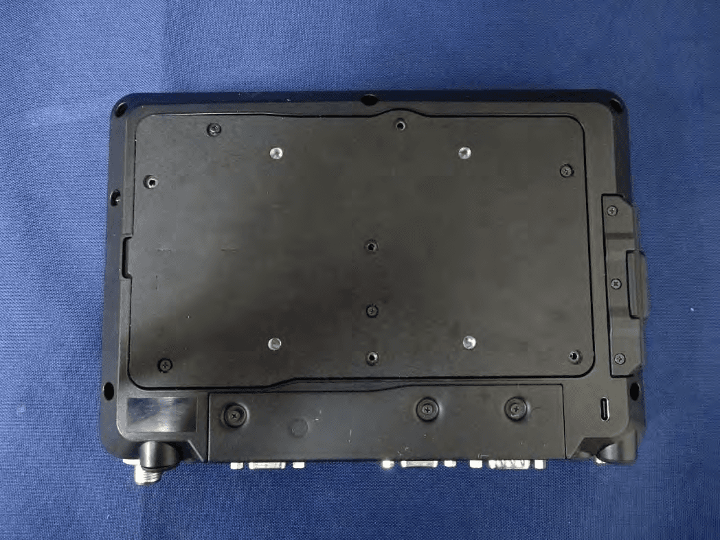
Report No:1470210R-SAUSP44V00 Page: 3 of 23 EUT Photographs Report No:1470210R-SAUSP44V00 Page: 4 of 23 Report No:1470210R-SAUSP44V00 Page: 5 of 23
ID Label/Location Info
RuggON Corporation FCC ID.: 2ABTU-PM-522 3F., No.129, Minquan Rd., Xindian Dist., New Taipei City 23141, Taiwan.Tel : +886 2 8797-1778 FCC ID Label
ID Label/Location Info
RuggON Corporation FCC ID.: 2ABTU-PM-522 3F., No.129, Minquan Rd., Xindian Dist., New Taipei City 23141, Taiwan.Tel : +886 2 8797-1778 The FCC ID Label will be placed on the equipment as shown in the photograph below.
Internal Photos
Report No.: 1470210R-RFUSP69V00 Page : 5 of 26 (8) EUT Photo (9) EUT Photo Report No.: 1470210R-RFUSP69V00 Page : 6 of 26 (10) EUT Photo (11) EUT Photo NFC Antenna GPS AntennaWLAN Aux + BT Antenna WLAN Main Antenna WLAN+BT Module NFC Module GPS Module Report No.: 1470210R-RFUSP69V00 Page : 7 of 26 (12) EUT Photo (13) EUT Photo-WLAN+BT Module Report No.: 1470210R-RFUSP69V00 Page : 8 of 26 (14) EUT Photo (15) EUT Photo Report No.: 1470210R-RFUSP69V00 Page : 9 of 26 (16) EUT Photo (17) EUT Photo Report No.: 1470210R-RFUSP69V00 Page : 10 of 26 (18) EUT Photo (19) EUT Photo Report No.: 1470210R-RFUSP69V00 Page : 11 of 26 (20) EUT Photo (21) EUT Photo Report No.: 1470210R-RFUSP69V00 Page : 12 of 26 (22) EUT Photo (23) EUT Photo Report No.: 1470210R-RFUSP69V00 Page : 13 of 26 (24) EUT Photo (25) EUT Photo Report No.: 1470210R-RFUSP69V00 Page : 14 of 26 (26) EUT Photo (27) EUT Photo-GPS Report No.: 1470210R-RFUSP69V00 Page : 15 of 26 (28) EUT Photo (29) EUT Photo-NFC Module Report No.: 1470210R-RFUSP69V00 Page : 16 of 26 (30) EUT Photo (31) EUT Photo Report No.: 1470210R-RFUSP69V00 Page : 17 of 26 (32) EUT Photo (33) EUT Photo Report No.: 1470210R-RFUSP69V00 Page : 18 of 26 (34) EUT Photo (35) EUT Photo Report No.: 1470210R-RFUSP69V00 Page : 19 of 26 (36) EUT Photo (37) EUT Photo Report No.: 1470210R-RFUSP69V00 Page : 20 of 26 (38) EUT Photo (39) EUT Photo-GPS Antenna Report No.: 1470210R-RFUSP69V00 Page : 21 of 26 (40) EUT Photo (41) EUT Photo Report No.: 1470210R-RFUSP69V00 Page : 22 of 26 (42) EUT Photo (43) EUT Photo Report No.: 1470210R-RFUSP69V00 Page : 23 of 26 (44) EUT Photo-WLAN+BT Antenna (45) EUT Photo-WLAN+BT Antenna Report No.: 1470210R-RFUSP69V00 Page : 24 of 26 (46) EUT Photo-NFC Antenna (47) EUT Photo Report No.: 1470210R-RFUSP69V00 Page : 25 of 26 (48) EUT Photo (49) EUT Photo Report No.: 1470210R-RFUSP69V00 Page : 26 of 26 (50) EUT Photo
Test Report
Report No. 1470210R-RFUSP17V00 Page: 1 of 28 FCC Test Report Product Name TABLET PC Model No. PM-522 FCC ID 2ABTU-PM-522 Applicant RuggON Corporation Address 3F., No.129, Minquan Rd., Xindian Dist., New Taipei City 23141, Taiwan Date of Receipt July. 08, 2014 Issued Date Aug. 11, 2014 Report No. 1470210R-RFUSP17V00 Report Version V1.0 The test results relate only to the samples tested. The test results shown in the test report are traceable to the national/international standard through the calibration of the equipment and evaluated measurement uncertainty herein. This report must not be used to claim product endorsement by TAF or any agency of the government. The test report shall not be reproduced without the written approval of QuieTek Corporation. Report No. 1470210R-RFUSP17V00 Page: 2 of 28 Test Report Issued Date: Aug. 11, 2014 Report No.: 1470210R-RFUSP17V00 Product Name TABLET PC Applicant RuggON Corporation Address 3F., No.129, Minquan Rd., Xindian Dist., New Taipei City 23141, Taiwan Manufacturer Ubiqconn Technology,Inc. Model No. PM-522 FCC ID. 2ABTU-PM-522 EUT Rated Voltage AC 100-240V, 50-60Hz EUT Test Voltage AC 120V/60Hz Trade Name RuggON Applicable Standard FCC CFR Title 47 Part 15 Subpart C: 2013 ANSI C63.10: 2009 Test Result Complied Documented By : ( Senior Adm. Specialist / Genie Chang ) Tested By : ( Engineer / Jerry Tsai ) Approved By : ( Director/ Vincent Lin ) Report No. 1470210R-RFUSP17V00 Page: 3 of 28 TABLE OF CONTENTS Description Page 1. GENERAL INFORMATION .....................................................................................................4 1.1. EUT Description............................................................................................................................4 1.2. Operational Description ................................................................................................................5 1.3. Tested System Datails....................................................................................................................6 1.4. Configuration of tested System .....................................................................................................6 1.5. EUT Exercise Software .................................................................................................................7 1.6. Test Facility ...................................................................................................................................8 2. Conducted Emission....................................................................................................................9 2.1. Test Equipment..............................................................................................................................9 2.2. Test Setup ......................................................................................................................................9 2.3. Limits ..........................................................................................................................................10 2.4. Test Procedure .............................................................................................................................10 2.5. Uncertainty ..................................................................................................................................10 2.6. Test Result of Conducted Emission.............................................................................................11 3. Radiated Emission .....................................................................................................................13 3.1. Test Equipment............................................................................................................................13 3.2. Test Setup ....................................................................................................................................13 3.3. Limits ..........................................................................................................................................14 3.4. Test Procedure .............................................................................................................................15 3.5. Uncertainty ..................................................................................................................................16 3.6. Test Result of Radiated Emission................................................................................................17 4. Band Edge ..................................................................................................................................20 4.1. Test Equipment............................................................................................................................20 4.2. Test Setup ....................................................................................................................................20 4.3. Limits ..........................................................................................................................................21 4.4. Test Procedure .............................................................................................................................21 4.5. Uncertainty ..................................................................................................................................21 4.6. Test Result of Band Edge ............................................................................................................22 5. Frequency Tolerance .................................................................................................................23 5.1. Test Equipment............................................................................................................................23 5.2. Test Setup ....................................................................................................................................23 5.…
Text truncated - open the document above for the full version.
Test Setup Photos
Report No.: 1470210R-RFUSP69V00 Page : 1 of 4 Attachment 1: EUT Test Setup Photographs Front View of Radiated Test Back View of Radiated Test Report No.: 1470210R-RFUSP69V00 Page : 2 of 4 Front View of Radiated Test Back View of Radiated Test Report No.: 1470210R-RFUSP69V00 Page : 3 of 4 Front View of Radiated Test (Horn) Back View of Radiated Test (Horn) Report No.: 1470210R-RFUSP69V00 Page : 4 of 4 Front View of Radiated Test (Horn) Back View of Radiated Test (Horn)
Contact Information
Applicant
Jay Wu(Manager)
Technical Contact
QuieTek CorporationMaggie Chen
[email protected]886-2-8601-3788
No.5-22, Rueishu Keng, Linkou Dist., · Taiwan
Non-Technical Contact
QuieTek CorporationMaggie Chen
[email protected]886-2-8601-3788
Test Firm
DEKRA TESTING AND CERTIFICATION CO., LTD. LinKouMirenda Liao
Technical Specifications
| # | Rule Parts | Frequency Range | Power Output |
|---|---|---|---|
| 1 | 15C | 13.56 MHz - 13.56 MHz | - |
Other Applications from RuggON Corporation
2ABTU-MT7030
Aug 12, 2020Mobile Data Terminal
Equipment Class
DXX - Part 15 Low Power Communication Device Transmitter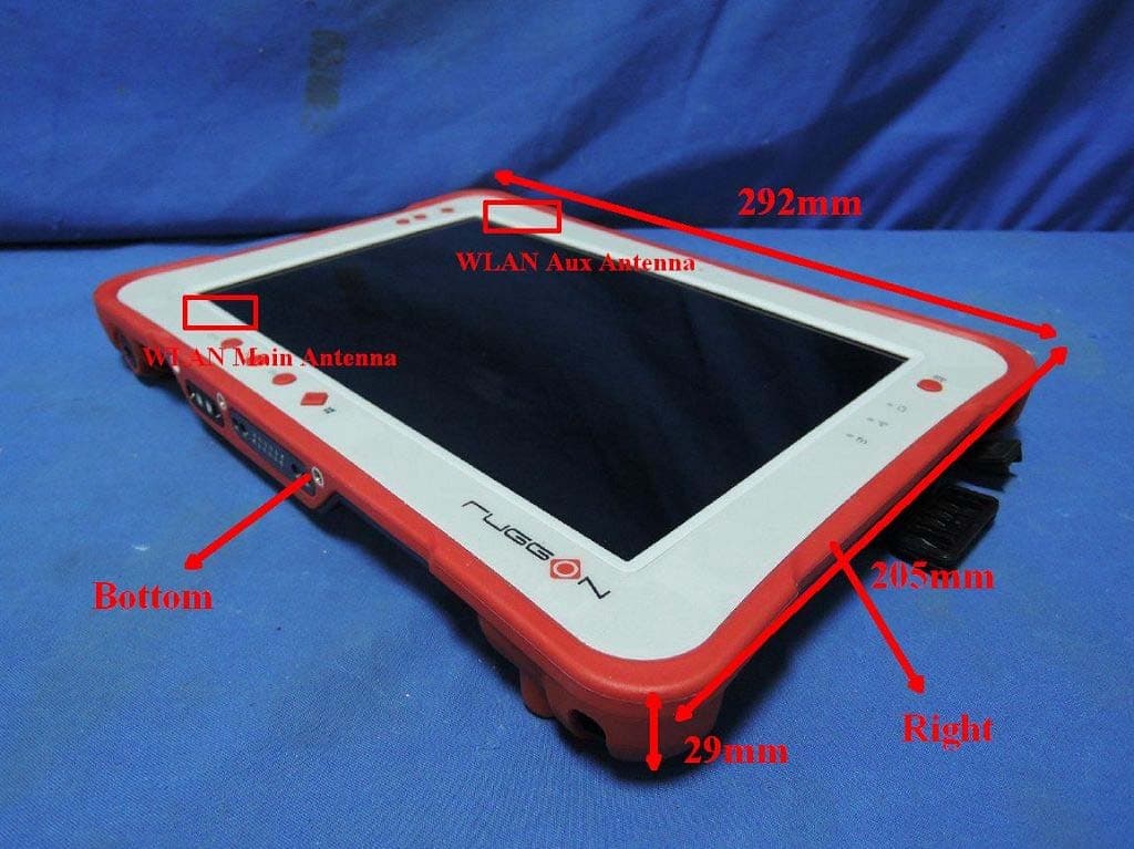
2ABTU-PM-521
Mar 05, 2015TABLET PC
Equipment Class
DXX - Part 15 Low Power Communication Device Transmitter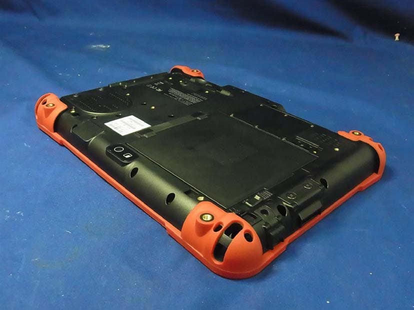
2ABTU-PX-501
Mar 01, 2015TABLET PC
Equipment Class
DSS - Part 15 Spread Spectrum Transmitter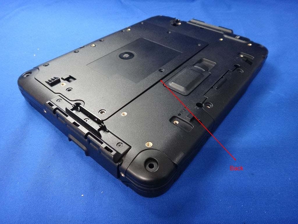
2ABTU-PA-301
Apr 07, 2014TABLET PC
Equipment Class
DTS - Digital Transmission System