2ABWHPCPP380AEAS System
Callidus trading, spol. s r.o.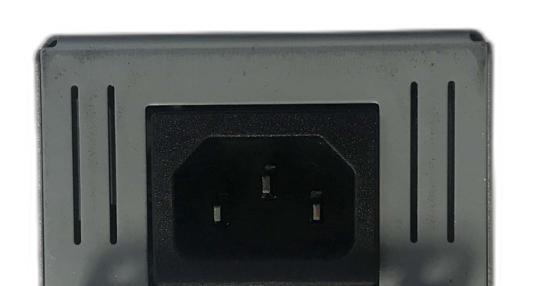
Click to zoom
Application Details
- Equipment Class
- DCD - Part 15 Low Power Transmitter Below 1705 kHz
- Date of Grant
- Feb 16, 2023
- Application Purpose
- Original Equipment
- Date of Application
- Feb 16, 2023
- Equipment Note
- EAS System
- Frequency Range
- 0.05800000 - 0.05800000
- Country
- Czech Republic
Documents & Files
Document Text
Text extracted from the exhibit documents filed with the FCC. Open a document above to read the original.
Users Manual
AM TRX UNIT ACOUSTO-MAGNETIC SECURITY SYSTEM (AM_TRX_FW_v4.0) Version 4.2 July 2022 INSTALLATION AND SERVICE GUIDE CALLIDUS TRADING, spol. s r.o. Page - 2 This document was created to provide intended recipient documentation of requested device for technician purposes only. Any other usage of this document is an illegal and unlawful act. This document is a confidential and proprietary document and consist of information what can be protected by copyrights or the others intellectual property protection instruments of the others subjects. All other information, what are not generally known ones, is an intellectual property. This document including any and all attachments hereto is intended solely to be used by individual or entity to which it is addressed. If the reader of this document is not the intended recipient, or an employee or agent responsible for delivering this document to its intended recipient, you are herewith notified that any dissemination, distribution, copying or retention of this document or the information contained herein is strictly prohibited. If you have received this document in error, please immediately and permanently delete and destroy the original and any copy or printout thereof. • Remote maintenance and diagnostics • ShopMonitor connectivity • Visitor counting • Alarm validating • Additional alarm outputs • Additional binary input • Jammer detector • Permanent magnet detection • Booster Bag detection • Tag too close indication • and much more... 1. Operation guidelines...................................................................................................................................................................................................................................... 4 2. Basic informations ......................................................................................................................................................................................................................................... 4 3. Pre-install tasks ............................................................................................................................................................................................................................................. 4 3.1 AM pedestal system placement .............................................................................................................................................................................................................. 4 3.2 Installation equipment of AM pedestal systems in one entrance ........................................................................................................................................................... 4 4. Specifications ................................................................................................................................................................................................................................................. 4 4.1 Electrical ................................................................................................................................................................................................................................................. 4 4.2 Mechanical ............................................................................................................................................................................................................................................. 5 5. Mounting AM pedestal system – general recommendation .......................................................................................................................................................................... 5 5.1 Pedestals installation and placement ..................................................................................................................................................................................................... 5 5.2 Sources of interference ........................................................................................................................................................................................................................... 5 5.3 Pedestals cables and wiring ................................................................................................................................................................................................................... 6 5.4 Routing the cables .................................................................................................................................................................................................................................. 6 5.5 Connection schematic and detection field .............................................................................................................................................................................................. 9 6. AM TRX electronic board ..............................................................................................................................................................................................................................10 7. El. board setting connection .........................................................................................................................................................................................................................11 7.1 HW key connection ................................................................................................................................................................................................................................11 7.2 Connecting to the PC/Laptop.................................................................................................................................................................................................................11 8. Software description ........…
Text truncated - open the document above for the full version.
External Photos
Complete set CPP+ 380 AM TRX, ISO, white Top View of EUT Bottom View of the EUT Side View of the EUT
ID Label/Location Info
FCC ID: 2ABWHPCPP380A This device complies with Part 15 of the FCC Rules. Operation is subject to the following two conditions: (1) This device may not cause harmful interference and (2) This device must accept any interference received, including interference that may cause undesired operation. IC: 29314-PCPP380A Le présent appareil est conforme aux CNR d’Industrie Canada applicables aux appareils radio exempts de licence. L’exploitation est autorisée aux deux conditions suivantes: (1) l’appareil ne doit pas produire de brouillage, et (2) l’utilisateur de l’appareil doit accepter tout brouillage radioélectrique subi, même si le brouillage est susceptible d’en compromettre le fonctionnement.
Internal Photos
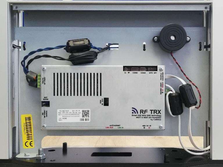
AM TRX board, BOTTOM AM TRX board, TOP AM TRX board CPP+ 380 AM TRX, FRONT CPP+ 380 AM TRX, REAR LED People counter, BOTTOM People counter, TOP Piezo
Test Report
Antenna Information for CPP+380 AM TRX 1.General description There are two loops. Every loop dimensions are 740x340mm with 12 turns. The impedance of the loop is 80 ohms.
Test Report
Report Number: B20729D2 FCC Part 15 Subpart B and FCC Section 15.209; ICES-003, RSS-210 & RSS-GEN Test Report EAS system Model: CPP+380 AM TRX Brea Division 114 Olinda Drive Brea, CA 92823 (714) 579-0500 Newbury Park Division 1050 Lawrence Drive Newbury Park, CA 91320 (805) 480-4044 Lake Forest Division 20621 Pascal Way Lake Forest, CA 92630 (949) 587-0400 Page 1 of 22 FCC PART 15, SUBPART B and C; ICES-003, RSS-210 & RSS-GEN TEST REPORT for EAS system Model: CPP+380 AM TRX Prepared for Callidus trading, spol. s r.o. Pašerových 1270/1 709 00 Ostrava - Mariánské Hory, Česká republika Prepared by:_____________________ JAMES ROSS Approved by:____________________ KYLE FUJIMOTO COMPATIBLE ELECTRONICS INC. 114 OLINDA DRIVE BREA, CALIFORNIA 92823 (714) 579-0500 DATE: DECEMBER 6, 2022 REPORT APPENDICES TOTAL BODY A B C D E PAGES 22 2 2 2 11 14 53 This report shall not be reproduced except in full, without the written approval of Compatible Electronics. Report Number: B20729D2 FCC Part 15 Subpart B and FCC Section 15.209; ICES-003, RSS-210 & RSS-GEN Test Report EAS system Model: CPP+380 AM TRX Brea Division 114 Olinda Drive Brea, CA 92823 (714) 579-0500 Newbury Park Division 1050 Lawrence Drive Newbury Park, CA 91320 (805) 480-4044 Lake Forest Division 20621 Pascal Way Lake Forest, CA 92630 (949) 587-0400 Page 2 of 22 TABLE OF CONTENTS Section / Title PAGE GENERAL REPORT SUMMARY 4 SUMMARY OF TEST RESULTS 5 1. PURPOSE 6 1.1 Decision Rule & Risk 7 2. ADMINISTRATIVE DATA 8 2.1 Location of Testing 8 2.2 Traceability Statement 8 2.3 Cognizant Personnel 8 2.4 Date Test Sample was Received 8 2.5 Disposition of the Test Sample 8 2.6 Abbreviations and Acronyms 8 3. APPLICABLE DOCUMENTS 9 4. DESCRIPTION OF TEST CONFIGURATION 10 4.1 Description of Test Configuration - Emissions 10 4.1.1 Cable Construction and Termination 10 5. LISTS OF EUT, ACCESSORIES AND TEST EQUIPMENT 12 5.1 EUT and Accessory List 12 5.2 Emissions Test Equipment 13 6. TEST SITE DESCRIPTION 14 6.1 Test Facility Description 14 6.2 EUT Mounting, Bonding and Grounding 14 6.3 Measurement Uncertainty 15 7. TEST PROCEDURES 16 7.1 RF Emissions 16 7.1.1 Radiated Emissions (Spurious and Harmonics) Test – Lab A 16 7.1.2 Radiated Emissions (Spurious and Harmonics) Test – Lab D 17 7.1.3 Conducted Emissions Test 18 7.1.4 RF Emissions Test Results 19 7.1.5 Sample Calculations 20 7.1.6 Variation of the Input Power 21 8. CONCLUSIONS 22 Report Number: B20729D2 FCC Part 15 Subpart B and FCC Section 15.209; ICES-003, RSS-210 & RSS-GEN Test Report EAS system Model: CPP+380 AM TRX Brea Division 114 Olinda Drive Brea, CA 92823 (714) 579-0500 Newbury Park Division 1050 Lawrence Drive Newbury Park, CA 91320 (805) 480-4044 Lake Forest Division 20621 Pascal Way Lake Forest, CA 92630 (949) 587-0400 Page 3 of 22 LIST OF APPENDICES APPENDIX TITLE A Laboratory Accreditations and Recognitions B Modifications to the EUT C Models Covered Under This Report D Diagrams and Charts Test Setup Diagrams Antenna and Effective Gain Factors E Data Sheets LIST OF FIGURES FIGURE TITLE 1 Plot Map And Layout of Radiated Site 2 Layout of the Semi-Anechoic Test Chamber 3 Conducted Emissions Test Setup LIST OF TABLES TABLE TITLE 1 Radiated Emission Results 2 Conducted Emission Results Report Number: B20729D2 FCC Part 15 Subpart B and FCC Section 15.209; ICES-003, RSS-210 & RSS-GEN Test Report EAS system Model: CPP+380 AM TRX Brea Division 114 Olinda Drive Brea, CA 92823 (714) 579-0500 Newbury Park Division 1050 Lawrence Drive Newbury Park, CA 91320 (805) 480-4044 Lake Forest Division 20621 Pascal Way Lake Forest, CA 92630 (949) 587-0400 Page 4 of 22 GENERAL REPORT SUMMARY This electromagnetic emission test report is generated by Compatible Electronics Inc., which is an independent testing and consulting firm. The test report is based on testing performed by Compatible Electronics personnel according to the measurement procedures described in the test specifications given below and in the "Test Procedures" section of this report. The measurement data and conclusions appearing herein relate only to the sample tested and this report may not be reproduced without the written permission of Compatible Electronics, unless done so in full. This report must not be used to claim product certification, approval or endorsement by NVLAP, NIST or any agency of the federal government. Device Tested: EAS system Model: CPP+380 AM TRX P/N: 18-501.CP S/N: P0098142 Product Description: The device is used in pairs at a 6-foot distance apart creating an AM detection field in between them. Once an undeactivated AM label/tag is detected in the detection field, the EUT triggers a visual and an acoustic alarm. ○ EUT operating frequencies: 0.057 – 0.059 MHz ○ Operating frequencies: 32.768 kHz and 25 MHz,. ○ Dimensions: 38.2 cm (W) x 5.5 cm (D) x 168 cm (H) Modifications: The EUT was not modified during the testing. Customer: Callidus trading, spol. s r.o. Pašerových 1270/1 709 00 Ostrava - Mariánské Hory, Česká republika Test Date: July 26, 28, and 29, 2022 Test Specifications : Emissions requirements CFR Title 47, Part 15, Subpart B, sections 15.107 and 15.109; Subpart C, sections 15.205, 15.207, and 15.209; ICES-003, RSS-210 and RSS-Gen Test Procedure: ANSI C63.4 and ANSI C63.10 Test Deviations: The test procedure was not deviated from during the testing. Report Number: B20729D2 FCC Part 15 Subpart B and FCC Section 15.209; ICES-003, RSS-210 & RSS-GEN Test Report EAS system Model: CPP+380 AM TRX Brea Division 114 Olinda Drive Brea, CA 92823 (714) 579-0500 Newbury Park Division 1050 Lawrence Drive Newbury Park, CA 91320 (805) 480-4044 Lake Forest Division 20621 Pascal Way Lake Forest, CA 92630 (949) 587-0400 Page 5 of 22 SUMMARY OF TEST RESULTS TEST DESCRIPTION RESULTS 1 Spurious Radiated RF Emissions, 9 kHz – 30 MHz (Transmitter and Digital portion) Complies with the limits of CFR Title 47, Part 15, Subpart C, section 15.205 and 15.209; and the limits of RSS-Gen and RSS-210 2 Spurious Radiated RF Emissions, …
Text truncated - open the document above for the full version.
Test Setup Photos
Report Number: B20729D2 FCC Part 15 Subpart B and FCC Section 15.209; ICES-003, RSS-210 & RSS-GEN Test Report EAS system Model: CPP+380 AM TRX Brea Division 114 Olinda Drive Brea, CA 92823 (714) 579-0500 Newbury Park Division 1050 Lawrence Drive Newbury Park, CA 91320 (805) 480-4044 Lake Forest Division 20621 Pascal Way Lake Forest, CA 92630 (949) 587-0400 Page D7 LAB A Callidus trading, spol. s r.o. EAS system Model: CPP+380 AM TRX FCC SUBPART B AND C, RSS-GEN, and RSS-210 – RADIATED EMISSIONS – BELOW 30 MHz PHOTOGRAPH SHOWING THE EUT CONFIGURATION FOR MAXIMUM EMISSIONS Radiated - Lab A - 58 kHz System - FCC RF - Lab D - 58 kHz System - FCC RR - Lab D - 58 kHz System - FCC CF - Lab D - 58 kHz System - FCC CR - Lab D - 58 kHz System - FCC
Contact Information
Applicant
Radim Hotovec(Managing Director)
Technical Contact
Compatible Electronics, Inc.Kyle Fujimoto
[email protected]714-579-0500
114 Olinda Drive · Brea, California · United States
Test Firm
Compatible Electronics, Inc.Ruby Hall
[email protected]805-480-4044
Technical Specifications
| # | Rule Parts | Frequency Range | Power Output |
|---|---|---|---|
| 1 | 15C | 0.058 MHz - 0.058 MHz | - |
Other Applications from Callidus trading, spol. s r.o.
2ABWHPCPP380R
Feb 16, 2023EAS System
Equipment Class
FAP - Part 15 Anti-Pilferage Device
2ABWHAS1000A
Feb 16, 2023AM Deactivator
Equipment Class
DCD - Part 15 Low Power Transmitter Below 1705 kHz