2ABZV-SG-7000Access Controlled Security System with zigbee&RFID
CHANG SHIN INFOTEL CO.,LTD
Click to zoom
Application Details
- Equipment Class
- DTS - Digital Transmission System
- Date of Grant
- Mar 20, 2014
- Application Purpose
- Original Equipment
- Date of Application
- Mar 20, 2014
- Equipment Note
- Access Controlled Security System with zigbee&RFID
- Frequency Range
- 2405.00000000 - 2480.00000000
- Company
- CHANG SHIN INFOTEL CO.,LTD
- Country
- South Korea
Documents & Files
Document Text
Text extracted from the exhibit documents filed with the FCC. Open a document above to read the original.
Users Manual
SG-MANAGER User manual http://www.csinfotel.com/ Page 1 SG-7000 User manual SG-MANAGER User manual http://www.csinfotel.com/ Page 2 Table of contents 2. Explanation of a screen. 2.1. Waiting screen. 2.2. ID/PW authentication screen. 2.3. Manager authentication screen. 2.4. Manager menu screen. 2.5. User management menu screen. 2.6. New registration screen. 2.7. Authentication success screen. 2.8. Authentication fail screen. 3. User registration process. 4. Initialization process. 5. User authentication process. 5.1. ID/PW authentication process. 5.2. W-Key authentication process. 5.3. Finger print authentication process. SG-MANAGER User manual http://www.csinfotel.com/ Page 3 1. Explanation of a screen. 1.1. Waiting screen. “Waiting screen’ is start-up screen. It shows various informations and waiting for authorization at the same time. By clicking the icon on this screen, it can be moved to “ID/PW authorization screen”, “Manager authentication screen”. Manager menu ICON ID/PW authentication ICON SG-MANAGER User manual http://www.csinfotel.com/ Page 4 1.2. ID/PW authentication screen. “ID/PW authentication screen” is the screen that authenticates by using user ID and password. This screen appears by clicking ID button on “waiting screen” 1.3. Manager authorization screen. “Manager authentication screen” appears when clicking manager icon on “waiting screen”, and it is screen to authorize manager before move to “manager menu screen”. Authorization method is the same as “1, 2 ID/PW authentication screen”. ID input box PW input box Remove button Enter button Home button Previous button SG-MANAGER User manual http://www.csinfotel.com/ Page 5 1.4. Manager menu screen. There are many icons on “manager menu screen” and it is moved to relevant function of screen by clicking one icon. User management screen Initialization screen SG-MANAGER User manual http://www.csinfotel.com/ Page 6 1.5. User management menu screen. “User management menu screen” is the screen that choose sub menu for manager`s management. There are “search/change/delete user” and “new registration” in sub menu. New registration screen SG-MANAGER User manual http://www.csinfotel.com/ Page 7 1.6. New registration screen. “New registration screen” is the screen that registers new user. Register “ID”, “PW”, “finger print” and “RFID Card” and “W-key” of user here. ID input box PW input box RFID Card registration status W-Key registration status Finger print registration status SG-MANAGER User manual http://www.csinfotel.com/ Page 8 1.7. Authentication succeed/fail screen. “Authentication succeed screen” appears when user normally succeeded authentication. This screen appears for a second and disappear. 1.8. Authentication fail screen. “인증 실패 화면”은 사용자가 인증을 시도했을 때, 인증이 실패한 경우 나타나는 화면이다. 이 화면은 1초간 나타났다 사라진다. SG-MANAGER User manual http://www.csinfotel.com/ Page 9 2. User registration process. User registration is performed in “user registration screen”. In order to move to “user registration screen”, it goes through “waiting screen” -> “Manager authentication screen” -> “user management menu screen” -> “New registration screen”. “ID” and “PW” section must be filled to register user. Finger print, RFID card and W-Key can be registered optionally. Order is not relevant in registration and registration method is explained in below. 2.1. Registration of RFID Card. It is done by tagging RFID Card in recognition spot. Once the registration is completed, below RFID Card icon is changed like below. Before registration Complete registration 2.2. Registration of W-Key. It can be done by clicking W-Key. Once the registration is completed, below W-Key icon is changed like below. Before registration Complete registration 2.3. Registration of finger print. It is done by putting finger on fingerprint scanner. Once the registration is completed, icon is changed like below. Before registration Complete registration 3. Initialization process. Clicking initialization icon in “manager menu screen” initializes all the settings of terminal, and user is deleted as well. 4. User authentication process. User authentication is available anytime on “waiting screen”. ID/PW is performed by moving to relevant screen by clicking “ID/PW” icon. 4.1. ID/PW authentication process. SG-MANAGER User manual http://www.csinfotel.com/ Page 10 4.1.1. Input ID. Input ID after clicking ID input box. <see image in “ID/PW authentication screen> 4.1.2. Input PW. Input PW after clicking PW input box. <see image in “ID/PW authentication screen> 4.1.3. Delete letter. Letter deleting button deletes inputting letter. <see image in “ID/PW authentication screen> 4.1.4. Request authentication. Perform authentication with input ID and PW by clicking “enter” button. <see image in “ID/PW authentication screen> 4.2. W-Key authentication process. 4.2.1. Authentication is performed by clicking W-Key button in “waiting screen”. 4.3. Finger print authentication process. 4.3.1. Authentication is performed by putting and removing finger on finger print scanner in “waiting list” Federal Communications Commission (FCC) Statement 15.21 You are cautioned that changes or modifications not expressly approved by the part responsible for compliance could void the user’s authority to operate the equipment. This device complies with Part 15 of the FCC Rules. Operation is subject to the following two conditions: 1) this device may not cause interference and 2) this device must accept any interference, including interference that may cause undesired operation of the device. 15.105(b) This equipment has been tested and found to comply with the limits for a Class B digital device, pursuant to part 15 of the FCC rules. These limits are designed to provide reasonable protection against harmful interference in a residential installation. This equipment generates, uses and can radiate radio frequency energy and, if not installed and used in accordance with the instructions, may cause harmful interference to radio comm…
Text truncated - open the document above for the full version.
Cover Letter(s)
Federal Communications Commission Authorization and Evaluation Division Applicant: CHANG SHIN INFOTEL CO.,LTD. Product: Access Controlled Security System Model: SG-7000 Address: 3F, Yonhap News Bldg, 64, Deadeok-Daero, 168beon-gil, seo-gu, Deajeon, South Korea SUBJECT: DoC for Access Controlled Security System To Whom It May Concern: We, the undersigned, hereby attest to the fact that we has been apply the Declaration of Conformity procedure to the class A, according to this product is a digital device (FCC ID: 2ABZV-SG-7000) of this composite filing. Sincerely, Date: 2014.03.17 Head Researcher: Han, Dong Soo
Cover Letter(s)
Federal Communications Commission Authorization and Evaluation Division Confidentiality Request regarding application for certification of FCC ID: 2ABZV-SG-7000 Pursuant to Sections 0.457 and 0.459 of the Commission’s Rules, we hereby request confidential treatment of information accompanying this application as outlined below: Exhibit Type File Name Block diagram Schematic diagram PCB Layout Part List Operation description Block diagram_SG-7000 Circuit Description_SG-7000 PCB Layout_SG-7000 Part list_SG-7000 Operation description_SG-7000 The above materials contain trade secrets and proprietary information not customarily released to the public. The public disclosure of these materials may be harmful to the applicant and provide unjustified benefits to its competitors. The applicant understands that pursuant to Section 0.457 and 0.459 of the Rules, disclosure of this application and all accompanying documentation will not be made before the date of the Grant for this application. Sincerely, Date: 2014.03.17 Head Researcher: Han, Dong Soo
External Photos
Head office & Test Lab: 180-254, Annyeong-dong, Hwaseong-si, Gyeonggi-do, South korea 445-380 Tel: +82-31-222-4251 / Fax: +82-31-222-4252 Report No: KST-FCR-140004 Page: 1 / 3 Appendix 2. Photographs of EUT [External View] Front Rear Head office & Test Lab: 180-254, Annyeong-dong, Hwaseong-si, Gyeonggi-do, South korea 445-380 Tel: +82-31-222-4251 / Fax: +82-31-222-4252 Report No: KST-FCR-140004 Page: 2 / 3 [ Right View ] [ Left View ] Head office & Test Lab: 180-254, Annyeong-dong, Hwaseong-si, Gyeonggi-do, South korea 445-380 Tel: +82-31-222-4251 / Fax: +82-31-222-4252 Report No: KST-FCR-140004 Page: 3 / 3 [ Top View ] [ Bottom View ]
ID Label/Location Info
Head office & Test Lab: 180-254, Annyeong-dong, Hwaseong-si, Gyeonggi-do, South korea 445-380 Tel: +82-31-222-4251 / Fax: +82-31-222-4252 Report No: KST-FCR-140004 Page: 1 / 2 Appendix 4. Sample Label & Location Label Information The following is a sample copy of the label that will be placed on Bottom side of the product. The FCC ID is marked in the product label with model No. and below information is visible printed on the label. Label location The label shown above shall be permanently affixed at a conspicuous location on the device and be readily visible to the user at the time purchase. The label is located here. Head office & Test Lab: 180-254, Annyeong-dong, Hwaseong-si, Gyeonggi-do, South korea 445-380 Tel: +82-31-222-4251 / Fax: +82-31-222-4252 Report No: KST-FCR-140004 Page: 2 / 2 Sub label Label location The label is located here.
Internal Photos
Head office & Test Lab: 180-254, Annyeong-dong, Hwaseong-si, Gyeonggi-do, South korea 445-380 Tel: +82-31-222-4251 / Fax: +82-31-222-4252 Report No: KST-FCR-140004 Page: 1 / 3 Appendix 3. Photographs of EUT [Internal View] [ Inside View ] Zigbee Antenna Head office & Test Lab: 180-254, Annyeong-dong, Hwaseong-si, Gyeonggi-do, South korea 445-380 Tel: +82-31-222-4251 / Fax: +82-31-222-4252 Report No: KST-FCR-140004 Page: 2 / 3 [Main board Front] [Main board Rear] Head office & Test Lab: 180-254, Annyeong-dong, Hwaseong-si, Gyeonggi-do, South korea 445-380 Tel: +82-31-222-4251 / Fax: +82-31-222-4252 Report No: KST-FCR-140004 Page: 3 / 3 [NFC board Front] [NFC board Rear]
Operational Description
1. Main antenna : 2405 MHz (green line: horizontal power) (red line: vertical power) 1.1 Horizontal Frequency(MHZ): 2405 Antenna Polarity: Horizontal Ma ximum Value(dBi): 2. 04 Average Gain(dBi) : -2.48 Minimum Gain(dBi): -55.18 1.2 Vertical Frequency(MHZ): 240 5 Antenna Polarity: Vertical M aximum Value(dBi): -4.51 Average Gain(dBi) : -8.98 Minimum Gain(dBi): -62.3 2. Main antenna : 244 0 MHz 2.1 Horizontal Frequency(MHZ): 244 0 Antenna Polarity: Horiz ontal Ma ximum Value(dBi): 1.94 Average Gain(dBi) : -2.44 Minimum Gain(dBi): -64.78 2.2 Vertical Frequency(MHZ): 244 0 Antenna Polarity: Vertical Maximum Value(dBi): -4.29 Average Gain(dBi) : -8.41 Minimum Gain(dBi): -47.4 2. Main antenna : 24 80 MHz 2.1 Horizontal Frequency(MHZ): 24 80 Antenna Polarity: Horiz ontal M a ximum Value(dBi): 1.53 Average Gain(dBi) : -4.34 Minimum Gain(dBi): -55.4 2.2 Vertical Frequency(MHZ): 24 80 Antenna Polarity: Ve rtical M a ximum Value(dBi): -4.95 Average Gain(dBi) : -14.06 Minimum Gain(dBi): -64.00
RF Exposure Info
Head office & Test Lab: 180-254, Annyeong-dong, Hwaseong-si, Gyeonggi-do, South korea 445-380 Tel: +82-31-222-4251 / Fax: +82-31-222-4252 RF Exposure Applicant: CHANG SHIN INFOTEL CO.,LTD. Product: Wireless identification Key System Model: SG-7000 FCC ID : 2ABZV-SG-7000 Radio Frequency Human Exposure Evaluation: The highest RF output power of the EUT at 2440 MHz was measured -15.21 dBm(0.03 mW) which is less than 20mW. Since maximum peak output power of the transmitter is <60/f (GHz) mW, i.e. 0.03mW<24.59(=60/2.440)mW, hence the EUT is excluded from SAR evaluation according to FCC KDB publication 447498 D01: Mobile Portable RF Exposure.
Test Report
Head office & Test Lab: 180-254, Annyeong-dong, Hwaseong-si, Gyeonggi-do, South korea 445-380 Tel: +82-31-222-4251 / Fax: +82-31-222-4252 Report No: KST-FCR-140004 Page: 2 / 27 KST-FCR-RFS-Rev.0.2 This report shall not be reproduced except in full without the written approval of KOSTEC Co., Ltd. Table of Contents 1. GENERAL INFORMATION ............................................................................................................ 3 1.1 Test Facility ............................................................................................................................................... 3 1.2 Location .................................................................................................................................................... 3 2. EQUIPMENT DESCRIPTION ........................................................................................................ 4 3. SYSTEM CONFIGURATION FOR TEST ....................................................................................... 5 3.1 Characteristics of equipment .................................................................................................................... 5 3.2 Used peripherals list ................................................................................................................................. 5 3.3 Product Modification ................................................................................................................................. 5 3.4 Operating Mode ........................................................................................................................................ 5 3.5 Test Setup of EUT .................................................................................................................................... 5 3.6 Table for Carrier Frequencies ................................................................................................................... 6 3.7 Used Test Equipment List ......................................................................................................................... 7 4. SUMMARY TEST RESULTS ......................................................................................................... 9 5. MEASUREMENT RESULTS ........................................................................................................ 10 5.1 Max. Conducted peak output power ....................................................................................................... 10 5.2 Conducted peak power spectral density ................................................................................................ 11 5.3 6 ㏈ spectrum Bandwidth ...................................................................................................................... 14 5.4 Band-edge Compliance of RF Conducted emissions ............................................................................ 16 5.5 Spurious RF Radiated emissions ........................................................................................................... 18 5.6 Antenna requirement .............................................................................................................................. 27 Head office & Test Lab: 180-254, Annyeong-dong, Hwaseong-si, Gyeonggi-do, South korea 445-380 Tel: +82-31-222-4251 / Fax: +82-31-222-4252 Report No: KST-FCR-140004 Page: 3 / 27 KST-FCR-RFS-Rev.0.2 This report shall not be reproduced except in full without the written approval of KOSTEC Co., Ltd. 1. GENERAL INFORMATION 1.1 Test Facility Test laboratory and address KOSTEC Co., Ltd. 180-254, Annyeong-dong, Hwaseong-si, Gyeonggi-do, South Korea The open area field test site and conducted measurement facility are used for these testing. This site at was fully described in a reports submitted to the Federal Communications Commission (FCC). The details of these reports have been found to be in complies with the requirements of Section 2.948 of the FCC Rules on November 14, 2002. The facility also complies with the radiated and conducted test site criteria set forth in ANSI C 63.10-2009. The Federal Communications Commission (FCC) has the reports on file and KOSTEC Co., Ltd. is listed under FCC Registration No.525762. The test site has been approved by the FCC for public use and is List in the FCC Public Access Link CORES (Commission Registration System) Registration information KCC (Korea Communications Commission) Number : KR0041 KOLAS(Korea Laboratory Accreditation Scheme) Number : 232 FCC Registration Number(FRN) : 525762 VCCI Registration Number : R-1657 / C –1763 IC Registration Site Number : 8305A-1 1.2 Location KOSTEC Co., Ltd. Head office & Test Lab: 180-254, Annyeong-dong, Hwaseong-si, Gyeonggi-do, South korea 445-380 Tel: +82-31-222-4251 / Fax: +82-31-222-4252 Report No: KST-FCR-140004 Page: 4 / 27 KST-FCR-RFS-Rev.0.2 This report shall not be reproduced except in full without the written approval of KOSTEC Co., Ltd. 2. EQUIPMENT DESCRIPTION The product specification described herein was declared by manufacturer. And refer to user’s manual for the details. 1) Equipment Name Access Controlled Security System 2) Model No SG-7000 3) Brand Name huinu 4) Usage Access Controlled Security System with ZIGBEE 5) Serial Number Prototype 6) ITU emission Code - 7) Oscillation Type PLL (Phase Local Loop) 8) Modulation Type CCK 9) Emission Type G1D 10) Maximum Power -15.21 ㏈m 11) Data Rate Max. 250 kbps 12) Operated Frequency 2 405 ㎒ ~ 2 480 ㎒ 13) Channel Number 16 14) Communication Type Half duplex 15) Final Amplifier U1102 16) Operation temperature -20 °C - + 50 °C 17) Power Source AC/DC Adaptor, output: DC 12 V 18) Antenna Description PCB antenna, Max. Gain: 2.04 ㏈i 19) FCC ID 2ABZV-SG-7000 ** it is maximum peak conducted power in band Head office & Test Lab: 180-254, Annyeong-dong, Hwaseong-si, Gyeonggi-do, South korea 445-380 Tel: +82-31-222-4251 / Fax: +82-31-222-4252 Report No: KST-FCR-140004 Page: 5 / 27 KS…
Text truncated - open the document above for the full version.
Test Setup Photos
Head office & Test Lab: 180-254, Annyeong-dong, Hwaseong-si, Gyeonggi-do, South korea 445-380 Tel: +82-31-222-4251 / Fax: +82-31-222-4252 Report No: KST-FCR-140004 Page: 1 / 3 Appendix 1. Photographs of test setup Radiated RF measurement (Below 30 ㎒) Radiated RF measurement (Above 30 ㎒) Head office & Test Lab: 180-254, Annyeong-dong, Hwaseong-si, Gyeonggi-do, South korea 445-380 Tel: +82-31-222-4251 / Fax: +82-31-222-4252 Report No: KST-FCR-140004 Page: 2 / 3 Radiated RF measurement (Above 1 ㎓) BLANK Head office & Test Lab: 180-254, Annyeong-dong, Hwaseong-si, Gyeonggi-do, South korea 445-380 Tel: +82-31-222-4251 / Fax: +82-31-222-4252 Report No: KST-FCR-140004 Page: 3 / 3 Conducted Emission (Front) Conducted Emission (Rear)
Contact Information
Applicant
Han Dong Soo(Head Researcher)
Test Firm
KOSTEC Co., LtdLee Chang-Ho
Technical Specifications
| # | Rule Parts | Frequency Range | Power Output |
|---|---|---|---|
| 1 | 15C | 2.40 GHz - 2.48 GHz | 30.00 µW |
Other Applications from CHANG SHIN INFOTEL CO.,LTD
2ABZV-SG-2100
Dec 13, 2015Access Controlled security system with Zigbee & RFID
Equipment Class
DTS - Digital Transmission System
2ABZV-SG-2200
Dec 13, 2015Access Controlled security system with Zigbee & RFID
Equipment Class
DTS - Digital Transmission System
2ABZV-SG-3000
Dec 22, 2014Access Controlled Security System with zigbee&RFID
Equipment Class
DXX - Part 15 Low Power Communication Device Transmitter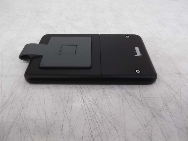
2ABZV-WKEY-2000
Mar 19, 2014WIRELESS IDENTIFICATION KEY SYSTEM WITH ZIGBEE
Equipment Class
DTS - Digital Transmission System