2AC4B-S4W1ShotTracker BLE Wrist Sensor
ShotTracker Inc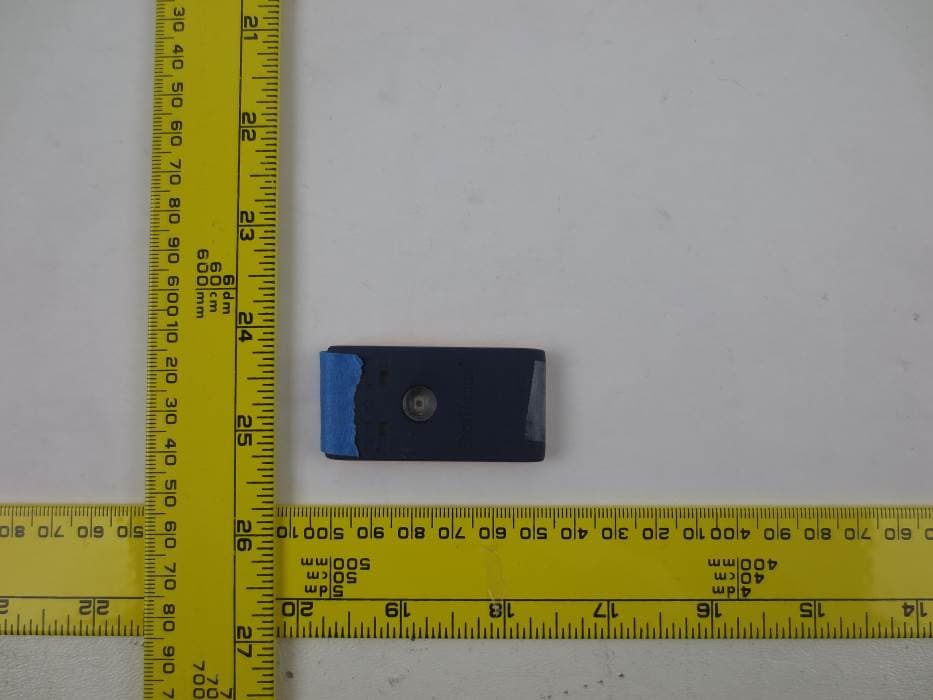
Click to zoom
Application Details
- Equipment Class
- DTS - Digital Transmission System
- Date of Grant
- Nov 14, 2014
- Application Purpose
- Original Equipment
- Date of Application
- Nov 14, 2014
- Equipment Note
- ShotTracker BLE Wrist Sensor
- Frequency Range
- 2402.00000000 - 2480.00000000
- Company
- ShotTracker Inc
- Country
- United States
Documents & Files
Document Text
Text extracted from the exhibit documents filed with the FCC. Open a document above to read the original.
Users Manual
USER GUIDE USER GUIDE Charging unit Net Sensor *side note: these units are in their proper charing positions WHAT’S IN THE BOX? 1 Wrist BandShooting Sleeve Charging cables 2 CHARGE IT UP CHARGING FOR THE FIRST TIME: Plug in your ShotTracker into an outlet using the included charging cable. The LED’s on the Net and Wrist sensor will turn RED when charging. The LED’s on the Net and Wrist sensor will turn GREEN when fully charged. A full charge takes about 4 hours. Charging your units : First insert your wrist sensor into the charging unit with the logo facing up. Then insert your net sensor into the charging unit with the blue facing up. The sensor lights will turn red when charging and green when charging is complete. You can charge your units together or individually. The net sensor has a much larger battery and will need to be charged approximately every three months) 3 APP TIME To get started, you’ll need to download the ShotTracker App. Visit your app store (Android or iOS) to download or scan the QR codes below. Once you have dowloaded the app, sign up and create your account. If you are under the age of 13, you will need parental consent. 4 SYNC YOUR DEVICES To get started, we need to sync and set up both devices to your app. If this is your first time, make sure both devices are fully charged. 1 2 3 4 Turn on the net sensor by shaking it a few times till it flashes green.Turn on the wrist sensor by holding on the power button till it flashes green. Using your app, let’s sync the devices. This can be found in the sign up flow or under Settings >> Sync Devices. Select the net sensor from the list and give it its own name it. Do the same for the wrist sensor. Both devices are successfully connected when you see a green check mark next to the wrist and net sensor. ***You cannot sync the devices while they are charging. 5 NET SENSOR Lower your basketball goal to it’s lowest setting for safety. Kids, if you cannot install the Net Sensor while standing, please get an adult to help with the installation. If a ladder is required, please follow the safety guidelines for the ladder. 1 2 Before installing your Net Sensor, make certain it has been successfully synced Open the net sensor by releasing the metal ring-clasp and lifting the blue lid. Insert the blue lid through a diamond in the back of the net, midway down from the rim. Position the Net Sensor so that the the knot is in the middle of the orange frame. Make sure the blue lid is facing the court and close the lid. A string should pass through the four orange channels beneath the sensor. Need some help? Check out our videos at ShotTracker.com/FAQ INSTALLING YOUR NET SENSOR: 6 WRIST SENSOR 1 2 Make sure your net sensor is on and has been synced with your app. Press the power button in the middle of the Wrist Sensor until ShotTracker flashes green to power on (approx. 3 seconds). Turn the wristband or shootIng sleeve inside-out and slide the wrist sensor into the pocket, bottom first with the underside (power connectors) facing up. INSTALLING YOUR WRIST SENSOR: 7 WRIST SENSOR 3 Then, flip the wrist band or shooting sleeve right side-in. The wrist sensor should now be in the correct position. Secure the wristband or shooting sleeve on your shooting arm. You’re ready to start! Need some help? Check out our videos at ShotTracker.com/FAQ 8 GET SHOOTING Once your Net Sensor and Wrist Sensor are connected with the app and properly installed, it’s time to train your ShotTracker. To train, you will take 5 shots from a location on the court (free throw line is recommended). Pressing the “shot” btn in the app aftershot. This indicates that a shot was taken and trains ShotTracker to your personal shot. You can train your ShotTracker once your have finished creating an account and syncing your devices. Settings >> Train My ShotTracker 9 HELPFUL HINTS Visit ShotTracker.com/FAQ for more information Powering On: Wrist Sensor: Hold down the power button until the ShotTracker logo blinks green. Net Sensor: Shake to wake (or shoot a few baskets) RED LED is on when charging GREEN LED is on when charging is complete Charge Time: Full charge takes about 4 hours 10 FCC STATEMENT This equipment has been tested and found to comply with the limits for a Class B digital device, pursuant to part 15 of the FCC Rules. These limits are designed to provide reasonable protection against harmful interference in a residential installation. This equipment generates, uses and can radiate radio frequency energy and, if not installed and used in accordance with the instructions, may cause harmful interference to radio communications. However, there is no guarantee that interference will not occur in a particular installation. If this equipment does cause harmful interference to radio or television reception, which can be determined by turning the equipment off and on, the user is encouraged to try to correct the interference by one or more of the following measures: — Reorient or relocate the receiving antenna. — Increase the separation between the equipment and receiver. — Connect the equipment into an outlet on a circuit different from that to which the receiver is connected. — Consult the dealer or an experienced radio/TV technician for help. 11 IC STATEMENT English This devices complies with Industry Canada license-exempt RSS standard(s). Operation is subject to the following two conditions: 1. This device may not cause harmful interference; 2. This device must accept any interference received, including interference that may cause undesired operation of the device. French Cet appareil est conforme à Industrie Canada une licence standard RSS exonérés (s). Son fonctionnement est soumis aux deux conditions suivantes: 1. Cet appareil ne doit pas provoquer d’interférences 2. Cet appareil doit accepter toute interférence reçue, y compris les interférences pouvant provoquer un fonctionnement indésirable de l’appareil 12 SHOTTRACKER.COM
Cover Letter(s)
QA-FR-170-B FCC Authorization 8/29/14 FEDERAL COMMUNICATIONS COMMISSIONS Authorization and Evaluation Division 7435 Oakland Mills Road Columbia, MD 21046 Subject: Agent Authorization To whom it may concern: We ShotTracker Inc , the undersigned, Hereby authorizes Bay Area Compliance Laboratories Corporation to act on its behalf in all matters relating to application for Equipment authorization, including the signing of all documents relating to these matters. All acts carried out by Bay Area Compliance Laboratory Corporation on our behalf shall have the same effect as our own action. We, the undersigned, hereby certify that we are not subject to a denial of federal benefits, that includes FCC benefits, pursuant to Section 5301 of the Anti-Drug Abuse Act of 1988, 21 U.S.C. 862. This authorization is valid until further written notice from the applicant. Sincerely Yours, COO/Co-founder 9105 Flint Overland Park KS 66214
Cover Letter(s)
QA-FR-172-A FCC Confidential Authorization 2014/09/01 FEDERAL COMMUNICATIONS COMMISSIONS Authorization and Evaluation Division 7435 Oakland Mills Road Columbia, MD 21046 Subject: Confidentiality Request regarding application for certification of FCC ID: 2AC4B- S4W1 In accordance with Sections 0.457 and 0.459 of the Commission’s Rules, ShotTracker Inc. hereby requests long-term confidential treatment of information accompanying this application as outlined below: • Block Diagram • Schematics • Operation Description As well as short-term confidential treatment of information accompanying this application as outlined below: • Internal Photos • User’s Manual • External Photos • Test Set-up Photos The above materials contain proprietary and confidential information not customarily released to the public. The public disclosure of these materials provides unjustified benefits to its competitors in the market. Sincerely, COO/Co-founder 9105 Flint Overland Park KS 66214
External Photos
ShotTracker Inc. . FCC ID: 2AC4B-S4W1, IC: 12327A-S4W1 Report Number: R1408251-247 Rev A Page 35 of 36 FCC Part 15C/ IC RSS- 210 Test Report 13 Exhibit C – EUT Photographs 13.1 EUT–Top View 13.2 EUT–Bottom View
Internal Photos
ShotTracker Inc. . FCC ID: 2AC4B-S4W1, IC: 12327A-S4W1 Report Number: R1408251-247 Rev A Page 36 of 36 FCC Part 15C/ IC RSS- 210 Test Report 13.3 EUT–PCB Top View 13.4 EUT–PCB Bottom View --- END OF REPORT ---
Test Report
Note: This test report is prepared for the customer shown above and for the device described herein. It may not be duplicated or used in part without prior written consent from Bay Area Compliance Laboratories Corp. This report must not be used by the customer to claim product certification, approval, or endorsement by A2LA*, NIST, or any agency of the Federal Government. * This report may contain data that are not covered by the A2LA accreditation and are marked with an asterisk “*” (Rev.2) FCC PART 15 SUBPART C IC RSS-210, ISSUE 8, DECEMBER 2010 TEST AND MEASUREMENT REPORT For ShotTracker Inc. 9105 Flint, Overland Park, KS 66214, USA Report Type: Original Report Product Type: ShotTracker BLE Wrist Sensor Prepared By: Chen Ge Report Number: R1408251-247 Rev A Report Date: 2014-11-04 Reviewed By: Bo Li Test En gineer Bay Area Compliance Laboratories Corp. 1274 Anvilwood Avenue, Sunnyvale, CA 94089, USA Tel: (408) 732-9162 Fax: (408) 732-9164 FCC ID: 2AC4B-S4W1 IC: 12327A-S4W1 ShotTracker Inc. . FCC ID: 2AC4B-S4W1, IC: 12327A-S4W1 Report Number: R1408251-247 Rev A Page 2 of 36 FCC Part 15C/ IC RSS- 210 Test Report TABLE OF CONTENTS 1 General Description ..................................................................................................................................................... 5 1.1 Product Description for Equipment Under Test (EUT) ...................................................................................... 5 1.2 Mechanical Description of EUT ......................................................................................................................... 5 1.3 Objective ............................................................................................................................................................. 5 1.4 Related Submittal(s)/Grant(s) ............................................................................................................................. 5 1.5 Test Methodology ............................................................................................................................................... 5 1.6 Measurement Uncertainty ................................................................................................................................... 5 1.7 Test Facility ........................................................................................................................................................ 6 2 System Test Configuration.......................................................................................................................................... 7 2.1 Justification ......................................................................................................................................................... 7 2.2 EUT Exercise Software....................................................................................................................................... 7 2.3 Special Equipment .............................................................................................................................................. 7 2.4 Equipment Modifications.................................................................................................................................... 7 2.5 Local Support Equipment ................................................................................................................................... 7 2.6 EUT Internal Configuration Details .................................................................................................................... 7 3 Summary of Test Results ............................................................................................................................................ 8 4 FCC §15.247(i), §2.1091 & IC RSS-102 – RF Exposure ........................................................................................... 9 4.1 Applicable Standards .......................................................................................................................................... 9 4.2 MPE Prediction ................................................................................................................................................. 10 4.3 MPE Results ..................................................................................................................................................... 10 5 FCC §15.203 & IC RSS-Gen §7.1.2 – Antenna Requirements ................................................................................ 11 5.1 Applicable Standards ........................................................................................................................................ 11 5.2 Antenna List ...................................................................................................................................................... 11 5.3 Result ................................................................................................................................................................ 11 6 FCC §15.209, §15.247(d) & IC RSS-210 §A8.5 – Spurious Radiated Emissions .................................................... 12 6.1 Applicable Standard .......................................................................................................................................... 12 6.2 Test Setup ......................................................................................................................................................... 13 6.3 Test Procedure .................................................................................................................................................. 13 6.4 Corrected Amplitude & Margin Calculation ..................................................................................................... 14 6.5 Test Equipment List and Details ........................................................................................…
Text truncated - open the document above for the full version.
Test Setup Photos
ShotTracker Inc. . FCC ID: 2AC4B-S4W1, IC: 12327A-S4W1 Report Number: R1408251-247 Rev A Page 33 of 36 FCC Part 15C/ IC RSS- 210 Test Report 12 Exhibit B – Test Setup Photographs 12.1 Radiated Emission below 1 GHz Front View 12.2 Radiated Emission below 1 GHz Rear View ShotTracker Inc. . FCC ID: 2AC4B-S4W1, IC: 12327A-S4W1 Report Number: R1408251-247 Rev A Page 34 of 36 FCC Part 15C/ IC RSS- 210 Test Report 12.3 Radiated Emission above 1 GHz Front View 12.4 Radiated Emission above 1 GHz Rear View
Contact Information
Applicant
Davyeon Ross(Co-founder / COO)
Test Firm
Bay Area Compliance Laboratories Corp.Lisa Tang
Technical Specifications
| # | Rule Parts | Frequency Range | Power Output |
|---|---|---|---|
| 1 | 15C | 2.40 GHz - 2.48 GHz | 5.00 mW |
Other Applications from ShotTracker Inc

2AC4B-S8D1
Feb 24, 2020WPTX Charger
Equipment Class
DTS - Digital Transmission System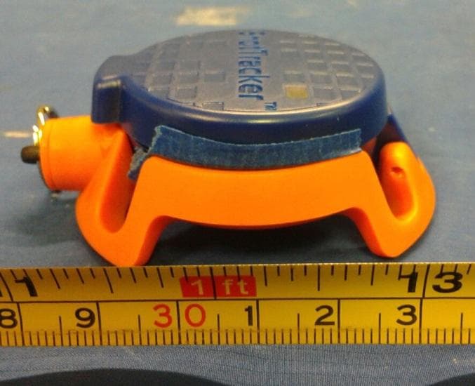
2AC4B-S5N1
Oct 08, 2015Net Sensor
Equipment Class
DTS - Digital Transmission System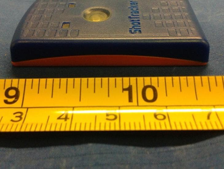
2AC4B-S5W1
Oct 08, 2015Wrist Sensor
Equipment Class
DTS - Digital Transmission System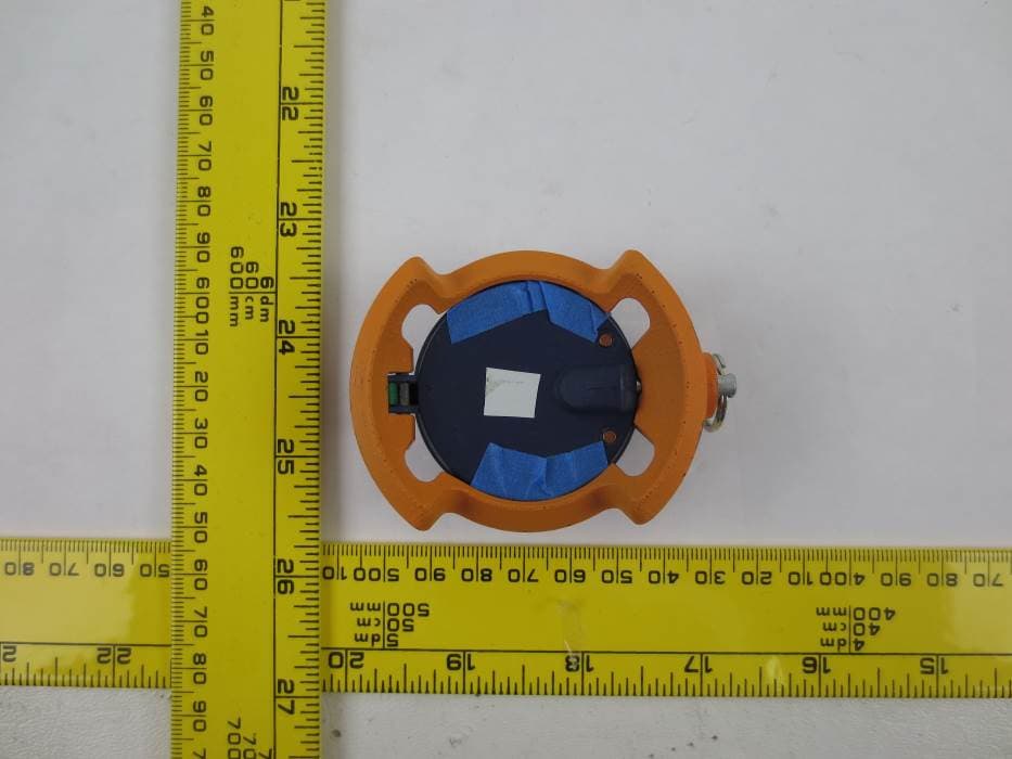
2AC4B-S4N1
Nov 14, 2014ShotTracker BLE Net Sensor
Equipment Class
DTS - Digital Transmission System