2AC4B-S5N1Net Sensor
ShotTracker Inc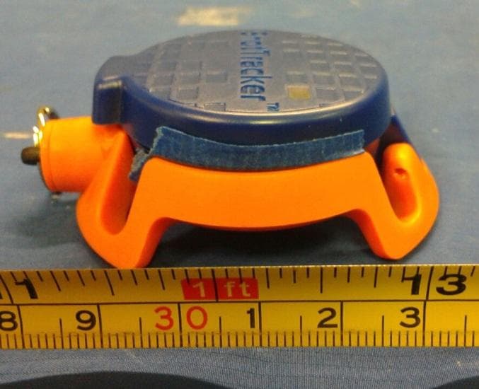
Click to zoom
Application Details
- Equipment Class
- DTS - Digital Transmission System
- Date of Grant
- Oct 08, 2015
- Application Purpose
- Original Equipment
- Date of Application
- Sep 22, 2015
- Equipment Note
- Net Sensor
- Frequency Range
- 2402.00000000 - 2480.00000000
- Company
- ShotTracker Inc
- Country
- United States
Documents & Files
Document Text
Text extracted from the exhibit documents filed with the FCC. Open a document above to read the original.
Users Manual
You can’t improve what you don’t measure, which is why we’ve created ShotTr acker: the wearable tech that automatically tr acks your shot attempts, makes and misses. ShotTr acker is made of 3 components: a wrist sensor, a net sensor and the ShotTr acker App. When a shooter shoots, the wrist sensor sends a signal that a shot was attempted. The net sensor sends a signal indicating if the shot was made or missed. Both signals are sent t o the mobile device where the ShotTr acker App keeps track of your shooting stats. NET SENSOR WRIST SENSOR SHOOTING SLEEVE WRIST BAND CHARGING UNIT CHARGING CABLE SOLD SEP ARA TELY First things first, you need to charge your S hotTr acker sensors. Your unit is shipped to you ready to charge; just needs to be plugged in. Plug the charging unit into a USB outlet using the charging cable. Place the wrist sensor in the charging unit so the charging contacts in the sensor match the charging contacts in the charger. The wrist sensor fits properly one direction in the charging unit, blue side facing up. CHARGING SHOTTRACKER APP Download the ShotTr acker app from your app store. To get started, you will need to create an account with ShotTr acker. The app will provide step-by-step videos and directions to get you set up and ready t o shoot. I f you need more assistance, check out our online support at support.shottr acker.c om. 1 2 3 4 1 2 Place the net sensor in the charging unit so the charging contacts in the sensor match the charging contacts in the charger. The net sensor fits properly one direction in the charging unit, blue side facing up. The LED’s on the sensors are RED when charging and GREEN when fully charged. YOUR UNIT SHOULD LOOK LIKE THIS WHILE CHARGING. OR (SELECT TO VIEW A VIDEO) *** Net Sensor battery lasts about 3 months. Wrist sensor battery lasts about 8 hours (continuous use) WRIST SENSOR To power on your wrist sensor, hold down the power button for 3 seconds. The LED light should blink green every few seconds if the wrist sensor is powered on. POWER ON SENSOR + WRISTBAND In your ShotTr acker App, go to Settings >> Wrist Sensor and select your wrist sensor fr om the list. The sensor you select will blink consecutively for 5 seconds. ***Both the net and wrist sensor must be connected with the app in order t o track shots. ***If you switch between your wristband and shooting sleeve, we reccommend you re-tr ain your S hotTr acker. Go to Settings >> Tr aining Profiles. ***If you switch between your wristband and shooting sleeve, we reccommend you re-tr ain your S hotTr acker. Go to Settings >> Tr aining Profiles. PAIR SENSOR TO APP Inside your wristband, there is a pocket. Slide your wrist sensor, blue side up, LED lights first, in to the wristband pocket. 1 Before you put your wrist sensor in to the sleeve or wrist band, make sure your wrist sensor is powered on and conencted to the app. Your wrist sensor should be double-blinking every few seconds. 2 Slide your wristband on to your shooting arm. The ShotTracker logo should be facing away from you. 3 (SELECT TO VIEW A VIDEO) SENSOR + SLEEVE Flip your sleeve inside out. Inside your sleeve is a pocket. Slide the wrist sensor, orange side up, arrow facing down, in to the shooting sleeve pocket. 1 Before you put your wrist sensor in to the sleeve or wrist band, make sure your wrist sensor is powered on and conencted to the app. Your wrist sensor should be double-blinking every few seconds. 2 Flip your shooting sleeve back to normal and slide it on to your shooting arm. The ShotTracker logo should be facing away from you. 3 NET SENSOR You can power on your net sensor by taking a couple shots or shaking it a few times. The LED light should blink green every few seconds if the net sensor is powered on. POWER ON ATTACHING THE NET SENSOR TO THE NET In your ShotTr acker App, go to Settings >> Net Sensor and select your net sensor fr om the list. The sensor you select will blink consecutively for 5 seconds. ***Both the net and wrist sensor must be connected with the app in order t o track shots. PAIR SENSOR TO APP Lower your basketball to it ‘s lowest setting to safely attach the net sensor. If you cannot reach the net while standing, please ask an adult to help. 1 Before you attach your net sensor to the net, make sure your net sensor is powered on and conencted to the app. Your net sensor should be double-blinking every few seconds. 2 Open the net sensor by releasing the metal ring clasp and lifting the blue lid. Positi on the net sensor on the back of the net. Center a knot in the middle of the orange frame so that a string passes through all four channels of the frame. The blue lid should face the court. Pull the ring down and close the blue lid. 3 4 5 (SELECT TO VIEW A VIDEO) *** To preserve battery, the net sensor turns off after 15 mins of no activity. ADDITIONAL SUPPORT Note: This equipment has been tested and found to comply with the limits for a Class B digital device, pursuant to part 15 of the FCC Rules. These limits are designed to provide reasonable protection against harmful interference in a residential installation. This equipment generates, uses and can radiate radio frequency energy and, if not installed and used in accordance with the instructions, may cause harmful interference to radio communications. However, there is no guarantee that interference will not occur in a particular installation. If this equipment does cause harmful interference to radio or television reception, which can be determined by turning the equipment off and on, the user is encouraged to try to correct the interference by one or more of the following measures: —Reorient or relocate the receiving antenna. —Increase the separation between the equipment and receiver. —Connect the equipment into an outlet on a circuit different from that to which the receiver is connected. —Consult the dealer or an experienced radio/TV technician for help. FCC Compliance Statement This device complies with part 15 of the FCC Rules. O…
Text truncated - open the document above for the full version.
Cover Letter(s)
775 Montague Expressway Milpitas, CA 95035 Tel: 408-526-1188 Fax: 408-526-1088 Email: [email protected] Project and Product Certification Representative Authorization Letter SCS-F18: Project and Product Certification Representative Authorization Letter Page 1 of 2 Rev 5.0 Reason for Amendment (current / obsolete) Revision History Approved Date FromTo Initial Release (obsolete)1.01.0Nov-14-2006 Revised wording (obsolete)1.02.0Sept–25-2007 Updated company template (obsolete)2.03.0Jan-31-2012 Updated letter information (obsolete)3.04.0May-23-2014 Added FCC ID field (current)4.05.0Sept 16 2014 9/15/2015 To: SIEMIC, Inc. 775 Montague Expressway, Milpitas, CA 95035 USA Dear Sir/Madam, Re: Project and Product Certification Representative Authorization Letter We, _____ShotTracker Inc._____hereby authorize SIEMIC, Inc. to act as Certification Body for certifying for the following project(s): Net Sensor, S5N1 FCC ID: 2AC4B-S5N1 We affirm that between SIEMIC, Inc. and ____ShotTracker Inc___, any difference in understanding, including test plan, measurement methods, applicable standards and relevant procedures and processes have been resolved prior to commencement of testing activities. Sincerely, Client’s signature Davyeon Ross co-founder / coo 9105 Flint Overland Park, KS 66214 SCS-F18: Project and Product Certification Representative Authorization Letter Page 2 of 2 Rev 5.0
Cover Letter(s)
775 Montague Expressway Milpitas, CA 95035 Tel: 408-526-1188 Fax: 408-526-1088 Email: [email protected] Confidentiality Request Letter SCS-F19: Confidentiality Request Letter Page 1 of 3Rev 4.0 Reason for Amendment (current / obsolete) Revision History Approved Date FromTo Initial Release (obsolete)1.01.0Nov-14-2006 Adding CFR 2.459 (obsolete)1.02.0August – 11 - 2008 Updated company template & Added text box (obsolete) 2.03.0Jan-31-2012 Added IC confidentiality letter form (current) 3.04.0March-26-2015 9/15/2015 To: Federal Communications Commission Authorization and Evaluation Division 7435 Oakland Mills Road Columbia, MD Subject: Permanent Confidentiality Request for FCC ID: 2AC4B-S5N1 We hereby request confidential treatment of information accompanying this application as outlined below: -Block Diagram -Schematics -Operational Description The above materials contain trade secrets and proprietary information not customarily released to the public. The public disclosure of these materials may be harmful to the applicant and provide unjustified benefits to its competitors. The applicant understands that pursuant to Section 0.457 & 0.459 of the Rules, disclosure of this application and all accompanying documentation will not be made before the date of the Grant for this application. Sincerely, Client’s signature : Davyeon Ross co-founder / coo 9105 Flint Overland Park, KS 66214 SCS-F19: Confidentiality Request Letter Page 2 of 3Rev 4.0
External Photos
EUT Photos - External EUT – Front View EUT – Rear View EUT – Left Side View EUT – Right Side View EUT – Top View EUT – Bottom View
ID Label/Location Info
Label Location
ID Label/Location Info
Wrist Sensor Label Information Here is the information that will be on the Wrist Sensor Label: 1 st line FCC logo, IC logo, no trash can logo 2 nd line “DESIGNED IN KANSAS” 3 rd line “FCC ID: 2AC4B-S5W1” 4 th line “ICC ID: 12327A-S5W1” 5 th line “MODEL: S5W1”
Internal Photos
EUT Photos – Internal EUT Cover Off View 1 Radio PCBA Top View PCBA Top View Battery Top View Battery Bottom View
RF Exposure Info
RF EXPOSURE CALCULATION RF EXPOSURE CALCULATION ______________________________________________________________________________________________________________________ According to § 15.247(e)(i) and § 1.1307(b)(1), systems operating under the provisions of this section shall be operated in a manner that ensures that the public is not exposed to radio frequency energy level in excess of the Commission’s guidelines. According to TCB Exclusions list, no SAR required if power is lower than the flowing threshold: Frequency Range Center frequency (MHz) 60/f SAR Limitation (mW) Low Frequency (MHz) High Frequency(MHz) 2402 2480 2440 25 Maximum measured transmitter power: Mode Conducted Power (mW) Max Antenna Gain (dBi) EIRP (mW) BTLE 1.958 1 3.217 Threshold at which no SAR required is 25 mW. Maximum Tx power is 3.217 mW EIRP. Conclusion: No SAR is required. Completed By: Teody Manansala SIEMIC, Inc 775 Montague Expressway, Milpitas, CA 95035 Phone: (408) 526-1188 Date: August 28, 2015
Test Report
775 Montague Expressway, Milpitas, CA 95035, USA • Phone: (+1) 408 526 1188 • Facsimile (+1) 408 526 1088 Visit us at: www.siemic.com; Follow us at: Report No.: FCC_RF_SL15080701-SHT-001_DTS Supersede Report No.: None Applicant : ShotTracker Inc. Product Name : Net Sensor Model No. : S5N1 Test Standard : 47 CFR 15.247 RSS-247 Issue 1.0 , May 2015 Test Method : ANSI C63.4: 2014 RSS-Gen Issue 4, Nov 2014 558074 D01 DTS Meas Guidance v03r02 FCC ID : 2AC4B-S5N1 IC ID : 12327A-S5N1 Dates of test : August 19, 2015 Issue Date : August 28, 2015 Test Result : ☒ Pass ☐ Fail Equipment complied with the specification [X] Equipment did not comply with the specification [ ] This Test Report is Issued Under the Authority of: Teody Manansala Chen Ge Test Engineer Engineer Reviewer Issued By: SIEMIC Laboratories 775 Montague Expressway, Milpitas, 95035 CA RF TEST REPORT Test report No. FCC_RF_SL15080701-SHT-001_DTS Page 2 of 36 775 Montague Expressway, Milpitas, CA 95035, USA • Phone: (+1) 408 526 1188 • Facsimile (+1) 408 526 1088 Visit us at: www.siemic.com; Follow us at: Laboratory Introduction SIEMIC, headquartered in the heart of Silicon Valley, with superior facilities in US and Asia, is one of the leading independent testing and certification facilities providing customers with one-stop shop services for Compliance Testing and Global Certifications. In addition to testing and certification, SIEMIC provides initial design reviews and compliance management throughout a project. Our extensive experience with China, Asia Pacific, North America, European, and International compliance requirements, assures the fastest, most cost effective way to attain regulatory compliance for the global markets. Accreditations for Conformity Assessment Country/Region Accreditation Body Scope USA FCC, A2LA EMC, RF/Wireless, Telecom Canada IC, A2LA, NIST EMC, RF/Wireless, Telecom Taiwan BSMI, NCC, NIST EMC, RF, Telecom, Safety Hong Kong OFTA, NIST RF/Wireless, Telecom Australia NATA, NIST EMC, RF, Telecom, Safety Korea KCC/RRA, NIST EMI, EMS, RF, Telecom, Safety Japan VCCI, JATE, TELEC, RFT EMI, RF/Wireless, Telecom Mexico NOM, COFETEL, Caniety Safety, EMC, RF/Wireless, Telecom Europe A2LA, NIST EMC, RF, Telecom, Safety Israel MOC, NIST EMC, RF, Telecom, Safety Accreditations for Product Certifications Country Accreditation Body Scope USA FCC TCB, NIST EMC, RF, Telecom Canada IC FCB, NIST EMC, RF, Telecom Singapore iDA, NIST EMC, RF, Telecom EU NB EMC & R&TTE Directive Japan MIC (RCB 208) RF, Telecom Hong Kong OFTA (US002) RF, Telecom Test report No. FCC_RF_SL15080701-SHT-001_DTS Page 3 of 36 775 Montague Expressway, Milpitas, CA 95035, USA • Phone: (+1) 408 526 1188 • Facsimile (+1) 408 526 1088 Visit us at: www.siemic.com; Follow us at: CONTENTS 1 REPORT REVISION HISTORY ....................................................................................................................................... 4 2 EXECUTIVE SUMMARY ................................................................................................................................................. 5 3 CUSTOMER INFORMATION .......................................................................................................................................... 5 4 TEST SITE INFORMATION ............................................................................................................................................ 5 5 MODIFICATION ............................................................................................................................................................. 5 6 EUT INFORMATION ...................................................................................................................................................... 6 6.1 EUT Description ........................................................................................................................................................ 6 Radio Description ............................................................................................................................................................... 6 Spec for BT Radio .............................................................................................................................................................. 6 6.2 EUT test modes/configuration Description.................................................................................................................... 6 6.3 EUT Photos - External ............................................................................................................................................... 7 6.4 EUT Photos – Internal ................................................................................................................................................ 8 6.5 EUT Test Setup Photos ............................................................................................................................................. 9 7 SUPPORTING EQUIPMENT/SOFTWARE AND CABLING DESCRIPTION ....................................................................... 10 7.1 Supporting Equipment ............................................................................................................................................. 10 7.2 Cabling Description ................................................................................................................................................. 10 7.3 Test Software Description ........................................................................................................................................ 10 8 TEST SUMMARY ......................................................................................................................................................... 11 9 MEASUREMENT UNCERTAINTY ................................................................................................................................. 12 10 MEASUREMENTS, EXAMINATION AND DERIVE…
Text truncated - open the document above for the full version.
Test Setup Photos
EUT Test Setup Photos AC Line Conducted Emissions – Front View AC Line Conducted Emissions – Rear View Radiated Emissions (<1GHz) – Front View Radiated Emissions (<1GHz) – Rear View Radiated Emissions (>1GHz) – Front View Radiated Emissions (<1GHz) – Rear View
Contact Information
Applicant
Davyeon Ross(Co-founder / COO)
Test Firm
Bureau Veritas Consumer Products Services, Inc.Sarb Shelopal
[email protected]+1 925 963 4420
Technical Specifications
| # | Rule Parts | Frequency Range | Power Output |
|---|---|---|---|
| 1 | 15C | 2.40 GHz - 2.48 GHz | 1.95 mW |
Other Applications from ShotTracker Inc

2AC4B-S8D1
Feb 24, 2020WPTX Charger
Equipment Class
DTS - Digital Transmission System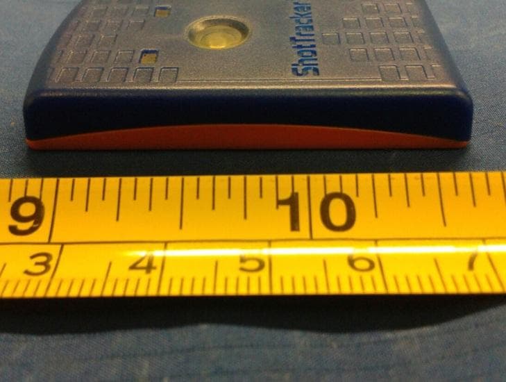
2AC4B-S5W1
Oct 08, 2015Wrist Sensor
Equipment Class
DTS - Digital Transmission System
2AC4B-S4W1
Nov 14, 2014ShotTracker BLE Wrist Sensor
Equipment Class
DTS - Digital Transmission System
2AC4B-S4N1
Nov 14, 2014ShotTracker BLE Net Sensor
Equipment Class
DTS - Digital Transmission System