2AC4B-S8D1WPTX Charger
ShotTracker Inc
Click to zoom
Application Details
- Equipment Class
- DTS - Digital Transmission System
- Date of Grant
- Feb 24, 2020
- Application Purpose
- Original Equipment
- Date of Application
- Feb 24, 2020
- Equipment Note
- WPTX Charger
- Frequency Range
- 2402.00000000 - 2480.00000000
- Company
- ShotTracker Inc
- Country
- United States
Documents & Files
Document Text
Text extracted from the exhibit documents filed with the FCC. Open a document above to read the original.
Users Manual
WIRELESS CHARGING POD OPERATING INSTRUCTIONS SHOTTRACKER.COM CHARGING PODCHARGING CORDSSHOTTRACKER BASKETBALL Plug in the charging pod with the cable provided. The lights on the charging pod should turn a solid BLUE. This indicates the charging pod is ready. To charge, place the basketball on the charging pod. Align the charging icon so that is sits directly centered on the charging pod icon. It is not recommended to hold the ball while charging. The charging pod lights display the ball battery level status: SOLID RED = Charging PULSING RED = Alignment Error (Make the sure charging icon is aligned) BLINKING RED = Error (Remove ball, wait for BLUE lights, and replace ball on charger) SOLID GREEN = Fully Charged SOLID BLUE = Ready for Ball 1 3 2 CHARGING ICON CHARGING LIGHTS Do NOT place anything but ShotTracker-enabled basketballs on the charging pod. This may result in harm to the charging pod. NOTE: This equipment has been tested and found to comply with the limits for a Class B digital device, pursuant to part 15 of the FCC Rules. These limits are designed to provide reasonable protection against harmful interference in a residential installation. Operation is subject to the following two conditions: (1) This device may not cause harmful interference, and (2) this device must accept any interference received, including interference that may cause undesired operation. This equipment generates, uses and can radiate radio frequency energy and, if not installed and used in accordance with the instructions, may cause harmful interference to radio communications. However, there is no guarantee that interference will not occur in a particular installation. If this equipment does cause harmful interference to radio or television reception, which can be determined by turning the equipment off and on, the user is encouraged to try to correct the interference by one or more of the following measures: – Reorient or relocate the receiving antenna. – Increase the separation between the equipment and receiver. – Connect the equipment into an outlet on a circuit different from that to which the receiver is connected. – Consult the dealer or an experienced radio/TV technician for help. CAUTION: Changes or modifications not expressly approved for compliance could void your authority to operate this equipment. ENGLISH This devices complies with Industry Canada license-exempt RSS standard(s). Operation is subject to the following two conditions: 1.This device may not cause harmful interference; 2.This device must accept any interference received, including interference that may cause undesired operation of the device. FRENCH Cet appareil est conforme à Industrie Canada une licence standard RSS exonérés (s). Son fonctionnement est soumis aux deux conditions suivantes:1. Cet appareil ne doit pas provoquer d’interférences2. Cet appareil doit accepter toute interférence reçue, y compris les interférences pouvant provoquer un fonctionnement indésirable de l’appareil. (f) UWB systems operating under the provisions of this section shall bear the following or similar statement in a conspicuous location on the device or in the instruction manual supplied with the device. This equipment may only be operated indoors. Operation outdoors is in violation of 47 U.S.C. 301 and could subject the operator to serious legal penalties. RF EXPOSURE WARNING STATEMENTS This equipment complies with FCC radiation exposure limits set forth for an uncontrolled environment. End users must follow the specific operating instructions for satisfying RF exposure compliance. Énoncé d’exposition aux rayonnements: Cet équipement est conforme aux limites d’exposition aux rayonnements ioniques RSS-102 Pour un environnement incontrôlé. The information in this guide may change without notice. The manufacturer assumes no responsibility for any errors that may appear in this guide. WIRELESS CHARGING POD SHOTTRACKER.COM
Cover Letter(s)
Cover Letter Date: 11/6/19 RE: FCC ID: 2AC4B-S8D1 To W h o m I t M a y C o n c e r n : Enclosed please find an FCC ID: 2AC4B-S8D1 certification application. This is a Bluetooth IEEE 802.15.1 type radio with wireless recharging capability seeking approval per CFR 47 Part 15.247 and CFR 47 Part 15.207 2018. Further details and supporting documents are attached. Should you have any questions, please feel free to contact the undersigned. Thank you for your attention to this matter. Signatory Davyeon Ross SHOTTRACKER.COM
Cover Letter(s)
Date: 10/22/19 Federal Communications Commission Authorization and Evaluation Division Confidentiality Request regarding application for certification of FCC ID: 2AC4B-S8D1 Pursuant to 47 CFR 0.459 and 0.457(d), we hereby request confidential treatment of information accompanying this application as outlined below: The above materials contain trade secrets and proprietary information not customarily released to the public. The public disclosure of these materials may be harmful to the applicant and provide unjustified benefits to its competitors. The applicant understands that pursuant to Section 0.457 of the Rules, disclosure of this application and all accompanying documentation will not be made before the date of the Grant for this application. Sincerely, Davyeon Ross Exhibit TypeFile Name Block Diagram Schematics Operational Description 2AC4B-S8D1 Block Diagram.pdf 2AC4B-S8D1 Schematic.pdf 2AC4B-S8D1 Operational Description.pdf SHOTTRACKER.COM
ID Label/Location Info
2AC4B-S8D1 LABEL SAMPLE 11.18.2019 SHOTTRACKER.COM DESIGNED IN K ANSAS FCC ID: 2AC4B-S8D1 IC: 12327A-S8D1 MODEL #: S8D1 STICKER PLACEMENT
Operational Description
SPE-13-8-007-J SWLP.2450.12.4.B.02 Description: 12*12*4mm 2.4GHz Wi-Fi SMD Patch Antenna Features: 2.4 - 2.5GHz Wi-Fi Patch Antenna For Wi-Fi/WLAN/ISM/Zigbee Industrial Applications High Gain 2dBi RoHS & Reach Compliant 2 SPE-13-8-007-J www.taoglas.com Taoglas makes no warranties based on the accuracy or completeness of the contents of this document and reserves the right to make changes to specifications and product descriptions at any time without notice. Taoglas reserves all rights to this document and the information contained herein. Reproduction, use or disclosure to third parties without express permission is strictly prohibited. 1. Introduction 3 2. Specifications 4 3. Antenna Characteristics 5 4. 2D Radiation Patterns 7 5. 3D Radiation Patterns 10 6. Mechanical Drawing 12 7. Evaluation Board 13 8. Packaging 14 3 SPE-13-8-007-J www.taoglas.com This 12*12*4mm high gain 2.4GHz patch antenna is ideally suited for high performance industrial applications in the 2.4GHz Wi-Fi, ISM, and Zigbee bands. This product has highest gain at broadside, most suitable for fixed wireless applications where transmission and reception is focused to one hemisphere of the device, for example a wireless meter on a reinforced concrete wall. It can also be placed anywhere on the device ground-plane, unlike most chip or loop antennas which need to be edge mounted. Many module manufacturers specify peak gain limits for any antennas that are to be connected to that module. Those peak gain limits are based on free-space conditions. In practice, the peak gain of an antenna tested in free-space can degrade by at least 1 or 2dBi when put inside a device. So ideally you should go for a slightly higher peak gain antenna than mentioned on the module specification to compensate for this effect, giving you better performance. Upon testing of any of our antennas with your device and a selection of appropriate layout, integration technique, or cable, Taoglas can make sure any of our antennas’ peak gain will be below the peak gain limits. Taoglas can then issue a specification and/or report for the selected antenna in your device that will clearly show it complying with the peak gain limits, so you can be assured you are meeting regulatory requirements for that module. For example, a module manufacturer may state that the antenna must have less than 2dBi peak gain, but you don’t need to select an embedded antenna that has a peak gain of less than 2dBi in free-space. This will give you a less optimized solution. It is better to go for a slightly higher free-space peak gain of 3dBi or more if available. Once that antenna gets integrated into your device, performance will degrade below this 2dBi peak gain due to the effects of GND plane, surrounding components, and device housing. If you want to be absolutely sure, contact Taoglas and we will test. Choosing a Taoglas antenna with a higher peak gain than what is specified by the module manufacturer and enlisting our help will ensure you are getting the best performance possible without exceeding the peak gain limits. 1. Introduction 1. Introduction 1. Introduction 1. Introduction 1. Introduction 1. Introduction 1. Introduction 1. Introduction 4 SPE-13-8-007-J www.taoglas.com Electrical Frequency Range 2400~2500MHz Bandwidth 100MHz @ -7dB Efficiency 80.12% @ Centre Freq. 2450MHz Polarization Linear VSWR 3.0 max @ Centre Freq. 2450MHz Peak Gain +2dBi typ. Impedance 50Ω Mechanical Dimensions 12*12*4mm Weight 4g Environmental Operating Temperature -40°C to +85°C Storage Temperature -40°C to +85°C Termination Ag (Environmentally Friendly Pb Free) 2. Specifications 3. Antenna Characteristics2. Specifications 3. Antenna Characteristics 4. Antenna Radiation Patterns3. Antenna Characteristics2. Specifications 3. Antenna Characteristics2. Specifications 3. Antenna Characteristics 4. Antenna Radiation Patterns3. Antenna Characteristics 4. Antenna Radiation Patterns 4. Antenna Radiation Patterns3. Antenna Characteristics 4. Antenna Radiation Patterns3. Antenna Characteristics2. Specifications 5 SPE-13-8-007-J www.taoglas.com 3.1 Return Loss 3.2 Efficiency -30 -25 -20 -15 -10 -5 0 20002100220023002400250026002700280029003000 (MHz) (dB) 3. Antenna Characteristics 4. Antenna Radiation Patterns3. Antenna Characteristics 4. Antenna Radiation Patterns 4. Antenna Radiation Patterns3. Antenna Characteristics 4. Antenna Radiation Patterns3. Antenna Characteristics 4. Antenna Radiation Patterns 4. Antenna Radiation Patterns 4. Antenna Radiation Patterns 4. Antenna Radiation Patterns3. Antenna Characteristics 4. Antenna Radiation Patterns3. Antenna Characteristics 6 SPE-13-8-007-J www.taoglas.com 3.3 Average Gain 3.4 Peak Gain 7 SPE-13-8-007-J www.taoglas.com 4. 4.1 Test Setup On Evaluation Board 4. 2D Radiation Patterns 4. Antenna Radiation Patterns 4. Antenna Radiation Patterns 4. Antenna Radiation Patterns 4. Antenna Radiation Patterns 4. Antenna Radiation Patterns 4. Antenna Radiation Patterns 4. Antenna Radiation Patterns Y X Z 8 SPE-13-8-007-J www.taoglas.com XY Plane XZ Plane -40 -30 -20 -10 0 10 0 30 60 90 120 150 180 210 240 270 300 330 (dB) 2400MHz 2450MHz 2500MHz Y -40 -30 -20 -10 0 10 0 30 60 90 120 150 180 210 240 270 300 330 (dB) 2400MHz 2450MHz 2500MHz X X Z 9 SPE-13-8-007-J www.taoglas.com YZ Plane -40 -30 -20 -10 0 10 0 30 60 90 120 150 180 210 240 270 300 330 (dB) 2400MHz 2450MHz 2500MHz Y Z 10 SPE-13-8-007-J www.taoglas.com 5.1 Free Space 2400MHz 2450MHz 5. 3D Radiation Patterns 4. Antenna Radiation Patterns 4. Antenna Radiation Patterns 4. Antenna Radiation Patterns 4. Antenna Radiation Patterns 4. Antenna Radiation Patterns 4. Antenna Radiation Patterns 4. Antenna Radiation Patterns 11 SPE-13-8-007-J www.taoglas.com 2500MHz 12 SPE-13-8-007-J www.taoglas.com 6. Mechanical Drawing (Units: mm) 6. Packaging5. Mechanical Drawing 6. Packaging 7. Application Note6. Packaging5. Mechanical Drawing 6. Packaging5. Mechanical Drawing 6. Packaging 7. Application Note6. Packaging 7. Applic…
Text truncated - open the document above for the full version.
RF Exposure Info
This report must not be used to claim product certification, approval, or endorsement by NVLAP, NIST, or any agency of the U.S. Government. This Report shall not be reproduced, except in full without written approval of the laboratory. EAR-Controlled Data - This document contains technical data whose export and reexport/retransfer is subject to control by the U.S. Department of Commerce under the Export Administration Act and the Export Administration Regulations. The Department of Commerce’s prior written approval may be required for the export or re- export/retransfer of such technical data to any foreign person, foreign entity or foreign organization whether in the United States or abroad. More: https://www.bis.doc.gov/index.php/forms-documents/regulations-docs/14-commerce-country-chart/fileT Shottracker WPTX FCC 2.1091:2019 Bluetooth Low Energy Report # SHOT0005.5 NVLAP Lab Code: 200630 CERTIFICATE OF EVALUATION 2018-09-14 Product compliance is the responsibility of the client; therefore, the tests and equipment modes of operation represented in this report were agreed upon by the client, prior to testing. The results of this test pertain only to the sample(s) tested. The specific description is noted in each of the individual sections of the test report supporting this certificate of test. This report reflects only those tests from the referenced standards shown in the certificate of test. It does not include inspection or verification of labels, identification, marking or user information. As indicated in the Statement of Work sent with the quotation, Element’s standard process is to always use the latest published version of the test methods even when earlier versions are cited in the test specification. Issuance of a purchase order was de facto acceptance of this approach. Otherwise, the client would have advised Element in writing of the specific version of the test methods they wanted applied to the subject testing Last Date of Evaluation: Friday, December 20, 2019 Shottracker EUT: WPTX RF Exposure Evaluation Standards Specification Method FCC 2.1091:2019 FCC 447498 D01 General RF Exposure Guidance v06 Results Method Clause Description Applied Results Comments 7.1 Maximum Permissible Exposure Yes Pass None Deviations From Evaluation Standards None Approved By: Donald Facteau, Process Architect Report No. SHOT0005.5EAR-Controlled Data2/9 ACCREDITATIONS AND AUTHORIZATIONS 2019.03.08 United States FCC - Designated by the FCC as a Telecommunications Certification Body (TCB). Certification chambers, Open Area Test Sites, and conducted measurement facilities are listed with the FCC. A2LA - Accredited by A2LA to ISO / IEC 17065 as a product certifier. This allows Element to certify transmitters to FCC and IC specifications. NVLAP - Each laboratory is accredited by NVLAP to ISO 17025 Canada ISED - Recognized by Innovation, Science and Economic Development Canada as a Certification Body (CB) and as a CAB for the acceptance of test data. European Union European Commission – Within Element, we have a EU Notified Body validated for the EMCD and RED Directives. Australia/New Zealand ACMA - Recognized by ACMA as a CAB for the acceptance of test data. Korea MSIT / RRA - Recognized by KCC’s RRA as a CAB for the acceptance of test data. Japan VCCI - Associate Member of the VCCI. Conducted and radiated measurement facilities are registered. Taiwan BSMI – Recognized by BSMI as a CAB for the acceptance of test data. NCC - Recognized by NCC as a CAB for the acceptance of test data. Singapore IDA – Recognized by IDA as a CAB for the acceptance of test data. Israel MOC – Recognized by MOC as a CAB for the acceptance of test data. Hong Kong OFCA – Recognized by OFCA as a CAB for the acceptance of test data. Vietnam MIC – Recognized by MIC as a CAB for the acceptance of test data. SCOPE For details on the Scopes of our Accreditations, please visit: https://www.nwemc.com/emc-testing-accreditations Report No. SHOT0005.5EAR-Controlled Data3/9 FACILITIES 2019.03.08 California Labs OC01-17 41 Tesla Irvine, CA 92618 (949) 861-8918 Minnesota Labs MN01-10 9349 W Broadway Ave. Brooklyn Park, MN 55445 (612)-638-5136 Oregon Labs EV01-12 6775 NE Evergreen Pkwy #400 Hillsboro, OR 97124 (503) 844-4066 Texas Labs TX01-09 3801 E Plano Pkwy Plano, TX 75074 (469) 304-5255 Washington Labs NC01-05 19201 120 th Ave NE Bothell, WA 98011 (425)984-6600 NVLAP NVLAP Lab Code: 200676-0 NVLAP Lab Code: 200881-0 NVLAP Lab Code: 200630-0 NVLAP Lab Code:201049-0 NVLAP Lab Code: 200629-0 Innovation, Science and Economic Development Canada 2834B-1, 2834B-3 2834E-1, 2834E-3 2834D-1 2834G-1 2834F-1 BSMI SL2-IN-E-1154R SL2-IN-E-1152R SL2-IN-E-1017 SL2-IN-E-1158R SL2-IN-E-1153R VCCI A-0029 A-0109 A-0108 A-0201 A-0110 Recognized Phase I CAB for ISED, ACMA, BSMI, IDA, KCC/RRA, MIC, MOC, NCC, OFCA US0158 US0175 US0017 US0191 US0157 Report No. SHOT0005.5EAR-Controlled Data4/9 REVISION HISTORY 2018.07.17 Revision Number Description Date (yyyy-mm-dd) Page Number 00 None Report No. SHOT0005.5EAR-Controlled Data5/9 PRODUCT DESCRIPTION 2018-07-17 Client and Equipment Under Evaluation Information Company Name: Shottracker Address: 7220 W. Frontage Rd. City, State, Zip: Merriam, KS 66203 Evaluation Requested By: Patrick Herron EUT: WPTX Date of Evaluation: Friday, December 20, 2019 Information Provided by the Party Requesting the Evaluation Functional Description of the Equipment: The WPTX wirelessly recharges ShotTracker-enabled rechargeable basketballs using a 6 MHz wireless power transfer technology under FCC 47 CFR part 18. A user places a basketball on the WPTX device, and when the WPTX indicates that the charge is complete, the user can remove the basketball and resume play. The WPTX contains a Bluetooth Low Energy Radio for out of bands communications. Objective: To demonstrate compliance with FCC requirements for RF exposure for 2.1091 mobile/fixed devices. Report No. SHOT0005.5EAR-Controlled Data6/9 RF Exposure Condition 2018-07-17 The foll…
Text truncated - open the document above for the full version.
Test Report
This report must not be used to claim product certification, approval, or endorsement by NVLAP, NIST, or any agency of the federal government of the United States of America. This Report shall not be reproduced, except in full without written approval of the laboratory. Shottracker WPTX FCC 15.247:2018 Bluetooth Low Energy (DTS) Radio Report # SHOT0005.1 NVLAP LAB CODE: 201049-0 CERTIFICATE OF TEST 2018-07-17 Product compliance is the responsibility of the client; therefore, the tests and equipment modes of operation represented in this report were agreed upon by the client, prior to testing. The results of this test pertain only to the sample(s) tested. The specific description is noted in each of the individual sections of the test report supporting this certificate of test. This report reflects only those tests from the referenced standards shown in the certificate of test. It does not include inspection or verification of labels, identification, marking or user information. Last Date of Test: July 26, 2018 Shottracker Model: WPTX Radio Equipment Testing Standards Specification Method FCC 15.207:2018 ANSI C63.10:2013, KDB 558074 FCC 15.247:2018 Results Method Clause Test Description Applied Results Comments 6.2 Powerline Conducted Emissions Yes Pass 11.12.1, 11.13.2, 6.5, 6.6 Spurious Radiated Emissions Yes Pass 11.6 Duty Cycle Yes Pass 11.8.2 Occupied Bandwidth Yes Pass 11.9.1.1 Output Power Yes Pass 11.10.2 Power Spectral Density Yes Pass 11.11 Band Edge Compliance Yes Pass 11.11 Spurious Conducted Emissions Yes Pass Deviations From Test Standards None Approved By: Jeremiah Darden, Operations Manager Report No. SHOT0005.12/46 REVISION HISTORY 2018.07.17 Revision Number Description Date Page Number 00 None Report No. SHOT0005.13/46 ACCREDITATIONS AND AUTHORIZATIONS 2018.07.17 United States FCC - Designated by the FCC as a Telecommunications Certification Body (TCB). Certification chambers, Open Area Test Sites, and conducted measurement facilities are listed with the FCC. A2LA - Accredited by A2LA to ISO / IEC 17065 as a product certifier. This allows Element to certify transmitters to FCC and IC specifications. NVLAP - Each laboratory is accredited by NVLAP to ISO 17025 Canada ISED - Recognized by Innovation, Science and Economic Development Canada as a Certification Body (CB). Certification chambers and Open Area Test Sites are filed with ISED. European Union European Commission – Within Element, we have a EU Notified Body validated for the EMCD and RED Directives. Australia/New Zealand ACMA - Recognized by ACMA as a CAB for the acceptance of test data. Korea MSIT / RRA - Recognized by KCC’s RRA as a CAB for the acceptance of test data. Japan VCCI - Associate Member of the VCCI. Conducted and radiated measurement facilities are registered. Taiwan BSMI – Recognized by BSMI as a CAB for the acceptance of test data. NCC - Recognized by NCC as a CAB for the acceptance of test data. Singapore IDA – Recognized by IDA as a CAB for the acceptance of test data. Israel MOC – Recognized by MOC as a CAB for the acceptance of test data. Hong Kong OFCA – Recognized by OFCA as a CAB for the acceptance of test data. Vietnam MIC – Recognized by MIC as a CAB for the acceptance of test data. SCOPE For details on the Scopes of our Accreditations, please visit: http://portlandcustomer.element.com/ts/scope/scope.htm http://gsi.nist.gov/global/docs/cabs/designations.html Report No. SHOT0005.14/46 FACILITIES 2018.07.17 California Labs OC01-17 41 Tesla Irvine, CA 92618 (949) 861-8918 Minnesota Labs MN01-10 9349 W Broadway Ave. Brooklyn Park, MN 55445 (612)-638-5136 New York Labs NY01-04 4939 Jordan Rd. Elbridge, NY 13060 (315) 554-8214 Oregon Labs EV01-12 6775 NE Evergreen Pkwy #400 Hillsboro, OR 97124 (503) 844-4066 Texas Labs TX01-09 3801 E Plano Pkwy Plano, TX 75074 (469) 304-5255 Washington Labs NC01-05 19201 120 th Ave NE Bothell, WA 98011 (425)984-6600 NVLAP NVLAP Lab Code: 200676-0 NVLAP Lab Code: 200881-0 NVLAP Lab Code: 200761-0 NVLAP Lab Code: 200630-0 NVLAP Lab Code:201049-0 NVLAP Lab Code: 200629-0 Innovation, Science and Economic Development Canada 2834B-1, 2834B-3 2834E-1, 2834E-3 N/A 2834D-1, 2834D-2 2834G-1 2834F-1 BSMI SL2-IN-E-1154R SL2-IN-E-1152R N/A SL2-IN-E-1017 SL2-IN-E-1158R SL2-IN-E-1153R VCCI A-0029 A-0109 N/A A-0108 A-0201 A-0110 Recognized Phase I CAB for ACMA, BSMI, IDA, KCC/RRA, MIC, MOC, NCC, OFCA US0158 US0175 N/A US0017 US0191 US0157 Report No. SHOT0005.15/46 MEASUREMENT UNCERTAINTY TMU.2015.07.10 Measurement Uncertainty When a measurement is made, the result will be different from the true or theoretically correct value. The difference is the result of tolerances in the measurement system that cannot be completely eliminated. To the extent that technology allows us, it has been our aim to minimize this error. Measurement uncertainty is a statistical expression of measurement error qualified by a probability distribution. A measurement uncertainty estimation has been performed for each test per our internal quality document QM205.4.6. The estimation is used to compare the measured result with its "true" or theoretically correct value. The expanded measurement uncertainty (K=2) can be found included as part of the applicable test description page. Our measurement data meets or exceeds the measurement uncertainty requirements of the applicable specification; therefore, the test data can be compared directly to the specification limit to determine compliance. The calculations for estimating measurement uncertainty are based upon ETSI TR 100 028 (or CISPR 16-4-2 as applicable), and are available upon request. The following table represents the Measurement Uncertainty (MU) budgets for each of the tests that may be contained in this report. Test + MU - MU Frequency Accuracy (Hz) 0.0007% -0.0007% Amplitude Accuracy (dB) 1.2 dB -1.2 dB Conducted Power (dB) 0.3 dB -0.3 dB Radiated Power via Substitution (dB) 0.7 dB -0.7 dB Temperature (degrees C) 0.7°C -0.7°C Humidity (% RH) 2.5% RH …
Text truncated - open the document above for the full version.
Test Setup Photos
POWERLINE CONDUCTED EMISSIONS WTD.2017.11.22.1 , SPURIOUS RADIATED EMISSIONS photo PSA-ESCI 2018.05.04 photos PSA-ESCI 2018.05.04 Spurious HF (1).JPG Spurious HF (2).JPG rious HF (2) SPURIOUS RADIATED EMISSIONS photo PSA-ESCI 2018.05.04 photos PSA-ESCI 2018.05.04 Spurious HF (3).JPG XMit 2017.12.13 Direct Connect (1).JPG Direct Connect (2).JPG DIRECT CONNECT XMit 2017.12.13 Direct Connect (3).JPG DIRECT CONNECT
Contact Information
Applicant
Davyeon Ross(Co-founder / COO)
Test Firm
Element Materials Technology DallasRenee Walker
Technical Specifications
| # | Rule Parts | Frequency Range | Power Output |
|---|---|---|---|
| 1 | 15C | 2.40 GHz - 2.48 GHz | 200.00 µW |
Other Applications from ShotTracker Inc
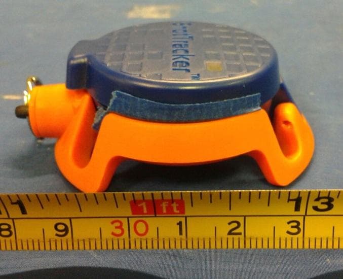
2AC4B-S5N1
Oct 08, 2015Net Sensor
Equipment Class
DTS - Digital Transmission System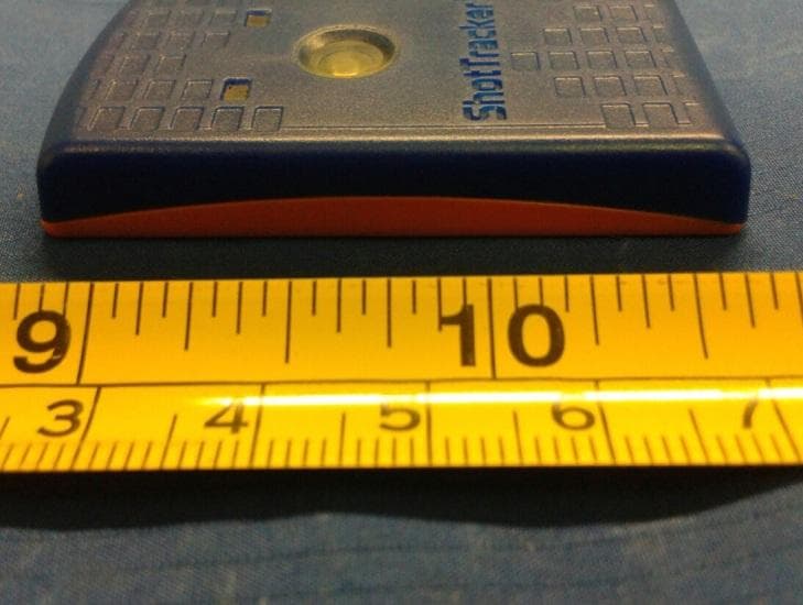
2AC4B-S5W1
Oct 08, 2015Wrist Sensor
Equipment Class
DTS - Digital Transmission System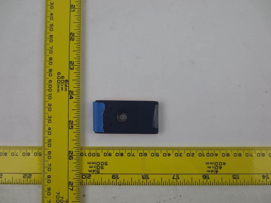
2AC4B-S4W1
Nov 14, 2014ShotTracker BLE Wrist Sensor
Equipment Class
DTS - Digital Transmission System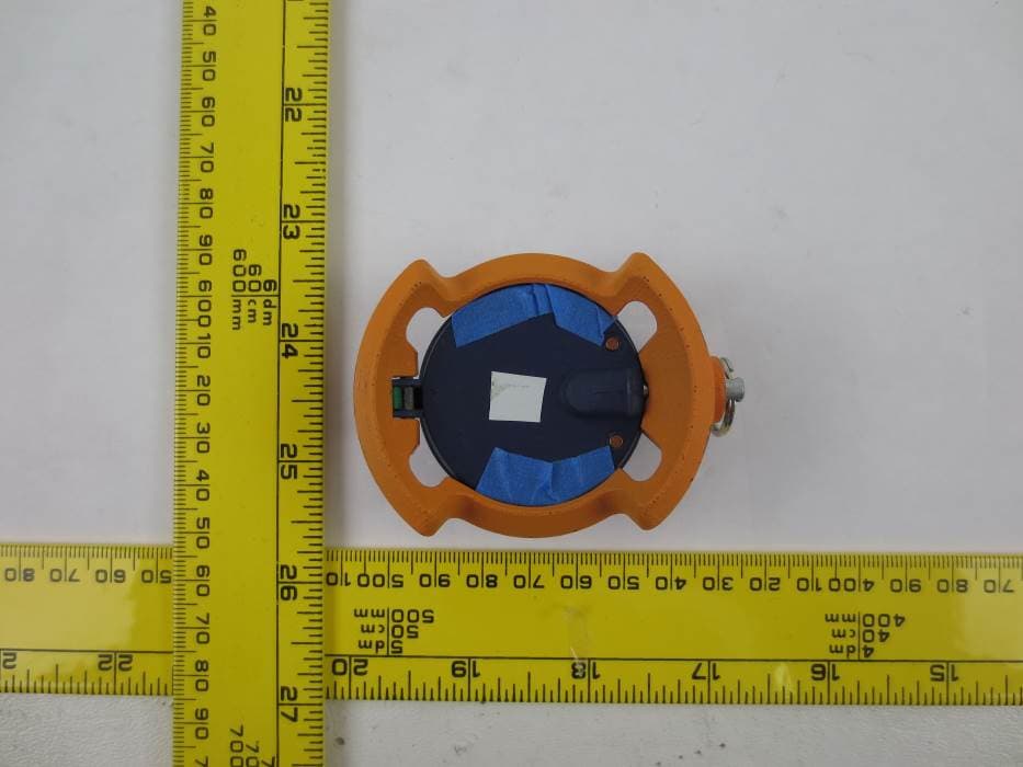
2AC4B-S4N1
Nov 14, 2014ShotTracker BLE Net Sensor
Equipment Class
DTS - Digital Transmission System