2AC6AC5PMobile Data Terminal with GSM, WCDMA, CDMA2000, LTE, WiFi, BT and RFID
Shenzhen Chainway Information Technology Co., Ltd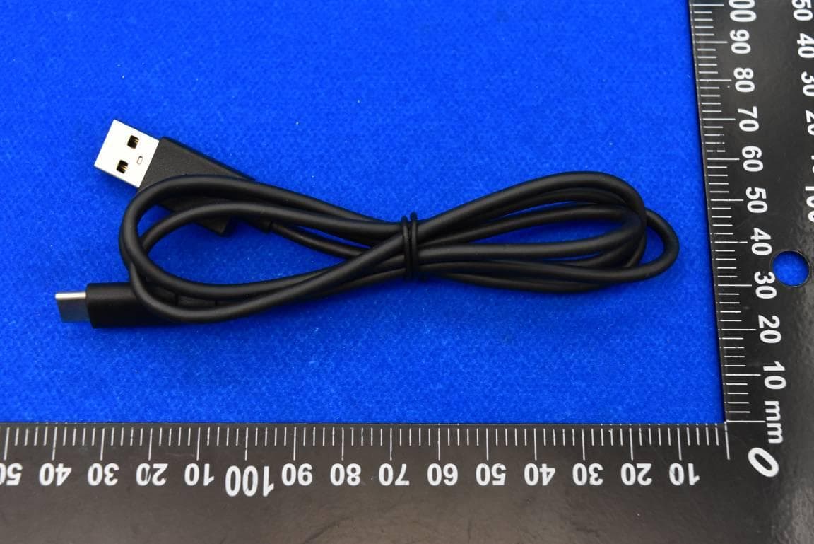
Click to zoom
Application Details
- Equipment Class
- NII - Unlicensed National Information Infrastructure TX
- Date of Grant
- Aug 05, 2023
- Application Purpose
- Original Equipment
- Date of Application
- Aug 03, 2023
- Equipment Note
- Mobile Data Terminal with GSM, WCDMA, CDMA2000, LTE, WiFi, BT and RFID
- Frequency Range
- 5745.00000000 - 5825.00000000
- Country
- China
Documents & Files
Document Text
Text extracted from the exhibit documents filed with the FCC. Open a document above to read the original.
Users Manual
SHENZHENCHAINWAYINFORMATIONTECHNOLOGYCO.,LTD HandheldRFIDReader C5UserManual 2 Contents Statement............................................................................................................................3 Chapter1ProductIntro.......................................................................................................4 1.1Intro.......................................................................................................................4 1.2Precautionbeforeusingbattery...........................................................................5 1.3Charger.................................................................................................................6 1.4Notes.....................................................................................................................7 Chapter2Installationinstructions.......................................................................................8 2.1Appearance...............................................................................................................8 2.2InstallMicroSDandSIMcards...............................................................................10 2.3Batterycharge.........................................................................................................11 2.4Buttonsandfunctionareadisplay...........................................................................12 Chapter3Callfunction.....................................................................................................13 3.1Callingnumbers......................................................................................................13 3.2Contacts...................................................................................................................13 3.3SMSandMMS........................................................................................................13 Chapter4Barcodereader-writer......................................................................................14 Chapter5RFIDreader.....................................................................................................16 5.1UHF.........................................................................................................................16 Chapter6Otherfunctions.................................................................................................17 6.1PINGtool.................................................................................................................17 6.2Bluetooth.................................................................................................................18 6.3GPS.........................................................................................................................19 6.4Volumesetup...........................................................................................................20 6.5Sensor.....................................................................................................................21 6.6Keyboard.................................................................................................................22 6.7Network....................................................................................................................23 Chapter7Devicecharacteristic........................................................................................24 Appendix...........................................................................................................................26 Restrictions:......................................................................................错误!未定义书签。 SimplifiedEUdeclarationofconformity...........................................错误!未定义书签。 SARInformation............................................................................... 错误!未定义书签。 3 Statement 2013byShenZhenChainwayInformationTechnologyCo.,Ltd.Allrightsreserved. Nopartofthispublicationmaybereproducedorusedinanyform,orbyanyelectricalor mechanicalmeans,withoutpermissionwrittenfromChainway.Thisincludeselectronic ormechanicalmeans,suchasphotocopying,recording,orinformationstorageand retrievalsystems.Thematerialinthismanualissubjecttochangewithoutnotice. Thesoftwareisprovidedstrictlyonan“asis”basis.Allsoftware,includingfirmware, furnishedtotheuserisonalicensedbasis.Chainwaygrantstotheuseranon- transferableandnon-exclusivelicensetouseeachsoftwareorfirmwareprogram deliveredhereunder(licensedprogram).Exceptasnotedbelow,suchlicensemaynot beassigned,sublicensed,orotherwisetransferredbytheuserwithoutpriorwritten consentofChainway.Norighttocopyalicensedprograminwholeorinpartisgranted, exceptaspermittedundercopyrightlaw.Theusershallnotmodify,merge,or incorporateanyformorportionofalicensedprogramwithotherprogrammaterial, createaderivativeworkfromalicensedprogram,orusealicensedprogramina networkwithoutwrittenpermissionfromChainway. Chainwayreservestherighttomakechangestoanysoftwareorproducttoimprove reliability,function,ordesign. Chainwaydoesnotassumeanyproductliabilityarisingoutof,orinconnectionwith,the applicationoruseofanyproduct,circuit,orapplicationdescribedherein. Nolicenseisgranted,eitherexpresslyorbyimplication,estoppel,orotherwiseunder anyChainwayintellectualpropertyrights.Animpliedlicenseonlyexistsforequipment, circuits,andsubsystemscontainedinChainwayproducts. 4 Chapter1ProductIntro 1.1Intro ChainwayC5isanupgradedall-in-onehigh-performanceUHFRFIDReader.Ithas Integratedaself-developedImpinjE710/R2000basedUHFmodulewhichoffers industry-leadingUHFperformance.C5adoptsanintegrateddesign,providesmore stableUHFperformance,anddelivershigherdurability.Thesuperiorsystem configurationofthemobilecomputerfeaturestheAndroid11platform,Qualcommocta- coreprocessor,optionalmassinternalmemoryandalargecapacityremovablebattery. C5alsosupports2Dscanning,NFC,fingerprintrecognitionandotherfunctions,which enablesittobewidelyusedinscenarioslikebanking,publicsecurity,warehousing, retail,logisticsandotherindustr…
Text truncated - open the document above for the full version.
External Photos
FCC ID: 2AC6AC5P External Photos 1. EUT front view 2. EUT rear view 3. EUT left side view 4. EUT right side view 5. EUT top view 6. EUT bottom view 7. Accessories
ID Label/Location Info
1 .Label 2 .Label location Paste on the device label size: 86.1*90.5mm
Internal Photos
FCC ID: 2AC6AC5P Internal Photos 1. EUT uncover view 2. Antenna view MAIN ANT RFID ANT DIV ANT GPS/BT/WIFI ANT
RF Exposure Info
MORLAB Shenzhen Morlab Communications Technology Co., Ltd. FL.1-3, Building A, FeiYang Science Park, No.8 LongChang Road, Block67, BaoAn District, ShenZhen , GuangDong Province, P. R. China Tel: 86-755-36698555 Fax: 86-755-36698525 Http://www.morlab.cn E-mail: [email protected] REPORT No.:SZ22120012S01 Annex C Plots of System Performance Check Test Laboratory: Shenzhen Morlab Communications Technology Co., Ltd. Date: 2022.03.04 System Check_750MHz_Head Communication System: UID 0, CW (0); Frequency: 750 MHz;Duty Cycle: 1:1 Medium: HSL_750 Medium parameters used: f = 750 MHz; σ = 0.892 S/m; ε r = 41.811; ρ = 1000 kg/m 3 Ambient Temperature:23.2 °C; Liquid Temperature:22.1 °C DASY5 Configuration: - Probe: EX3DV4 - SN7624; ConvF(10.43, 10.43, 10.43) @ 750 MHz; Calibrated: 2022.03.31 - Sensor-Surface: 2mm (Mechanical Surface Detection) - Electronics: DAE3 Sn373; Calibrated: 2022.12.28 - Phantom: Twin-SAM; Type: QD 000 P41 Ax; Serial: 2020 - Measurement SW: DASY52, Version 52.10 (4); SEMCAD X Version 14.6.14 (7483) CW750/Area Scan (61x61x1): Interpolated grid: dx=1.500 mm, dy=1.500 mm Maximum value of SAR (interpolated) = 3.61 W/kg CW750/Zoom Scan (5x5x7)/Cube 0: Measurement grid: dx=8mm, dy=8mm, dz=5mm Reference Value = 59.96 V/m; Power Drift = -0.08 dB Peak SAR (extrapolated) = 4.13 W/kg SAR(1 g) = 2.19 W/kg; SAR(10 g) = 1.42 W/kg Maximum value of SAR (measured) = 3.46 W/kg 0 dB = 3.61 W/kg MORLAB Shenzhen Morlab Communications Technology Co., Ltd. FL.1-3, Building A, FeiYang Science Park, No.8 LongChang Road, Block67, BaoAn District, ShenZhen, GuangDong Province, P. R. China Tel: 86-755-36698555 Fax: 86-755-36698525 Http://www.morlab.cn E-mail: [email protected] REPORT No.:SZ22120012S01 Test Laboratory: Shenzhen Morlab Communications Technology Co., Ltd. Date: 2022.03.08 System Check_900MHz_Head Communication System: UID 0, CW (0); Frequency: 900 MHz;Duty Cycle: 1:1 Medium: HSL_900 Medium parameters used: f = 900 MHz; σ = 0.951 S/m; ε r = 41.944; ρ = 1000 kg/m 3 Ambient Temperature:23.2 °C; Liquid Temperature:22.2 °C DASY5 Configuration: - Probe: EX3DV4 - SN7624; ConvF(10.1, 10.1, 10.1) @ 900 MHz; Calibrated: 2022.03.31 - Sensor-Surface: 2mm (Mechanical Surface Detection) - Electronics: DAE3 Sn373; Calibrated: 2022.12.28 - Phantom: Twin-SAM; Type: QD 000 P41 Ax; Serial: 2020 - Measurement SW: DASY52, Version 52.10 (4); SEMCAD X Version 14.6.14 (7483) CW900/Area Scan (61x61x1): Interpolated grid: dx=1.500 mm, dy=1.500 mm Maximum value of SAR (interpolated) = 4.37 W/kg CW900/Zoom Scan (5x5x7)/Cube 0: Measurement grid: dx=8mm, dy=8mm, dz=5mm Reference Value = 61.03 V/m; Power Drift = -0.10 dB Peak SAR (extrapolated) = 5.16 W/kg SAR(1 g) = 2.68 W/kg; SAR(10 g) = 1.75 W/kg Maximum value of SAR (measured) = 4.34 W/kg 0 dB = 4.37 W/kg MORLAB Shenzhen Morlab Communications Technology Co., Ltd. FL.1-3, Building A, FeiYang Science Park, No.8 LongChang Road, Block67, BaoAn District, ShenZhen, GuangDong Province, P. R. China Tel: 86-755-36698555 Fax: 86-755-36698525 Http://www.morlab.cn E-mail: [email protected] REPORT No.:SZ22120012S01 Test Laboratory: Shenzhen Morlab Communications Technology Co., Ltd. Date: 2023.03.04 System Check_1800MHz_Head Communication System: UID 0, CW (0); Frequency: 1800 MHz;Duty Cycle: 1:1 Medium: HSL_1800 Medium parameters used: f = 1800 MHz; σ = 1.419 S/m; ε r = 40.289; ρ = 1000 kg/m 3 Ambient Temperature:23.2 °C; Liquid Temperature:22.1 °C DASY5 Configuration: - Probe: EX3DV4 - SN7624; ConvF(8.6, 8.6, 8.6) @ 1800 MHz; Calibrated: 2022.03.31 - Sensor-Surface: 2mm (Mechanical Surface Detection) - Electronics: DAE3 Sn373; Calibrated: 2022.12.28 - Phantom: Twin-SAM; Type: QD 000 P41 Ax; Serial: 2020 - Measurement SW: DASY52, Version 52.10 (4); SEMCAD X Version 14.6.14 (7483) CW1800/Area Scan (61x61x1): Interpolated grid: dx=1.500 mm, dy=1.500 mm Maximum value of SAR (interpolated) = 14.5 W/kg CW1800/Zoom Scan (5x5x7)/Cube 0: Measurement grid: dx=8mm, dy=8mm, dz=5mm Reference Value = 90.77 V/m; Power Drift = -0.11 dB Peak SAR (extrapolated) = 17.7 W/kg SAR(1 g) = 10.11 W/kg; SAR(10 g) = 5.19 W/kg Maximum value of SAR (measured) = 13.8 W/kg 0 dB = 14.5 W/kg MORLAB Shenzhen Morlab Communications Technology Co., Ltd. FL.1-3, Building A, FeiYang Science Park, No.8 LongChang Road, Block67, BaoAn District, ShenZhen, GuangDong Province, P. R. China Tel: 86-755-36698555 Fax: 86-755-36698525 Http://www.morlab.cn E-mail: [email protected] REPORT No.:SZ22120012S01 Test Laboratory: Shenzhen Morlab Communications Technology Co., Ltd. Date: 2023.03.06 System Check_1800MHz_Head Communication System: UID 0, CW (0); Frequency: 1800 MHz;Duty Cycle: 1:1 Medium: HSL_1800 Medium parameters used: f = 1800 MHz; σ = 1.375 S/m; ε r = 39.638; ρ = 1000 kg/m 3 Ambient Temperature:23.2 °C; Liquid Temperature:22.2 °C DASY5 Configuration: - Probe: EX3DV4 - SN7624; ConvF(8.6, 8.6, 8.6) @ 1800 MHz; Calibrated: 2022.03.31 - Sensor-Surface: 2mm (Mechanical Surface Detection) - Electronics: DAE3 Sn373; Calibrated: 2022.12.28 - Phantom: Twin-SAM; Type: QD 000 P41 Ax; Serial: 2020 - Measurement SW: DASY52, Version 52.10 (4); SEMCAD X Version 14.6.14 (7483) CW1800/Area Scan (81x81x1): Interpolated grid: dx=1.500 mm, dy=1.500 mm Maximum value of SAR (interpolated) = 16.0 W/kg CW1800/Zoom Scan (5x5x7)/Cube 0: Measurement grid: dx=8mm, dy=8mm, dz=5mm Reference Value = 98.80 V/m; Power Drift = -0.08 dB Peak SAR (extrapolated) = 18.3 W/kg SAR(1 g) = 10.02 W/kg; SAR(10 g) = 5.21 W/kg Maximum value of SAR (measured) = 14.4 W/kg 0 dB = 14.4 W/kg = 11.58 dBW/kg MORLAB Shenzhen Morlab Communications Technology Co., Ltd. FL.1-3, Building A, FeiYang Science Park, No.8 LongChang Road, Block67, BaoAn District, ShenZhen, GuangDong Province, P. R. China Tel: 86-755-36698555 Fax: 86-755-36698525 Http://www.morlab.cn E-mail: [email protected] REPORT No.:SZ22120012S01 Test Laboratory: Shenzhen Morlab Communications Technology Co., Ltd. Date: 2022.03.08 System Check_2000MHz_Head Communication System: UID 0, CW (0); Frequency: 2000 M…
Text truncated - open the document above for the full version.
RF Exposure Info
MORLAB Shenzhen Morlab Communications Technology Co., Ltd. FL.1-3, Building A, FeiYang Science Park, No.8 LongChang Road, Block67, BaoAn District, ShenZhen , GuangDong Province, P. R. China Tel: 86-755-36698555 Fax: 86-755-36698525 Http://www.morlab.cn E-mail: [email protected] REPORT No.:SZ22120012S01 Annex D Plots of Maximum SAR Test Results Test Laboratory: Shenzhen Morlab Communications Technology Co., Ltd. Date: 2023.03.08 GSM850_GPRS(2 TX slots)_Right Cheek_Ch189 Communication System: UID 0, GSM850(class 10) (0); Frequency: 836.4 MHz;Duty Cycle: 1:4.15 Medium: HSL_900 Medium parameters used (interpolated): f = 836.4 MHz; σ = 0.943 S/m; ε r = 42.978; ρ = 1000 kg/m 3 Ambient Temperature:23.2 °C; Liquid Temperature:22.2 °C DASY5 Configuration: - Probe: EX3DV4 - SN7624; ConvF(10.1, 10.1, 10.1) @ 836.4 MHz; Calibrated: 2022.03.31 - Sensor-Surface: 2mm (Mechanical Surface Detection) - Electronics: DAE3 Sn373; Calibrated: 2022.12.28 - Phantom: Twin-SAM; Type: QD 000 P41 Ax; Serial: 2020 - Measurement SW: DASY52, Version 52.10 (4); SEMCAD X Version 14.6.14 (7483) Ch189/Area Scan (71x91x1): Interpolated grid: dx=1.500 mm, dy=1.500 mm Maximum value of SAR (interpolated) = 0.296 W/kg Ch189/Zoom Scan (5x5x7)/Cube 0: Measurement grid: dx=8mm, dy=8mm, dz=5mm Reference Value = 10.72 V/m; Power Drift = -0.11 dB Peak SAR (extrapolated) = 0.301 W/kg SAR(1 g) = 0.256 W/kg; SAR(10 g) = 0.205 W/kg Maximum value of SAR (measured) = 0.284 W/kg 0 dB = 0.284 W/kg MORLAB Shenzhen Morlab Communications Technology Co., Ltd. FL.1-3, Building A, FeiYang Science Park, No.8 LongChang Road, Block67, BaoAn District, ShenZhen, GuangDong Province, P. R. China Tel: 86-755-36698555 Fax: 86-755-36698525 Http://www.morlab.cn E-mail: [email protected] REPORT No.:SZ22120012S01 Test Laboratory: Shenzhen Morlab Communications Technology Co., Ltd. Date: 2023.03.04 GSM1900_GPRS(4 TX slots)_Left Cheek_Ch661 Communication System: UID 0, GSM1900(Class 12) (0); Frequency: 1880 MHz;Duty Cycle: 1:2.08 Medium: HSL_1900 Medium parameters used: f = 1880 MHz; σ = 1.366 S/m; ε r = 40.167; ρ = 1000 kg/m 3 Ambient Temperature:23.2 °C; Liquid Temperature:22.1 °C DASY5 Configuration: - Probe: EX3DV4 - SN7624; ConvF(8.27, 8.27, 8.27) @ 1880 MHz; Calibrated: 2022.03.31 - Sensor-Surface: 2mm (Mechanical Surface Detection) - Electronics: DAE3 Sn373; Calibrated: 2022.12.28 - Phantom: Twin-SAM; Type: QD 000 P41 Ax; Serial: 2020 - Measurement SW: DASY52, Ver sion 52.10 (4); SEMCAD X Version 14.6.14 (7483) Ch661/Area Scan (81x81x1): Interpolated grid: dx=1.500 mm, dy=1.500 mm Maximum value of SAR (interpolated) = 0.0619 W/kg Ch661/Zoom Scan (5x5x7)/Cube 0: Measurement grid: dx=8mm, dy=8mm, dz=5mm Reference Value = 5.175 V/m; Power Drift = 0.11 dB Peak SAR (extrapolated) = 0.0670 W/kg SAR(1 g) = 0.048 W/kg; SAR(10 g) = 0.034 W/kg Maximum value of SAR (measured) = 0.0585 W/kg 0 dB = 0.0585 W/kg MORLAB Shenzhen Morlab Communications Technology Co., Ltd. FL.1-3, Building A, FeiYang Science Park, No.8 LongChang Road, Block67, BaoAn District, ShenZhen, GuangDong Province, P. R. China Tel: 86-755-36698555 Fax: 86-755-36698525 Http://www.morlab.cn E-mail: [email protected] REPORT No.:SZ22120012S01 Test Laboratory: Shenzhen Morlab Communications Technology Co., Ltd. Date: 2023.03.04 WCDMA Band II_RMC 12.2Kbps_Left Cheek_Ch9400 Communication System: UID 0, UMTS-FDD (0); Frequency: 1880 MHz;Duty Cycle: 1:1 Medium: HSL_1900 Medium parameters used: f = 1880 MHz; σ = 1.366 S/m; ε r = 40.167; ρ = 1000 kg/m 3 Ambient Temperature:23.2 °C; Liquid Temperature:22.1 °C DASY5 Configuration: - Probe: EX3DV4 - SN7624; ConvF(8.27, 8.27, 8.27) @ 1880 MHz; Calibrated: 2022.03.31 - Sensor-Surface: 2mm (Mechanical Surface Detection) - Electronics: DAE3 Sn373; Calibrated: 2 022.12.28 - Phantom: Twin-SAM; Type: QD 000 P41 Ax; Serial: 2020 - Measurement SW: DASY52, Version 52.10 (4); SEMCAD X Version 14.6.14 (7483) Ch9400/Area Scan (81x81x1): Interpolated grid: dx=1.500 mm, dy=1.500 mm Maximum value of SAR (interpolated) = 0.0872 W/kg Ch9400/Zoom Scan (5x5x7)/Cube 0: Measurement grid: dx=8mm, dy=8mm, dz=5mm Reference Value = 5.410 V/m; Power Drift = 0.10 dB Peak SAR (extrapolated) = 0.0900 W/kg SAR(1 g) = 0.067 W/kg; SAR(10 g) = 0.047 W/kg Maximum value of SAR (measured) = 0.0793 W/kg 0 dB = 0.0793 W/kg MORLAB Shenzhen Morlab Communications Technology Co., Ltd. FL.1-3, Building A, FeiYang Science Park, No.8 LongChang Road, Block67, BaoAn District, ShenZhen, GuangDong Province, P. R. China Tel: 86-755-36698555 Fax: 86-755-36698525 Http://www.morlab.cn E-mail: [email protected] REPORT No.:SZ22120012S01 Test Laboratory: Shenzhen Morlab Communications Technology Co., Ltd. Date: 2023.03.04 WCDMA Band IV_RMC 12.2Kbps_Left Cheek_Ch1413 Communication System: UID 0, UMTS-FDD (0); Frequency: 1732.6 MHz;Duty Cycle: 1:1 Medium: HSL_1800 Medium parameters used: f = 1733 MHz; σ = 1.412 S/m; ε r = 39.814; ρ = 1000 kg/m 3 Ambient Temperature:23.2 °C; Liquid Temperature:22.1 °C DASY5 Configuration: - Probe: EX3DV4 - SN7624; ConvF(8.6, 8.6, 8.6) @ 1732.6 MHz; Calibrated: 2022.03.31 - Sensor-Surface: 2mm (Mechanical Surface Detection) - Electronics: DAE3 Sn373; Calibrated: 2022.12.28 - Phantom: Twin-SAM; Type: QD 000 P41 Ax; Serial: 2020 - Measurement SW: DASY52, Version 52.10 (4); SEMCAD X Version 14.6.14 (7483) Ch1413/Area Scan (81x81x1): Interpolated grid: dx=1.500 mm, dy=1.500 mm Maximum value of SAR (interpolated) = 0.123 W/kg Ch1413/Zoom Scan (5x5x7)/Cube 0: Measurement grid: dx=8mm, dy=8mm, dz=5mm Reference Value = 5.697 V/m; Power Drift = 0.12 dB Peak SAR (extrapolated) = 0.133 W/kg SAR(1 g) = 0.094 W/kg; SAR(10 g) = 0.062 W/kg Maximum value of SAR (measured) = 0.115 W/kg 0 dB = 0.115 W/kg MORLAB Shenzhen Morlab Communications Technology Co., Ltd. FL.1-3, Building A, FeiYang Science Park, No.8 LongChang Road, Block67, BaoAn District, ShenZhen, GuangDong Province, P. R. China Tel: 86-755-36698555 Fax: 86-755-36698525 Http://www.morlab.cn E-mail: [email protected] REPORT No.:SZ22120012S01 Test…
Text truncated - open the document above for the full version.
RF Exposure Info
Annual validation for test lab. Appendix Annual validation for Test Lab. General calibration information Date 2022.12.15 Test Laboratory ShenZhen Morlab Communications Technology Co., Ltd. Antenna serial No. D900V2-SN: 1d064 Antenna Parameters with Head TSL Impedance, transformed to feed point 48.406Ω-1.16jΩ Return Loss -33.947dB General Antenna Parameters and Design Electrical Delay (one direction) 1.276 ns After long term use with 100W radiated power,only a slight warming of the dipole near the feed point can be measured The dipole is made of standard semirigid coaxial cable. The center conductor of the feeding line is directly connected to the second arm of the dipole. The antenna is therefore short-circuited for DC-signals. On some of the dipoles, small end caps are added to the dipole arms in order to improve matching when loaded according to the position as explained in the "Measurement Conditions" paragraph. The SAR data are not affected by this change. The overall dipole length is still according to the Standard No excessive force must be applied to the dipole arm, because they might bend or the soldered connections near the feed point may be damaged . Annual validation for test lab. Annual validation for test lab. Appendix Impedance Measurement Plot for Head TSL
RF Exposure Info
Annual validation for test lab. Appendix Annual validation for Test Lab. General calibration information Date 2022.12.15 Test Laboratory ShenZhen Morlab Communications Technology Co., Ltd. Antenna serial No. D1800V2-SN: 2d158 Antenna Parameters with Head TSL Impedance, transformed to feed point 52.134Ω-1.04jΩ Return Loss -32.673dB General Antenna Parameters and Design Electrical Delay (one direction) 1.276 ns After long term use with 100W radiated power,only a slight warming of the dipole near the feed point can be measured The dipole is made of standard semirigid coaxial cable. The center conductor of the feeding line is directly connected to the second arm of the dipole. The antenna is therefore short-circuited for DC-signals. On some of the dipoles, small end caps are added to the dipole arms in order to improve matching when loaded according to the position as explained in the "Measurement Conditions" paragraph. The SAR data are not affected by this change. The overall dipole length is still according to the Standard No excessive force must be applied to the dipole arm, because they might bend or the soldered connections near the feed point may be damaged . Annual validation for test lab. Appendix Impedance Measurement Plot for Head TSL Annual validation for test lab.
RF Exposure Info
Annual validation for test lab. Appendix Annual validation for Test Lab. General calibration information Date 2022.12.15 Test Laboratory ShenZhen Morlab Communications Technology Co., Ltd. Antenna serial No. D2000V2-SN: 1050 Antenna Parameters with Head TSL Impedance, transformed to feed point 48.902Ω-1.79jΩ Return Loss -33.466dB General Antenna Parameters and Design Electrical Delay (one direction) 1.276 ns After long term use with 100W radiated power,only a slight warming of the dipole near the feed point can be measured The dipole is made of standard semirigid coaxial cable. The center conductor of the feeding line is directly connected to the second arm of the dipole. The antenna is therefore short-circuited for DC-signals. On some of the dipoles, small end caps are added to the dipole arms in order to improve matching when loaded according to the position as explained in the "Measurement Conditions" paragraph. The SAR data are not affected by this change. The overall dipole length is still according to the Standard No excessive force must be applied to the dipole arm, because they might bend or the soldered connections near the feed point may be damaged . Annual validation for test lab. Annual validation for test lab. Appendix Impedance Measurement Plot for Head TSL
RF Exposure Info
Annual validation for test lab. Appendix Annual validation for Test Lab. General calibration information Date 2021.06.15 Test Laboratory ShenZhen Morlab Communications Technology Co., Ltd. Antenna serial No. D2600V2-SN:1107 Antenna Parameters with Head TSL Impedance, transformed to feed point 47.4Ω-2.67jΩ Return Loss -28.32dB General Antenna Parameters and Design Electrical Delay (one direction) 1.276 ns After long term use with 100W radiated power,only a slight warming of the dipole near the feed point can be measured The dipole is made of standard semirigid coaxial cable. The center conductor of the feeding line is directly connected to the second arm of the dipole. The antenna is therefore shor t-circuited for DC -signals. On some of the dipoles, small end caps are added to the dipole arms in order to improve matching when loaded according to the position as explained in the "Measurement Conditions" paragraph. The SAR data are not affected by this change. The overall dipole length is still according to the Standard No excessive force must be applied to the dipole arm, because they might bend or the soldered connections near the feed point may be damaged . Annual validation for test lab. Appendix Impedance Measurement Plot for Head TSL Test Laboratory: Shenzhen Morlab Communications Technology Co., Ltd. Date: 2021.06.15 System Check_2300MHz_Head Communication System: UID 0, CW (0); Frequency: 2300 MHz;Duty Cycle: 1:1 Medium: HSL_2300 Medium parameters used: f = 2300 MHz; σ = 1.64 S/m; ε r = 39.251; ρ = 1000 kg/m 3 Ambient Temperature:23.3 °C; Liquid Temperature:22.1 °C DASY5 Configuration: - Probe: EX3DV4 - SN3823; ConvF(7.56, 7.56, 7.56); Calibrated: 2021.01.22; - Sensor-Surface: 2mm (Mechanical Surface Detection) - Electronics: DAE4 Sn480; Calibrated: 2021 .06.22 - Phantom: SAM 2; Type: QD000P40CC; Serial: TP:1464 - Measurement SW: DASY52, Version 52.8 (8); SEMCAD X Version 14.6.10 (7331) CW2300/Area Scan (101x101x1): Interpolated grid: dx=1.200 mm, dy=1.200 mm Maximum value of SAR (interpolated) = 15.2 W/kg CW2300/Zoom Scan (7x7x7)/Cube 0: Measurement grid: dx=5mm, dy=5mm, dz=5mm Reference Value = 96.09 V/m; Power Drift = -0.14 dB Peak SAR (extrapolated) = 26.6 W/kg SAR(1 g) = 12.9 W/kg; SAR(10 g) = 6.17 W/kg Maximum value of SAR (measured) = 14.5 W/kg 0 dB = 14.5 W/kg Annual validation for test lab. Appendix Annual validation for Test Lab. General calibration information Date 2022.06.02 Test Laboratory ShenZhen Morlab Communications Technology Co., Ltd. Antenna serial No. D2300V2-SN:1107 Antenna Parameters with Head TSL Impedance, transformed to feed point 48.895Ω+1.97jΩ Return Loss -32.828dB General Antenna Parameters and Design Electrical Delay (one direction) 1.276 ns After long term use with 100W radiated power,only a slight warming of the dipole near the feed point can be measured The dipole is made of standard semirigid coaxial cable. The center conductor of the feeding line is directly connected to the second arm of the dipole. The antenna is therefore short-circuited for DC-signals. On some of the dipoles, small end caps are added to the dipole arms in order to improve matching when loaded according to the position as explained in the "Measurement Conditions" paragraph. The SAR data are not affected by this change. The overall dipole length is still according to the Standard No excessive force must be applied to the dipole arm, because they might bend or the soldered connections near the feed point may be damaged . Annual validation for test lab. Annual validation for test lab. Appendix Impedance Measurement Plot for Head TSL
RF Exposure Info
Annual validation for test lab. Appendix Annual validation for Test Lab. General calibration information Date 2022.12.15 Test Laboratory ShenZhen Morlab Communications Technology Co., Ltd. Antenna serial No. D2450V2-SN: 805 Antenna Parameters with Head TSL Impedance, transformed to feed point 50.661Ω-5.59jΩ Return Loss -23.203dB General Antenna Parameters and Design Electrical Delay (one direction) 1.276 ns After long term use with 100W radiated power,only a slight warming of the dipole near the feed point can be measured The dipole is made of standard semirigid coaxial cable. The center conductor of the feeding line is directly connected to the second arm of the dipole. The antenna is therefore short-circuited for DC-signals. On some of the dipoles, small end caps are added to the dipole arms in order to improve matching when loaded according to the position as explained in the "Measurement Conditions" paragraph. The SAR data are not affected by this change. The overall dipole length is still according to the Standard No excessive force must be applied to the dipole arm, because they might bend or the soldered connections near the feed point may be damaged . Annual validation for test lab. Annual validation for test lab. Appendix Impedance Measurement Plot for Head TSL
RF Exposure Info
Annual validation for test lab. Appendix Annual validation for Test Lab. General calibration information Date 2022.12.15 Test Laboratory ShenZhen Morlab Communications Technology Co., Ltd. Antenna serial No. D5250V2-SN: 1176 Antenna Parameters with Head TSL Impedance, transformed to feed point 51.068Ω+1.05jΩ Return Loss -32.818dB General Antenna Parameters and Design Electrical Delay (one direction) 1.276 ns After long term use with 100W radiated power,only a slight warming of the dipole near the feed point can be measured The dipole is made of standard semirigid coaxial cable. The center conductor of the feeding line is directly connected to the second arm of the dipole. The antenna is therefore short-circuited for DC-signals. On some of the dipoles, small end caps are added to the dipole arms in order to improve matching when loaded according to the position as explained in the "Measurement Conditions" paragraph. The SAR data are not affected by this change. The overall dipole length is still according to the Standard No excessive force must be applied to the dipole arm, because they might bend or the soldered connections near the feed point may be damaged . Annual validation for test lab. Annual validation for test lab. Appendix Impedance Measurement Plot for Head TSL Annual validation for test lab. Appendix Annual validation for Test Lab. General calibration information Date 2022.12.15 Test Laboratory ShenZhen Morlab Communications Technology Co., Ltd. Antenna serial No. D5600V2-SN: 1176 Antenna Parameters with Head TSL Impedance, transformed to feed point 50.89Ω-2.58jΩ Return Loss -31.355dB General Antenna Parameters and Design Electrical Delay (one direction) 1.276 ns After long term use with 100W radiated power,only a slight warming of the dipole near the feed point can be measured The dipole is made of standard semirigid coaxial cable. The center conductor of the feeding line is directly connected to the second arm of the dipole. The antenna is therefore short-circuited for DC-signals. On some of the dipoles, small end caps are added to the dipole arms in order to improve matching when loaded according to the position as explained in the "Measurement Conditions" paragraph. The SAR data are not affected by this change. The overall dipole length is still according to the Standard No excessive force must be applied to the dipole arm, because they might bend or the soldered connections near the feed point may be damaged . Annual validation for test lab. Annual validation for test lab. Appendix Impedance Measurement Plot for Head TSL Annual validation for test lab. Appendix Annual validation for Test Lab. General calibration information Date 2022.12.15 Test Laboratory ShenZhen Morlab Communications Technology Co., Ltd. Antenna serial No. D5750V2-SN: 1176 Antenna Parameters with Head TSL Impedance, transformed to feed point 50.962Ω+1.9…
Text truncated - open the document above for the full version.
Contact Information
Applicant
Karen Xu(Manager)
Test Firm
Shenzhen Morlab Communications Technology Co. Ltd.Mr. Su Feng
[email protected]+86 755 36698566
Technical Specifications
| # | Rule Parts | Frequency Range | Power Output |
|---|---|---|---|
| 4 | 15E | 5.75 GHz - 5.83 GHz | 56.89 mW |
Other Applications from Shenzhen Chainway Information Technology Co., Ltd
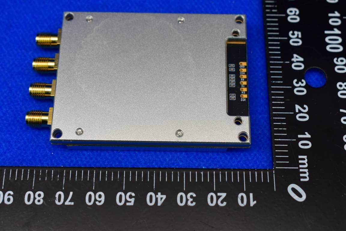
2AC6ACM7104
Dec 14, 2023UHF RFID Module
Equipment Class
DSS - Part 15 Spread Spectrum Transmitter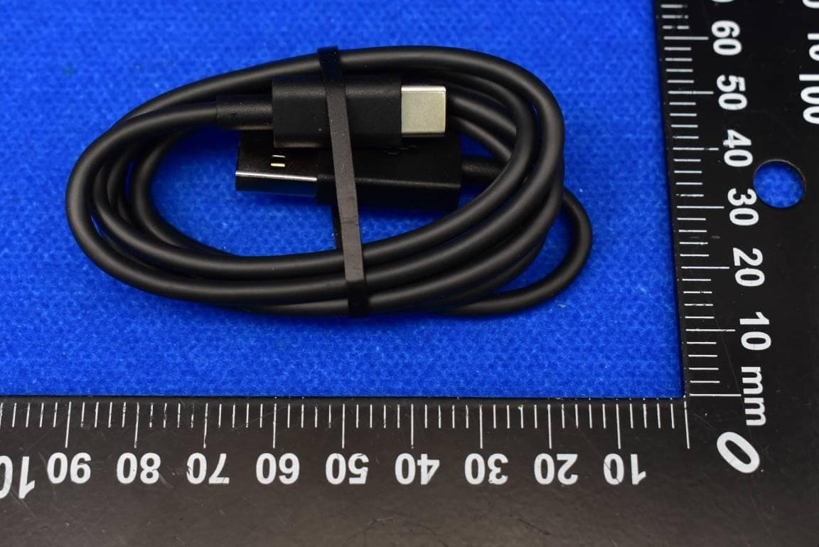
2AC6ASR160
Nov 08, 2023UHF RFID Scanner with Bluetooth
Equipment Class
DSS - Part 15 Spread Spectrum Transmitter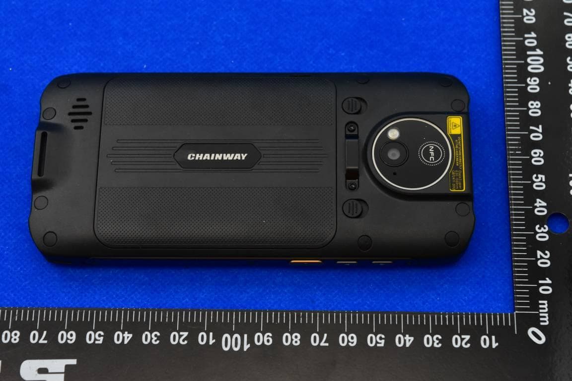
2AC6AMC95
May 04, 2023Mobile Data Terminal with BT, WIFI, GSM, WCDMA, LTE and NFC
Equipment Class
PCE - PCS Licensed Transmitter held to ear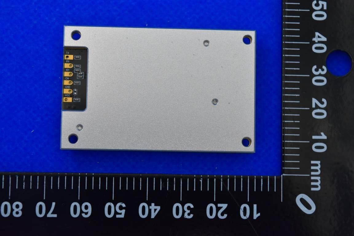
2AC6ACM7101
Apr 18, 2023UHF RFID Module
Equipment Class
DSS - Part 15 Spread Spectrum Transmitter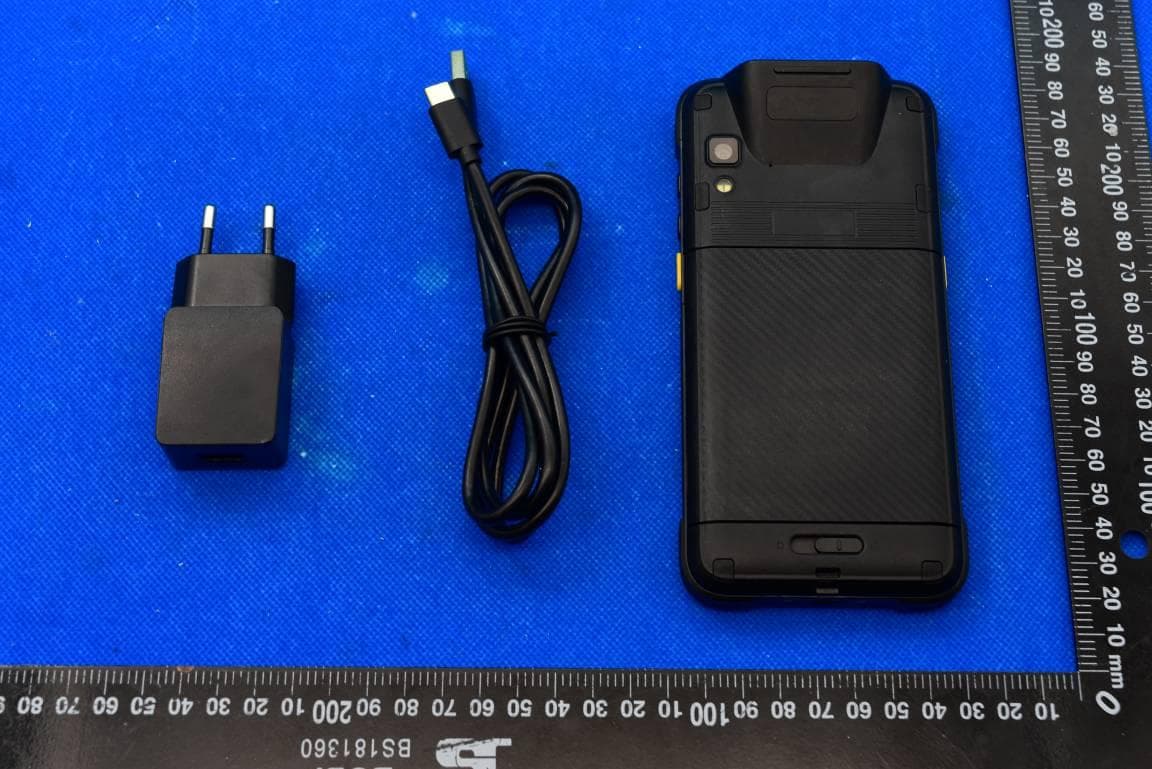
2AC6AC66W
Dec 21, 2022Mobile Data Terminal with BT, WiFi, and RFID
Equipment Class
DSS - Part 15 Spread Spectrum Transmitter