2AC7Z-ESP8266EXWi-Fi Internet of Things Module
ESPRESSIF SYSTEMS (SHANGHAI) CO., LTD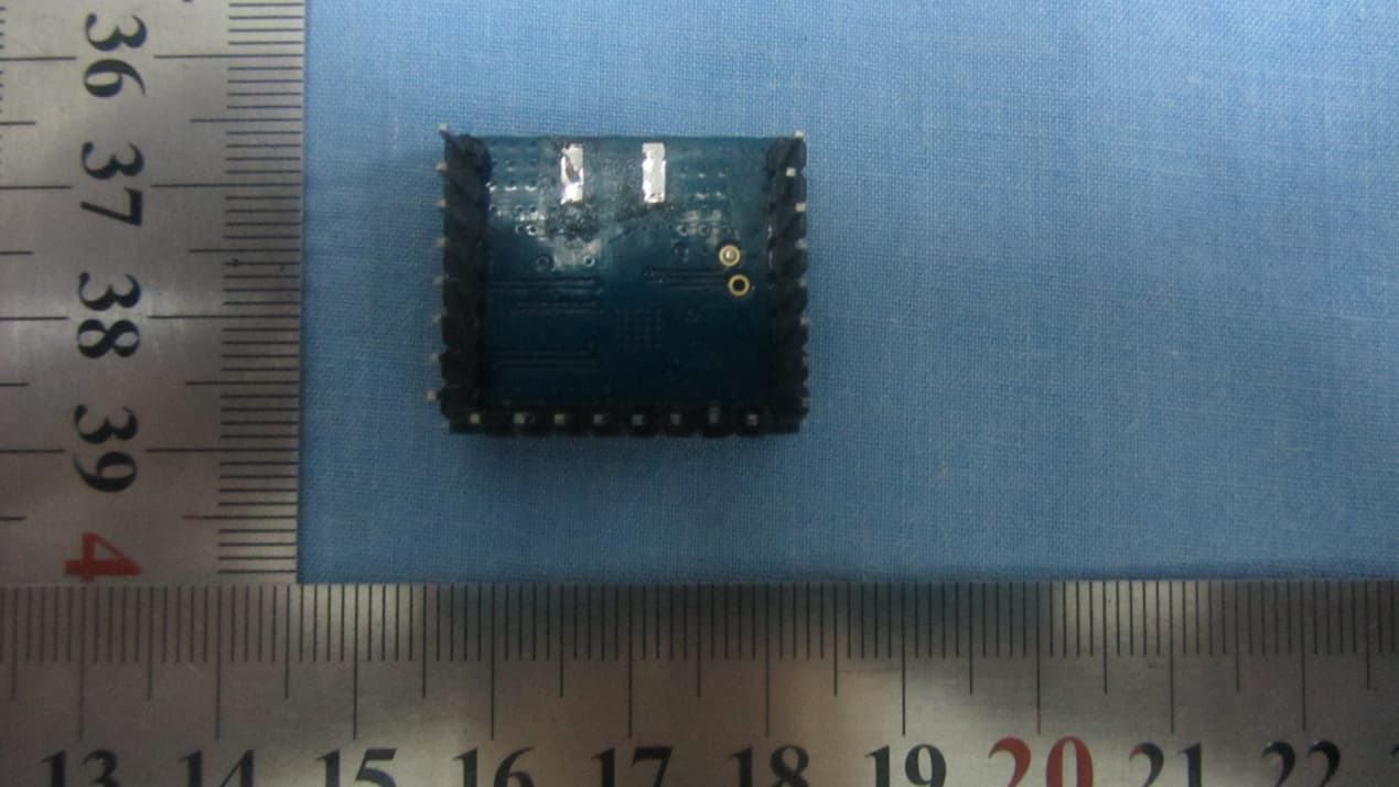
Click to zoom
Application Details
- Equipment Class
- DTS - Digital Transmission System
- Date of Grant
- Nov 04, 2014
- Application Purpose
- Original Equipment
- Date of Application
- Nov 04, 2014
- Equipment Note
- Wi-Fi Internet of Things Module
- Frequency Range
- 2412.00000000 - 2462.00000000
- Country
- China
Documents & Files
Document Text
Text extracted from the exhibit documents filed with the FCC. Open a document above to read the original.
Users Manual
ESP8266User Manual 1 / 12Espressif SystemsJune 19, 2014 ESP8266EX WiFiModule USER MANUAL FOR OEM OR INTEGRATORS ONLY: This module is limited to OEM installation only and must not be sold to end-users. [ ] CONFIDENTIAL [ ] INTERNAL [ ] PUBLIC Disclaimer and Copyright Notice Information in this document, including URL references, is subject to change without notice. THIS DOCUMENT IS PROVIDED "AS IS" WITH NO WARRANTIES WHATSOEVER, INCLUDING ANY WARRANTY OF MERCHANTABILITY, NONINFRINGEMENT, FITNESS FOR ANY PARTICULAR PURPOSE, OR ANY WARRANTY OTHERWISE ARISING OUT OF ANY PROPOSAL, SPECIFICATION OR SAMPLE. All liability, including liability for infringement of any proprietary rights, relating to use of information in this document is disclaimed. No licenses express or implied, by estoppel or otherwise, to any intellectual property rights are granted herein. The Wi-Fi Alliance Member Logo is a trademark of the Wi-Fi Alliance. All trade names, trademarks and registered trademarks mentioned in this document are property of their respective owners, and are hereby acknowledged. Copyright © 2013 Espressif Systems Inc. All rights reserved. Caution: Changes or modifications not expressly approved by the manufacturer could void the user’s authority to operate the equipment. This device complies with part 15 of the FCC Rules. Operation is subject to the following two conditions: (1) This device may not cause harmful interference, and (2) this device must accept any interference received, including interference that may cause undesired operation. ESP8266User Manual 2 / 12Espressif SystemsJune 19, 2014 Table of Contents 2. Table of Contents ....................................................................................................... 2 1. Foreword .................................................................................................................... 3 2. FCC RF exposure requirements ................................................................................. 4 2.1. Standards and Regulatory Compliance ................................................................ 4 2.1.1. Standards and certification .............................................................................. 4 2.1.2. FCC certification requirements ........................................................................ 4 2.1.3. FCC RF exposure requirements ........................................................................ 6 3. Download Tools .......................................................................................................... 8 3.1. XTCOM_UTIL ........................................................................................................ 8 3.2. ESP_FLASH_DOWNLOAD ................................................................................... 11 ESP8266User Manual 3 / 12Espressif SystemsJune 19, 2014 1. Foreword This manual mainly introduces how to use ESP8266‐based SDK for Internet of Things, including virtual machine installation, development tool usage, SDK software development kit etc. OEM integrators must be instructed to ensure that the end‐user has no manual instructions to remove or install the device. The end‐user can not remove or install this module to any other devices. ESP8266User Manual 4 / 12Espressif SystemsJune 19, 2014 2. FCC RF exposure requirements 2.1. Standards and Regulatory Compliance 2.1.1. Standards and certification The EUT conforms to the following standards and certification requirements: 802.11 b/g/n FCC ❒ 47 CFR Part 1 ‐ RF radiation exposure limits ❒ 47 CFR Part 2 ‐ Equipment authorization ❒ 47 CFR Part C ‐ WIFI 2.1.2. FCC certification requirements According to the definition of mobile and fixed device is described in Part 2.1091(b), this device is a mobile device. And the following conditions must be met: 1. The EUT is a mobile device; maintain at least a 20 cm separation between the EUT and the user’s body and must not transmit simultaneously with any other antenna or transmitter. 2. The device is only for fixed operation mode. (A Class II Change would be required for near‐body Host applications.) 3. A label with the following statements must be attached to the host end product: This device contains Tx FCC ID: 2AC7Z‐ESP8266EX. 4. To comply with FCC regulations limiting both maximum RF output power and human exposure to RF radiation, maximum antenna gain (including cable loss) must not exceed: ❒ 802.11b band < 2.0 dBi ❒ 802.11g band <2.0 dBi ESP8266User Manual 5 / 12Espressif SystemsJune 19, 2014 ❒ 802.11n band <2.0 dBi 5. This module must not transmit simultaneously with any other antenna or transmitter 6. The host end product must include a user manual that clearly defines operating requirements and conditions that must be observed to ensure compliance with current FCC RF exposure guidelines. For portable devices, in addition to the conditions 3 through 6 described above, a separate approval is required to satisfy the SAR requirements of FCC Part 2.1093 If the device is used for other equipment that separate approval is required for all other operating configurations, including portable configurations with respect to 2.1093 and different antenna configurations. For this device, OEM integrators must be provided with labeling instructions of finished products. Please refer to KDB784748 D01 v07, section 8. Page 6/7 last two paragraphs: A certified modular has the option to use a permanently affixed label, or an electronic label. For a permanently affixed label, the module must be labelled with an FCC ID ‐ Section 2.926 (see 2.2 Certification (labelling requirements) above). The OEM manual must provide clear instructions explaining to the OEM the labelling requirements, options and OEM user manual instructions that are required (see next paragraph). For a host using a certified modular with a standard fixed label, if (1) the module’s FCC ID is not visible when installed in the host, or (2) if the host is marketed so that end users do not…
Text truncated - open the document above for the full version.
Cover Letter(s)
Request for Confidentiality Date: __2014/10/27______ Subject: Confidentiality Request for: _____2AC7Z-ESP8266EX Pursuant to FCC 47 CRF 0.457(d) and 0.459 and IC RSP-100, Section 10, the applicant requests that a part of the subject FCC application be held confidential. Type of Confidentiality Requested Exhibit Short Term Permanent Block Diagrams Short Term External Photos Short Term Permanent* 1 Internal Photos Short Term Permanent Operation Description/Theory of Operation Short Term Permanent Parts List & Placement/BOM Short Term Permanent Tune-Up Procedure Short Term Permanent Schematics Short Term Test Setup Photos Short Term Permanent* User’s Manual *Note: ______(Insert Explanation as Necessary)______ _____ESPRESSIF SYSTEMS (SHANGHAI) PTE LTD______ has spent substantial effort in developing this product and it is one of the first of its kind in industry. Having the subject information easily available to "competition" would negate the advantage they have achieved by developing this product. Not protecting the details of the design will result in financial hardship. Permanent Confidentiality: The applicant requests the exhibits listed above as permanently confidential be permanently withheld from public review due to materials that contain trade secrets and proprietary information not customarily released to the public. Short-Term Confidentiality: The applicant requests the exhibits selected above as short term confidential be withheld from public view for a period of ___(specify number of days not to exceed 180 ) 2 ___ days from the date of NOTE for Industry Canada Applications: The applicant understands that until such time that IC distinguishes between Short Term and Permanent Confidentiality, either type of marked exhibit above will simply be marked Confidential when submitted to IC. Sincerely, Minjie Cai/Marketing Maneger
Cover Letter(s)
Modular Approval Request Letter FCC ID: 2AC7Z-ESP8266EX Data: October 31, 2014 Gentlemen: There’s an Wi-Fi Internet of Things Module that would like to have your authorization as a modular approval. The specific product as below, Wi-Fi Internet of Things Module, with its designed features and specified description, meets special requirements for full modular approval on FCC Public Notice 15.212 Released: June 26, 2000 by cross-reference list below. Company : ESPRESSIF SYSTEMS (SHANGHAI) PTE LTD Model Name : Wi-Fi Internet of Things Module Model Number : ESP8266EX FCC ID : 2AC7Z-ESP8266EX Requirement of Public Notice 15.212 Reference to ESP8266EX. 1. The modular transmitter must have its own RF shielding. The module has its own RF shielding. Please see external photo.pdf 2. The modular transmitter must have buffered modulation/data inputs. The modular has buffered data inputs, it is integrated in chip ESP8266EX. Please see schematic.pdf 3. The modular transmitter must have its own power supply regulation. All power lines derived from the host device are regulated before energizing other circuits internal to the ESP8266EX. Please see schematic.pdf 4. The modular transmitter must comply with the antenna requirements of Section 15.203 and 15.204(c). The ESP8266EX meets the FCC antenna requirements. Please see external photo.pdf 5. The modular transmitter must be tested in a stand‐alone configuration, i.e., the module must not be inside another device during testing. The ESP8266EX was tested in a stand‐alone configuration via com serial interface. Please see test set‐up photo.pdf 6. The modular transmitter must be labeled with its own FCC ID number, and, if the FCC ID is not visible when the module is installed inside another device, then the outside of the device into which the module is installed must also display a label referring to the enclosed module. The label position of ESP8266EX is clearly indicated. If the FCC ID of the module cannot be seen when it is installed, then the host label must include the text: Contains FCC ID: 2AC7Z‐ESP8266EX. Please see the label.pdf 7. The modular transmitter must comply with any specific rule or operating requirements applicable to the transmitter and the manufacturer must provide adequate instructions along with the module to explain any such requirements. A copy of these instructions must be included in the application for equipment authorization. The ESP8266EX is compliant with all applicable FCC rules. Detail instructions are given in the Users Manual. Please see user manual.pdf 8. The modular transmitter must comply with any applicable RF exposure requirements. For example, FCC Rules in Sections 2.1091, 2.1093 and specific Sections of Part 15, including 15.319(i), 15.407(f), 15.253(f) and 15.255(g), require that Unlicensed PCS, UNII and millimeter wave devices perform routine environmental evaluation for RF Exposure to demonstrate compliance. In addition, spread spectrum transmitters operating under Section 15.247 are required to address RF Exposure compliance in accordance with Section 15.247(b)(4). The ESP8266EX is approved to comply with the applicable RF exposure requirement, please see the MPE evaluation with 20cm as the distance restriction. Thank you. Sincerely, Minjie Cai / Marketing Manager ESPRESSIF SYSTEMS (SHANGHAI) PTE LTD Tel: 86-021- 61062057 [email protected]
External Photos
2AC7Z‐ESP8266EX External Photo
ID Label/Location Info
12mm 13mm
Internal Photos
ESP8266EX Internal Photo
Operational Description
W1030.B (2/14)1 pulseelectronics.com/products/antennas Wireless External Antenna for 2.4 GHz Applications Pulse Part Number W1030 San Diego, CA 858 674 8100 Vancouver, WA 360 944 7551Europe 49 7032 7806 0Asia 86 755 33966678North Asia 886 3 4356768China 86 512 6807 9998 3.248 ± .079 1.015 ± 0.020 25,8 ± 0,5 82,5 ± 2,00 Features -Shortest antennas in product line -For WLAN devices using WiFi (802.11b/g), Bluetooth® and ZigBee TM -Omni-directional radiation pattern provides broad 360° coverage -One-quarter wavelength dipole configuration -Connection options easily integrate with OEM designsck Connector -Reverse SMA (Male)* -SMA (Male) * Default Configuration – Please contact Pulse Applications Engineering for assistance in ordering connectors Weight. . . . . . . . . . . . . . . . . . . . . . . 6.3 grams Carton . . . . . . . . . . . . . . . . . 20/bag, 500/carton Dimensions [in / mm] Unless otherwise specified, all tolerances are ± .010 / 0.25 Part Number Frequency [GHz] Gain [dBi] Impedance [Nom] VSWRPolarization Electrical Length Radiation W10302.4 - 2.52.050 Ω≤2.0Vertical1/4, dipole Omni Electrical Specifications @ 25 ºC Note: This part number is lead-free and RoHS compliant. No additional suffix or identifier is required 2 pulseelectronics.com/products/antennas Wireless External Antenna for 2.4 GHz Applications Pulse Part Number W1030 W1030.B (2/14)2 pulseelectronics.com/products/antennas 2 pulseelectronics.com/products/antennas For More Information Pulse Worldwide Headquarters 12220 World Trade Drive San Diego, CA 92128 U.S.A. Tel: 858 674 8100 Fax: 858 674 8262 Larsen Brand Antennas 3611 NE 112th Avenue Vancouver, WA 98682 USA Tel: 360 944 7551 Fax: 369 944 7556 Europe Headquarters Pulse GmbH & Do, KG Zeppelinstrasse 15 Herrenberg Germany Tel: 49 7032 7806 0 Fax: 49 7032 7806 135 Asia Headquarters B402, Shenzhen Academy of Aerospace Technology Bldg. 10th Kejinan Road, High-Tech Zone Nanshan District, Shenzen, PR China 518057 Tel: 86 755 33966678 Fax: 86 755 33966700 Pulse North Asia 3F, No. 198, Zhongyuan Road Zhongli City, Taoyuan County 320 Taiwan R. O. C. Tel: 886 3 4356768 Fax: 886 3 4356823 Pulse (Suzhou) Wireless Products Co, Inc. 99 Huo Ju Road, (#29 Bldg, 4th Phase) Suzhou New District Science & Tech Industrial Park Jiangsu Province, Suzhou 215009 PR China Tel: 86 512 6807 9998 Fax: 86 512 6809 8023 Performance warranty of products offered on this data sheet is limited to the parameters specified. Data is subject to change without notice. Other brand and product names mentioned herein may be trademarks or registered trademarks of their respective owners. © Copyright, 2014. Pulse Electronics, Inc. All rights reserved. Application Notes Omni-directional antennas provide a uniform, donut- shaped, 360 ̊ radiation pattern. The omni-directional pattern is suitable for point-to-multipoint broadcasting in all directions. The antenna is primarily used for WLAN applications. However, it can also be used for a variety of other applications within the specified frequency range. When used as an access point, the antenna is ideally located at the center of the coverage area. Horizontal Position Gain Performance W1030 Vertical Position
RF Exposure Info
Report No.: RXA1409-0216MPE01 Page 1 of 5 : MPE REPORT Product Name Wi-Fi Internet of Things Module Manufacture ESPRESSIF SYSTEMS (SHANGHAI) PTE LTD Model ESP8266EX FCC ID 2AC7Z-ESP8266EX Date of issue October 21, 2014 Approved by Kai Xu Director Revised by Minbao Ling SAR Manager Performed by Jian Qi SAR Engineer Test By Company: TA Technology (Shanghai) Co., Ltd. Address: No.145, Jintang Rd, Tangzhen Industry Park, Pudong Shanghai,China Contact: Xu Kai Telephone: +86-021-50791141/2/3 Fax: +86-021-50791141/2/3-8000 Website: http://www.ta-shanghai.com E-mail: [email protected] TA Technology (Shanghai)Co.,Ltd. Test Report Report No.: RXA1409-0216MPE01 Page 2 of 5 Maximum Permissible Exposure Type of EUT: Wi-Fi Internet of Things Module FCC ID: 2AC7Z-ESP8266EX Manufacturer: ESPRESSIF SYSTEMS (SHANGHAI) PTE LTD Model: ESP8266EX Maximum conducted output power (measured) and antenna Gain: Band Output Power(dBm) 802.11b 22.49 802.11g 24.25 802.11n(20M) 24.22 According to section 1.1310 of FCC 47 CFR Part 1, limits for maximum permissible exposure (MPE) are as following Band maximum tune up procedure (dBm) Antenna Gain (dBi) 802.11b 23 2 802.11g 25 2 802.11n(20M) 25 2 TA Technology (Shanghai)Co.,Ltd. Test Report Report No.: RXA1409-0216MPE01 Page 3 of 5 Note1. Occupational/controlled limits apply in situations in which persons are exposed as a consequence of their employment provided those persons are fully aware of the potential for exposure and can exercise control over their exposure. Limits for occupational/controlled exposure also apply in situations when an individual is transient through a location where occupational / controlled limits apply provided he or she is made aware of the potential for exposure. Note2: General population/uncontrolled exposures apply in situations in which the general public may be exposed, or in which persons that are exposed as a consequence of their employment may not be fully aware of the potential for exposure or can not exercise control over their exposure. TA Technology (Shanghai)Co.,Ltd. Test Report Report No.: RXA1409-0216MPE01 Page 4 of 5 The maximum permissible exposure for 300~1500MHz is f/1500, 1500~100,000MHz is f/1500.So IMPORTANT NOTE: To comply with the FCC RF exposure compliance requirements, the antenna(s) used for this transmitter must be installed to provide a separation distance of at least 20 cm from all persons and must not be co-located or operating in conjunction with any other antenna or transmitter. No change to the antenna or the device is permitted. Any change to the antenna or the device could result in the device exceeding the RF exposure requirements and void user’s authority to operate the device. Band The maximum permissible exposure 802.11b/g/n 1 mW/cm² TA Technology (Shanghai)Co.,Ltd. Test Report Report No.: RXA1409-0216MPE01 Page 5 of 5 RF Exposure Calculations: The following information provides the minimum separation distance for the highest gain antenna provided. This calculation is based on the conducted power, considering maximum power and antenna gain. The formula shown in KDB 865664 D01 is used in the calculation. Equation from KDB 865664 D01, Edition 97-01 is: S= PG / 4∏R 2 where: S = power density (in appropriate units, e.g. mW/cm 2 ) P = Time-average maximum tune up procedure (in appropriate units, e.g., mW) G = the numeric gain of the antenna R = distance to the center of radiation of the antenna ( 20 cm = limit for MPE) So, the numeric gain (G) of the antenna with a gain specified in dB is determined by Numeric gain (G)=10^(antenna gain/10)=10^(2/10)=1.58 dB 802.11b PG = 23dBm+ (2dBi) =25dBm=316mW 802.11g PG = 25dBm+ (2dBi) =27dBm= 501mW 802.11n(20M) PG = 25dBm+(2dBi)=27dBm= 501mW R =20 cm ∏= 3.1416 Solving for S, the power density at 20 cm is Band Test Result (mW/cm 2 ) Limit Value (mW/cm 2 ) 802.11b 0.06 1 mW/cm² 802.11g 0.10 1 mW/cm² 802.11n(20M) 0.10 1 mW/cm² Note: For mobile or fixed location transmitters, minimum separation distance is 20cm, even if calculations indicate MPE distance is less.
Schematics
C10 C10x1C10x2 C21 C21x1 C21x2 C22 C22x1 C22x2 C28 C28x1 C28x2 C29 C29x1 C29x2 C33 C33x1 C33x2 C34 C34x1 C34x2 C4 C4x1C4x2 C40 C40x1C40x2 C5 C5x1C5x2 C6 C6x1C6x2 C7 C7x1 C7x2 J14 J14x1 J14x2 J14x5 J33 J33x1 J34 J34x1 J35 J35x1 J36 J36x1 J37 J37x1 J38 J38x1 J39 J39x1 J40 J40x1 J41 J41x1 J42 J42x1 J43 J43x1 J44 J44x1 J45 J45x1 J46 J46x1 J47 J47x1 J48 J48x1 J49 J49x1 J50 J50x1 J51 J51x1 J52 J52x1 J53 J53x1 J54 J54x1 J55 J55x1 J56 J56x1 J57 J57x1 J58 J58x1 L1 L1x1 L1x2 L2 L2x1L2x2 L4 L4x1 L4x2 L5 L5x1 L5x2 R17 R17x1 R17x2 R4 R4x1R4x2 U1 U1x1 U1x2 U1x3 U1x4 U1x5 U1x6 U1x7 U1x8 U1x9U1x10U1x11U1x12U1x13U1x14U1x15U1x16 U1x17 U1x18 U1x19 U1x20 U1x21 U1x22 U1x23 U1x24 U1x25U1x26U1x27U1x28U1x29U1x30U1x31U1x32 U1x33 U2 U2x1U2x2 U2x3U2x4 J33 J33x1 J34 J34x1 J35 J35x1 J36 J36x1 J37 J37x1 J38 J38x1 J39 J39x1 J40 J40x1 J41 J41x1 J42 J42x1 J43 J43x1 J44 J44x1 J45 J45x1 J46 J46x1 J47 J47x1 J48 J48x1 J49 J49x1 J50 J50x1 J51 J51x1 J52 J52x1 J53 J53x1 J54 J54x1 J55 J55x1 J56 J56x1 J57 J57x1 J58 J58x1 J33 J33x1 J34 J34x1 J35 J35x1 J36 J36x1 J37 J37x1 J38 J38x1 J39 J39x1 J40 J40x1 J41 J41x1 J42 J42x1 J43 J43x1 J44 J44x1 J45 J45x1 J46 J46x1 J47 J47x1 J48 J48x1 J49 J49x1 J50 J50x1 J51 J51x1 J52 J52x1 J53 J53x1 J54 J54x1 J55 J55x1 J56 J56x1 J57 J57x1 J58 J58x1 J14 J14x3 J14x4 J33 J33x1 J34 J34x1 J35 J35x1 J36 J36x1 J37 J37x1 J38 J38x1 J39 J39x1 J40 J40x1 J41 J41x1 J42 J42x1 J43 J43x1 J44 J44x1 J45 J45x1 J46 J46x1 J47 J47x1 J48 J48x1 J49 J49x1 J50 J50x1 J51 J51x1 J52 J52x1 J53 J53x1 J54 J54x1 J55 J55x1 J56 J56x1 J57 J57x1 J58 J58x1 C10 C21 C22 C28 C29 C33 C34 C4 C40 C5 C6 C7 L1 L2 L4L5 R17 R4 U1 C10 C21 C22 C28 C29 C33C34 C4 C40 C5 C6 C7 J14 L1 L2 L4 L5 R17 R4 PCB ÒªÇóPCB ÒªÇó PCB REQUIREMENT 1. PCB is four layers 2. PCB material is FR-4(er=4.2) 4. The thickness between top layer and the second layer is 8.6miles, 5. the impedance to the 15mil trace is 50ohm 3. Copper thickness : 1.65mils PCB ÒªÇóPCB ÒªÇó CH_PDTMSTDITCKTDOIO2 IO_VDD IO0 D2 D3 CMD CLK D0 D1 RXDTXDLNARSTBPA XPD TOUT 3 4 1 1 1111111 1 1 1 1 1 1 11111 1 1 1 111 12 1 2 1 2 1 2 1 2 1 2 1 2 12 12 12 12 1 2 1 2 5 1 1 1111111 1 1 1 1 1 1 11111 1 1 1 111 1 2 12 1 2 1 2 1 2 12 1 2 3 4 5 6 7 8 9 10111213141516 17 18 19 20 21 22 23 24 2526272829303132 33 12 34 C10 C21 C22 C28 C29 C33 C34 C4 C40 C5 C6 C7 L1 L2 L4L5 R17 R4 U1 C10 C21 C22 C28 C29 C33C34 C4 C40 C5 C6 C7 J14 J33 J33x1 J34 J34x1 J35 J35x1 J36 J36x1 J37 J37x1 J38 J38x1 J39 J39x1 J40 J40x1 J41 J41x1 J42 J42x1 J43 J43x1 J44 J44x1 J45 J45x1 J46 J46x1 J47 J47x1 J48 J48x1 J49 J49x1 J50 J50x1 J51 J51x1 J52 J52x1 J53 J53x1 J54 J54x1 J55 J55x1 J56 J56x1 J57 J57x1 J58 J58x1 L1 L2 L4 L5 R17 R4 C10 C21 C22 C28 C29 C33C34 C4 C40 C5 C6 C7 J14 J33 J33x1 J34 J34x1 J35 J35x1 J36 J36x1 J37 J37x1 J38 J38x1 J39 J39x1 J40 J40x1 J41 J41x1 J42 J42x1 J43 J43x1 J44 J44x1 J45 J45x1 J46 J46x1 J47 J47x1 J48 J48x1 J49 J49x1 J50 J50x1 J51 J51x1 J52 J52x1 J53 J53x1 J54 J54x1 J55 J55x1 J56 J56x1 J57 J57x1 J58 J58x1 L1 L2 L4 L5 R17 R4 C10 C21 C22 C28 C29 C33C34 C4 C40 C5 C6 C7 J14 J33 J33x1 J34 J34x1 J35 J35x1 J36 J36x1 J37 J37x1 J38 J38x1 J39 J39x1 J40 J40x1 J41 J41x1 J42 J42x1 J43 J43x1 J44 J44x1 J45 J45x1 J46 J46x1 J47 J47x1 J48 J48x1 J49 J49x1 J50 J50x1 J51 J51x1 J52 J52x1 J53 J53x1 J54 J54x1 J55 J55x1 J56 J56x1 J57 J57x1 J58 J58x1 L1 L2 L4 L5 R17 R4 C10 C21 C22 C28 C29 C33C34 C4 C40 C5 C6 C7 J14 J33 J33x1 J34 J34x1 J35 J35x1 J36 J36x1 J37 J37x1 J38 J38x1 J39 J39x1 J40 J40x1 J41 J41x1 J42 J42x1 J43 J43x1 J44 J44x1 J45 J45x1 J46 J46x1 J47 J47x1 J48 J48x1 J49 J49x1 J50 J50x1 J51 J51x1 J52 J52x1 J53 J53x1 J54 J54x1 J55 J55x1 J56 J56x1 J57 J57x1 J58 J58x1 L1 L2 L4 L5 R17 R4 C10 C21 C22 C28 C29 C33C34 C4 C40 C5 C6 C7 J14 J33 J33x1 J34 J34x1 J35 J35x1 J36 J36x1 J37 J37x1 J38 J38x1 J39 J39x1 J40 J40x1 J41 J41x1 J42 J42x1 J43 J43x1 J44 J44x1 J45 J45x1 J46 J46x1 J47 J47x1 J48 J48x1 J49 J49x1 J50 J50x1 J51 J51x1 J52 J52x1 J53 J53x1 J54 J54x1 J55 J55x1 J56 J56x1 J57 J57x1 J58 J58x1 L1 L2 L4 L5 R17 R4 C10 C21 C22 C28 C29 C33C34 C4 C40 C5 C6 C7 J14 J33 J33x1 J34 J34x1 J35 J35x1 J36 J36x1 J37 J37x1 J38 J38x1 J39 J39x1 J40 J40x1 J41 J41x1 J42 J42x1 J43 J43x1 J44 J44x1 J45 J45x1 J46 J46x1 J47 J47x1 J48 J48x1 J49 J49x1 J50 J50x1 J51 J51x1 J52 J52x1 J53 J53x1 J54 J54x1 J55 J55x1 J56 J56x1 J57 J57x1 J58 J58x1 L1 L2 L4 L5 R17 R4 C10 C21 C22 C28 C29 C33C34 C4 C40 C5 C6 C7 J14 J33 J33x1 J34 J34x1 J35 J35x1 J36 J36x1 J37 J37x1 J38 J38x1 J39 J39x1 J40 J40x1 J41 J41x1 J42 J42x1 J43 J43x1 J44 J44x1 J45 J45x1 J46 J46x1 J47 J47x1 J48 J48x1 J49 J49x1 J50 J50x1 J51 J51x1 J52 J52x1 J53 J53x1 J54 J54x1 J55 J55x1 J56 J56x1 J57 J57x1 J58 J58x1 L1 L2 L4 L5 R17 R4 C10 C21 C22 C28 C29 C33C34 C4 C40 C5 C6 C7 J14 L1 L2 L4 L5 R17 R4 C10 C21 C22 C28 C29 C33C34 C4 C40 C5 C6 C7 J14 L1 L2 L4 L5 R17 R4 C10 C21 C22 C28 C29 C33C34 C4 C40 C5 C6 C7 J14 J33 J33x1 J34 J34x1 J35 J35x1 J36 J36x1 J37 J37x1 J38 J38x1 J39 J39x1 J40 J40x1 J41 J41x1 J42 J42x1 J43 J43x1 J44 J44x1 J45 J45x1 J46 J46x1 J47 J47x1 J48 J48x1 J49 J49x1 J50 J50x1 J51 J51x1 J52 J52x1 J53 J53x1 J54 J54x1 J55 J55x1 J56 J56x1 J57 J57x1 J58 J58x1 L1 L2 L4 L5 R17 R4 C10 C21 C22 C28 C29 C33C34 C4 C40 C5 C6 C7 J14 J33 J33x1 J34 J34x1 J35 J35x1 J36 J36x1 J37 J37x1 J38 J38x1 J39 J39x1 J40 J40x1 J41 J41x1 J42 J42x1 J43 J43x1 J44 J44x1 J45 J45x1 J46 J46x1 J47 J47x1 J48 J48x1 J49 J49x1 J50 J50x1 J51 J51x1 J52 J52x1 J53 J53x1 J54 J54x1 J55 J55x1 J56 J56x1 J57 J57x1 J58 J58x1 L1 L2 L4 L5 R17 R4 C10 C21 C22 C28 C29 C33C34 C4 C40 C5 C6 C7 J14 J33 J33x1 J34 J34x1 J35 J35x1 J36 J36x1 J37 J37x1 J38 J38x1 J39 J39x1 J40 J40x1 J41 J41x1 J42 J42x1 J43 J43x1 J44 J44x1 J45 J45x1 J46 J46x1 J47 J47x1 J48 J48x1 J49 J49x1 J50 J50x1 J51 J51x1 J52 J52x1 J53 J53x1 J54 J54x1 J55 J55x1 J56 J56x1 J57 J57x1 J58 J58x1 L1 L2 L4 L5 R17 R4 C10 C21 C22 C28 C29 C33C34 C4 C40 C5 C6 C7 J14 J33 J33x1 J34 J34x1 J35 J35x1 J36 J36x1 J37 J37x1 J38 J38x1 J39 J39x1 J40 J40x1 J41 J41x1 J42 J42x1 J43 J43x1 J44 J44x1 J45 J45x1 J46 J46x1 J47 J47x1 J48 J48x1 J49 J49x1 J50 J50x1 J51 J51x1 J52 J52x1 J53 J53x1 J54 J54x1 J55 J55x1 J56 J56x1 J57 J57x1 J58 J58x1 L1 L2 L4 L…
Text truncated - open the document above for the full version.
Test Report
TA Technology (Shanghai) Co., Ltd. Test Report Report No.: RXA1409-0216RF01R1 Page 1of 96 TESTING No. L2264 Part 15C TEST REPORT Product Name Wi-Fi Internet of Things Module Model ESP8266EX Brand Name WROOM FCC ID 2AC7Z-ESP8266EX Applicant ESPRESSIF SYSTEMS (SHANGHAI) PTE LTD Manufacturer ESPRESSIF SYSTEMS (SHANGHAI) PTE LTD Date of issue October 28, 2014 TA Technology (Shanghai) Co., Ltd. TA Technology (Shanghai) Co., Ltd. Test Report Report No.: RXA1409-0216RF01R1 Page 2of 96 GENERAL SUMMARY Reference Standard(s) FCC CFR47 Part 15C (2013) Radio Frequency Devices 15.205 Restricted bands of operation; 15.207 Conducted limits; 15.209 Radiated emission limits; general requirements; 15.247 Operation within the bands 902-928 MHz,2400-2483.5 MHz, and 5725-5850MHz. ANSI C63.4 Methods of Measurement of Radio-Noise Emission from Low-Voltage Electrical and Electronic Equipment in the Range of 9 KHz to 40GHz. (2009) KDB 558074 D01 DTS Meas Guidance v03r01 Guidance for Performing Compliance Measurements on Digital Transmission Systems (DTS) Operating Under §15.247 Conclusion This wireless equipment has been measured in all cases requested by the relevant standards. Test results in Chapter 2 of this test report are below limits specified in the relevant standards. General Judgment: Pass Comment The test result only responds to the measured sample. Approved by Kai Xu Director Revised by Lingling Kang RF Manager Performed by Changxu Wan RF Engineer TA Technology (Shanghai) Co., Ltd. Test Report Report No.: RXA1409-0216RF01R1 Page 3of 96 TABLE OF CONTENT 1. General Information ..................................................................................................................... 4 1.1. Notes of the test report ......................................................................................................... 4 1.2. Testing laboratory ................................................................................................................. 5 1.3. Applicant Information ............................................................................................................ 5 1.4. Manufacturer Information ...................................................................................................... 5 1.5. Information of EUT ................................................................................................................ 6 1.6. Test Date .............................................................................................................................. 6 2. Test Information ........................................................................................................................... 7 2.1. Test Mode ............................................................................................................................. 7 2.2. Summary of test results ........................................................................................................ 8 2.3. Peak Power Output –Conducted ........................................................................................... 9 2.4. Occupied Bandwidth (6dB) ................................................................................................. 11 2.5. Band Edge Compliance ...................................................................................................... 17 2.6. Spurious Radiated Emissions in the restricted band ........................................................... 21 2.7. Power Spectral Density ....................................................................................................... 30 2.8. Spurious RF Conducted Emissions .................................................................................... 36 2.9. Radiates Emission .............................................................................................................. 47 2.10. Conducted Emissions ......................................................................................................... 86 2. Main Test Instruments ................................................................................................................ 93 ANNEX A: EUT Appearance and Test Setup ..................................................................................... 94 A.1 EUT Appearance ................................................................................................................ 94 A.2 Test Setup .......................................................................................................................... 95 TA Technology (Shanghai) Co., Ltd. Test Report Report No.: RXA1409-0216RF01R1 Page 4of 96 1. General Information 1.1. Notes of the test report TA Technology (Shanghai) Co., Ltd. has obtained the accreditation of China National Accreditation Service for Conformity Assessment (CNAS), and accreditation number: L2264. TA Technology (Shanghai) Co., Ltd. has been listed on the US Federal Communications Commission list of test facilities recognized to perform electromagnetic emissions measurements. The site recognition number is 428261. TA Technology (Shanghai) Co., Ltd. has been listed by industry Canada to perform electromagnetic emission measurement. The site recognition number is 8510A. TA Technology (Shanghai) Co., Ltd. guarantees the reliability of the data presented in this test report, which is the results of measurements and tests performed for the items under test on the dat…
Text truncated - open the document above for the full version.
Contact Information
Applicant
Mia Zhou
Test Firm
TA Technology (Shanghai) Co., Ltd.Zhihui Liu
Technical Specifications
| # | Rule Parts | Frequency Range | Power Output |
|---|---|---|---|
| 1 | 15C | 2.41 GHz - 2.46 GHz | 266.00 mW |
Other Applications from ESPRESSIF SYSTEMS (SHANGHAI) CO., LTD
2AC7Z-ESPC5MINI1
May 28, 20262.4G&5G Wi-Fi & Bluetooth & zigbee & Thread IoT Module
Equipment Class
NII - Unlicensed National Information Infrastructure TX
2AC7Z-ESPC61WRM1U
Jan 05, 20262.4G Wi-Fi & BLE Internet of Things Module
Equipment Class
DTS - Digital Transmission System
2AC7Z-ESP868407
Feb 08, 20242.4GHz Wi-Fi & BT IoT Module
Equipment Class
DTS - Digital Transmission System
2AC7Z-ESP8684M1U
Sep 10, 20232.4GHz Wi-Fi & BT IoT Module
Equipment Class
DTS - Digital Transmission System
2AC7Z-ESPC6WROOM1
Sep 05, 20232.4GHz Wi-Fi & BT IoT Module
Equipment Class
DTS - Digital Transmission System