2AC9MADTRAN424RGIndoor GPON HGU
Wuxi MitraStar Technology Co.,Ltd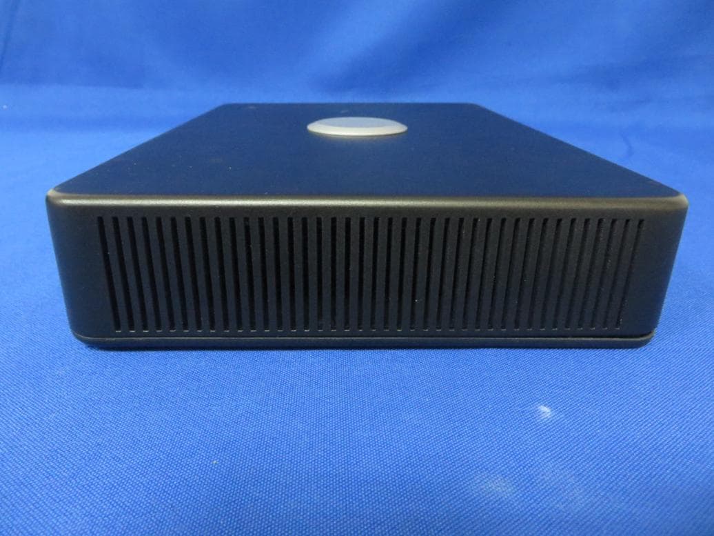
Click to zoom
Application Details
- Equipment Class
- DTS - Digital Transmission System
- Date of Grant
- Mar 22, 2015
- Application Purpose
- Original Equipment
- Date of Application
- Mar 22, 2015
- Equipment Note
- Indoor GPON HGU
- Frequency Range
- 2412.00000000 - 2462.00000000
- Country
- China
Documents & Files
Document Text
Text extracted from the exhibit documents filed with the FCC. Open a document above to read the original.
Users Manual
Adtran 424RG WIFI Dual Band 4 GE LAN GPON HGU Version 1.0 Date 2015.03.10 Copyright@2014 Mitrastar Network Technology Incorporation Quick Installation Guide 1. How to Use the Devices? The device is standing only. As below: 2. Hardware Connections for the 4 models a. Open the PON Cover, connect the fiber cable to the Fiber SC connector of the device. b.Use a Gigabit Ethernet Cable to connect a computer to an Ethernet port for initial configuration and/or internet connection. C. Use the provided UPS or Power Adaptor source to the POWER Socket. Need to push the ON/OFF button to the ON position if Power Adaptor is used. d. Connect the USB dongle to the USB port if USB wants to be used Connectors Sequence (TopDown) – According to PWBA design LED Sequence (TopDown) – According to PWBA design USB Power Reset Button Broadband LAN4 Service LAN3 Wi-Fi 2.4GHz LAN2 Wi-Fi 5GHz LAN1 Ethernet 4 FXS1 Ethernet 3 FXS2 Ethernet 2 Power Jack Ethernet 1 UPS Connector Phone1 Phone2 USB WPS separate LED WPS button 3. Configurations Step1: In your browser, go to http://192.168.1.254, the following screen appears, enter the default username and password: admin/admin and click Login. Step2: After Log into the Web GUI, click Advanced Setup for WAN and LAN configuration. Step 3: Click Connect to Internet, Configure the Connection Type and DNS that ISP assigned. Step 4: Click Configure Wireless Network, Enable the wireless and configure the SSID as you like, the wireless WPA/WPA2 password will be generated automatically. Certifications Federal Communications Commission (FCC) Interference Statement The device complies with Part 15 of FCC rules. Operation is subject to the following two conditions: (1) This device may not cause harmful interference. (2) This device must accept any interference received, including interference that may cause undesired operations. This device has been tested and found to comply with the limits for a Class B digital device pursuant to Part 15 of the FCC Rules. These limits are designed to provide reasonable protection against harmful interference in a residential installation. This device generates, uses, and can radiate radio frequency energy, and if not installed and used in accordance with the instructions, may cause harmful interference to radio communications. However, there is no guarantee that interference will not occur in a particular installation. If this device does cause harmful interference to radio/television reception, which can be determined by turning the device off and on, the user is encouraged to try to correct the interference by one or more of the following measures: • Reorient or relocate the receiving antenna. • Increase the separation between the equipment and the receiver. • Connect the equipment into an outlet on a circuit different from that to which the receiver is connected. • Consult the dealer or an experienced radio/TV technician for help. Radiation Exposure Statement • This device and its antenna(s) must not be co-located or operating in conjunction with any other antenna or transmitter. • For operation within 5.15 ~ 5.25GHz frequency range, it is restricted to indoor environment. • IEEE 802.11b, 802.11g or 802.11n (20MHz) operation of this product in the U.S.A. is firmware-limited to channel 1 through 11. IEEE 802.11n (40MHz) operation of this product in the U.S.A. is firmware-limited to channel 3 through 9. • This equipment complies with FCC radiation exposure limits set forth for an uncontrolled environment. This equipment should be installed and operated with minimum distance 20cm between the radiator and your body. Notices Changes or modifications not expressly approved by the party responsible for compliance could void the user's authority to operate the equipment. The device complies with the essential requirements of the R&TTE Directive 1995/5/EC. Radiation Exposure Statement This equipment complies with EU radiation exposure limits set forth for an uncontrolled environment. This equipment should be installed and operated with minimum distance 20cm between the radiator and your body. National Communications Commission (NCC) Article 12 Without permission, any company, firm or user shall not alter the frequency, increase the power, or change the characteristics and functions of the original design of the certified lower power frequency electric machinery. Article 14 The application of low power frequency electric machineries shall not affect the navigation safety nor interfere a legal communication, if an interference is found, the service will be suspended until improvement is made and the interference no longer exists. Industry Canada (IC) CAN ICES-3 (B)/NMB-3(B) This device complies with RSS-210 of the Industry Canada Rules. Operation is subject to the following two conditions: (1) This device may not cause harmful interference, and (2) this device must accept any interference received, including interference that may cause undesired operation. Cedispositifestconforme à la norme CNR-192 d'Industrie Canada applicable aux appareils radio exempts de licence. Son fonctionnementestsujet aux deux conditions suivantes: (1) ledispositif ne doit pas produire de brouillagepréjudiciable, et (2) cedispositifdoit accepter tout brouillagereçu, y compris un brouillage susceptible de provoquer un fonctionnementindésirable. IMPORTANT NOTE: Radiation Exposure Statement: This equipment complies with IC radiation exposure limits set forth for an uncontrolled environment. This equipment should be installed and operated with minimum distance 20cm between the radiator and your body. Déclarationd'exposition aux radiations: Cetéquipementestconforme aux limitesd'exposition aux rayonnements IC établies pour un environnement non contrôlé. Cetéquipementdoitêtreinstallé et utilisé avec un minimum de 20cm de distance entre la source de rayonnement et votre corps. Safety Warnings . Do NOT use this product near water, for example, in a wet basement or near a swimming pool. . …
Text truncated - open the document above for the full version.
External Photos
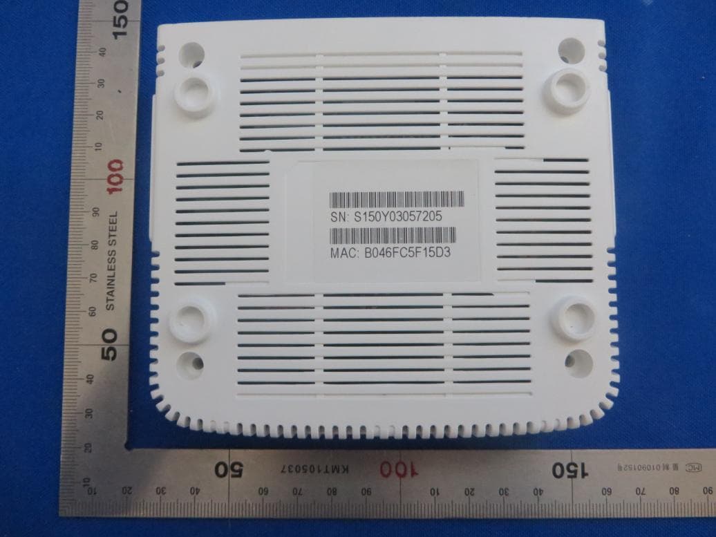
External Photo (1) EUT Photo (2) EUT Photo (3) EUT Photo (4) EUT Photo (5) EUT Photo
Internal Photos
Internal Photo (1) EUT Photo (2) EUT Photo (3) EUT Photo (4) EUT Photo (5) EUT Photo (6) EUT Photo (7) EUT Photo (8) EUT Photo (9) EUT Photo
RF Exposure Info
MRT Technology (Suzhou) Co., Ltd Report No.: 1501RSU00403 Phone: +86-512-66308358 Report Version: V01 Fax: +86-512-66308368 Issue Date: 03-12-2015 Web: www.mrt-cert.com FCC ID: 2AC9MADTRAN424RG Page Number: 1 of 7 RF Exposure Evaluation Declaration FCC ID: 2AC9MADTRAN424RG APPLICANT: Wuxi MitraStar Technology Co., Ltd Application Type: Certification Product: Indoor GPON HGU Model No.: 424RG Trademark: ADTRAN FCC Classification: Digital Transmission System (DTS) Unlicensed National Information Infrastructure (UNII) Reviewed By : ( Robin Wu ) Approved By : ( Marlin Chen ) The test results relate only to the samples tested. The test results shown in the test report are traceable to the national/international standards through the calibration of the equipment and evaluated measurement uncertainty herein. The test report shall not be reproduced except in full without the written approval of MRT Technology (Suzhou) Co., Ltd. Report No.: 1501RSU00403 FCC ID: 2AC9MADTRAN424RG Page Number: 2 of 7 Revision History Report No. Version Description Issue Date 1501RSU00403 Rev. 01 Initial report 03-12-2015 Report No.: 1501RSU00403 FCC ID: 2AC9MADTRAN424RG Page Number: 3 of 7 1. PRODUCT INFORMATION 1.1. Equipment Description Product Name Indoor GPON HGU Model No. 424RG Frequency Range For 2.4GHz Band: 802.11b/g/n-HT20: 2412 ~ 2462MHz 802.11n-HT40: 2422 ~ 2452MHz For 5GHz Band: For 802.11a/n-HT20/ac-VHT20: 5180~5240MHz, 5745~5825MHz For 802.11n-HT40/ac-VHT40: 5190~5230MHz, 5755~5795MHz For 802.11ac-VHT80: 5210MHz, 5775MHz Type of Modulation 802.11b: DSSS 802.11g/a/n/ac: OFDM Maximum Average Output Power For 2.4GHz Band: 802.11b: 23.37dBm 802.11g: 23.35dBm 802.11n-HT20: 26.11dBm 802.11n-HT40: 23.46dBm For 5GHz Band: 802.11a: 27.16dBm 802.11n-HT20: 27.06dBm 802.11n-HT40: 27.04dBm 802.11ac-VHT20: 27.19dBm 802.11ac-VHT40: 27.20dBm 802.11ac-VHT80: 25.01dBm Report No.: 1501RSU00403 FCC ID: 2AC9MADTRAN424RG Page Number: 4 of 7 1.2. Antenna Description Antenna Type Frequency Band (GHz) T X Paths Directional Gain (dBi) PCB Antenna 2.4 2 1.90 Antenn a Type Frequency Band (GHz) T X Paths Directional Gain (dBi) Beam Forming CDD PCB Antenna 5.2 4 8.04 8.04 5.8 4 8.70 8.70 Note: 1. Transmit at 2.4GHz support two antennas, and support four antennas at 5GHz transmit. There are different antenna gains between each antenna. 2. The EUT working on Beam Forming mode, and the Beam Forming support 802.11n/ac, not include 802.11a, and 802.11a working on CDD mode. 3. Correlated signals include, but are not limited to, signals transmitted in any of the following modes: Any transmit Beam Forming mode, whether fixed or adaptive (e.g., phased array modes, closed loop MIMO modes, Transmitter Adaptive Antenna modes, Maximum Ratio Transmission (MRT) modes, and Statistical Eigen Beam Forming (EBF) modes). 4. Unequal antenna gains, with equal transmit powers. For antenna gains given by G 1 , G 2 , ..., G N dBi transmit signals are correlated, then Directional gain = 10 log[(10 G1/20 + 10 G2/20 + ... + 10 GN/20 ) 2 /N ANT ] dBi [Note the “20”s in the denominator of each exponent and the square of the sum of terms; the object is to combine the signal levels coherently.] Report No.: 1501RSU00403 FCC ID: 2AC9MADTRAN424RG Page Number: 5 of 7 2. RF Exposure Evaluation 2.1. Limits According to FCC 1.1310: The criteria listed in the following table shall be used to evaluate the environment impact of human exposure to radio frequency (RF) radiation as specified in 1.1307(b) LIMITS FOR MAXIMUM PERMISSIBLE EXPOSURE (MPE) Frequency Range (MHz) Electric Field Strength (V/m) Magnetic Field Strength (A/m) Power Density (mW/cm 2 ) Average Time (Minutes) (A) Limits for Occupational/ Control Exposures 300-1500 -- -- f/300 6 1500-100,000 -- -- 5 6 (B) Limits for General Population/ Uncontrolled Exposures 300-1500 -- -- f/1500 6 1500-100,000 -- -- 1 30 f= Frequency in MHz Calculation Formula: Pd = (Pout*G)/(4*pi*r2) Where Pd = power density in mW/cm2 Pout = output power to antenna in mW G = gain of antenna in linear scale Pi = 3.1416 r = distance between observation point and center of the radiator in cm Pd is the limit of MPE, 1mW/cm². If we know the maximum gain of the antenna and the total power input to the antenna, through the calculation, we will know the distance r where the MPE limit is reached. Report No.: 1501RSU00403 FCC ID: 2AC9MADTRAN424RG Page Number: 6 of 7 2.2. Test Result of RF Exposure Evaluation Product Indoor GPON HGU Test Item RF Exposure Evaluation Antenna Gain: The maximum Gain measured in fully anechoic chamber is 1.9dBi for 2.4GHz, 8.04dBi for 5.2GHz, and 8.70dBi for 5.8GHz in logarithm scale. For 2.4GHz ISM Band: Test Mode Frequency Band (MHz) Maximum Average Output Power (dBm) Power Density at R = 20 cm (mW/cm 2 ) Limit (mW/cm 2 ) 802.11b 2412 ~ 2462 23.37 0.0669 1 802.11g 2412 ~ 2462 23.35 0.0666 1 802.11n-HT20 2412 ~ 2462 26.11 0.1258 1 802.11n-HT40 2422 ~ 2452 23.46 0.0683 1 For 5GHz UNII Band: Test Mode Frequency Band (MHz) Maximum Average Output Power (dBm) Power Density at R = 20 cm (mW/cm 2 ) Limit (mW/cm 2 ) 802.11a 5180 ~ 5240 23.77 0.0781 1 5745 ~ 5825 27.16 0.7669 1 802.11n-HT20 5180 ~ 5240 23.67 0.2949 1 5745 ~ 5825 27.06 0.7494 1 802.11n-HT40 5190 ~ 5230 24.15 0.3294 1 5755 ~ 5795 27.04 0.7460 1 802.11ac-VHT20 5180 ~ 5240 23.69 0.2963 1 5745 ~ 5825 27.19 0.7722 1 802.11ac-VHT40 5190 ~ 5230 24.03 0.3204 1 5755 ~ 5795 27.20 0.7740 1 802.11ac-VHT80 5210 15.98 0.0502 1 5775 25.01 0.4674 1 Report No.: 1501RSU00403 FCC ID: 2AC9MADTRAN424RG Page Number: 7 of 7 CONCULISON: Both of the WLAN 2.4GHz Band and WLAN 5GHz Band can transmit simultaneously. Therefore, the Max Power Density at R (20 cm) = 0.1258mW/cm 2 + 0.7740mW/cm 2 = 0.8998mW/cm 2 < 1mW/cm 2 . So the EUT complies with the requirement. The End
Test Report
MRT Technology (Suzhou) Co., Ltd Report No.: 1501RSU00401 Phone: +86-512-66308358 Report Version: V01 Fax: +86-512-66308368 Issue Date: 03-12-2015 Web: www.mrt-cert.com FCC ID: 2AC9MADTRAN424RG Page Number: 1 of 240 FCC ID: 2AC9MADTRAN424RG APPLICANT: Wuxi MitraStar Technology Co., Ltd Application Type: Certification Product: Indoor GPON HGU Model No.: 424RG Trademark: ADTRAN FCC Classification: Digital Transmission System (DTS) FCC Rule Part(s): Part 15.247 Test Procedure(s): ANSI C63.10-2013, KDB 558074 D01v03r02, KDB 662911 D01v02r01 Test Date: Jan. 13 ~ Feb. 08, 2015 MEASUREMENT REPORT FCC PART 15.247 WLAN 802.11b/g/n Reviewed By : ( Robin Wu ) Approved By : ( Marlin Chen ) The test results relate only to the samples tested. This equipment has been shown to be capable of compliance with the applicable technical standards as indicated in the measurement report and was tested in accordance with the measurement procedures specified in KDB 558074 D01v03r02. Test results reported herein relate only to the item(s) tested. The test report shall not be reproduced except in full without the written approval of MRT Technology (Suzhou) Co., Ltd. Report No.: 1501RSU00401 FCC ID: 2AC9MADTRAN424RG Page Number: 2 of 240 Revision History Report No. Version Description Issue Date 1501RSU00401 Rev. 01 Initial report 03-12-2015 Report No.: 1501RSU00401 FCC ID: 2AC9MADTRAN424RG Page Number: 3 of 240 CONTENTS Description Page §2.1033 General Information ............................................................................................................ 5 1. INTRODUCTION ........................................................................................................................ 6 1.1. Scope .............................................................................................................................. 6 1.2. MRT Test Location .......................................................................................................... 6 2. PRODUCT INFORMATION ........................................................................................................ 7 2.1. Equipment Description .................................................................................................... 7 2.2. Applicable Standards ...................................................................................................... 8 2.3. Working Frequencies ...................................................................................................... 8 2.4. Description of Available Antennas ................................................................................... 9 2.5. Description of Antenna RF Port ..................................................................................... 10 2.6. Test Mode ..................................................................................................................... 10 2.7. Test Software ................................................................................................................ 11 2.8. Device Capabilities ........................................................................................................ 13 2.9. Test Configuration ......................................................................................................... 13 2.10. EMI Suppression Device(s)/Modifications ..................................................................... 13 2.11. Labeling Requirements ................................................................................................. 13 3. DESCRIPTION of TEST ........................................................................................................... 14 3.1. Evaluation Procedure .................................................................................................... 14 3.2. AC Line Conducted Emissions ...................................................................................... 14 3.3. Radiated Emissions ....................................................................................................... 15 4. ANTENNA REQUIREMENTS .................................................................................................. 16 5. TEST EQUIPMENT CALIBRATION DATE .............................................................................. 17 6. MEASUREMENT UNCERTAINTY ........................................................................................... 18 7. TEST RESULT ......................................................................................................................... 19 7.1. Summary ....................................................................................................................... 19 7.2. 6dB Bandwidth Measurement ....................................................................................... 20 7.2.1. Test Limit ................................................................................................................... 20 7.2.2. Test Procedure used ................................................................................................. 20 7.2.3. Test Setting ................................................................................................................ 20 7.2.4. Test Setup ................................................................................................................. 20 7.2.5. Test Result ................................................................................................................. 21 7.3. Output Power Measurement ......................................................................................... 33 7.3.1. Test Limit ................................................................................................................... 33 Report No.: 1501RSU00401 FCC ID: 2AC9MADTRAN424RG Page Number: 4 of 240 7.3.2. Test Procedure Used ................................................................................................. 33 7.3.3. Test Setting ............................…
Text truncated - open the document above for the full version.
Test Report
Report No.: 1501RSU00401 FCC ID: 2AC9MADTRAN424RG Page Number: 51 of 240 7.5. Conducted Band Edge and Out-of-Band Emissions 7.5.1. Test Limit The limit for out-of-band spurious emissions at the band edge is 30dB below the fundamental emission level, as determined from the in-band power measurement of the DTS channel performed in a 100kHz bandwidth per the PSD procedure. 7.5.2. Test Procedure Used KDB 558074 D01v03r02 - Section 11.2 & Section 11.3 7.5.3. Test Settitng 1. Reference level measurement (a) Set instrument center frequency to DTS channel center frequency (b) Set the span to ≥ 1.5 times the DTS bandwidth (c) Set the RBW = 100 kHz (d) Set the VBW ≥ 3 x RBW (e) Detector = peak (f) Sweep time = auto couple (g) Trace mode = max hold (h) Allow trace to fully stabilize 2. Emission level measurement (a) Set the center frequency and span to encompass frequency range to be measured (b) RBW = 100kHz (c) VBW = 300kHz (d) Detector = Peak (e) Trace mode = max hold (f) Sweep time = auto couple (g) The trace was allowed to stabilize Report No.: 1501RSU00401 FCC ID: 2AC9MADTRAN424RG Page Number: 52 of 240 7.5.4. Test Setup Report No.: 1501RSU00401 FCC ID: 2AC9MADTRAN424RG Page Number: 53 of 240 7.5.5. Test Result Test Mode Data Rate (Mbps) Channel No. Frequency (MHz) Limit Result Ant 0 802.11b 1 01 2412 30dBc Pass 802.11b 1 06 2437 30dBc Pass 802.11b 1 11 2462 30dBc Pass 802.11g 6 01 2412 30dBc Pass 802.11g 6 06 2437 30dBc Pass 802.11g 6 11 2462 30dBc Pass 802.11n-HT20 6.5 01 2412 30dBc Pass 802.11n-HT20 6.5 06 2437 30dBc Pass 802.11n-HT20 6.5 11 2462 30dBc Pass 802.11n-HT40 13.5 03 2422 30dBc Pass 802.11n-HT40 13.5 06 2437 30dBc Pass 802.11n-HT40 13.5 09 2452 30dBc Pass Ant 1 802.11n-HT20 6.5 01 2412 30dBc Pass 802.11n-HT20 6.5 06 2437 30dBc Pass 802.11n-HT20 6.5 11 2462 30dBc Pass 802.11n-HT40 13.5 03 2422 30dBc Pass 802.11n-HT40 13.5 06 2437 30dBc Pass 802.11n-HT40 13.5 09 2452 30dBc Pass Report No.: 1501RSU00401 FCC ID: 2AC9MADTRAN424RG Page Number: 54 of 240 Test Mode Data Rate (Mbps) Channel No. Frequency (MHz) Limit Result Ant 0 / Ant 0 + 1 802.11n-HT20 6.5 01 2412 30dBc Pass 802.11n-HT20 6.5 06 2437 30dBc Pass 802.11n-HT20 6.5 11 2462 30dBc Pass 802.11n-HT40 13.5 03 2422 30dBc Pass 802.11n-HT40 13.5 06 2437 30dBc Pass 802.11n-HT40 13.5 09 2452 30dBc Pass Ant 1 / Ant 0 + 1 802.11n-HT20 6.5 01 2412 30dBc Pass 802.11n-HT20 6.5 06 2437 30dBc Pass 802.11n-HT20 6.5 11 2462 30dBc Pass 802.11n-HT40 13.5 03 2422 30dBc Pass 802.11n-HT40 13.5 06 2437 30dBc Pass 802.11n-HT40 13.5 09 2452 30dBc Pass Report No.: 1501RSU00401 FCC ID: 2AC9MADTRAN424RG Page Number: 55 of 240 802.11b Out-of-Band Emissions - Ant 0 100kHz PSD reference Level Channel 01 (2412MHz) Low Band Edge Spurious Emission Channel 06 (2437MHz) Spurious Emission Report No.: 1501RSU00401 FCC ID: 2AC9MADTRAN424RG Page Number: 56 of 240 Channel 11 (2462MHz) High Band Edge Spurious Emission Report No.: 1501RSU00401 FCC ID: 2AC9MADTRAN424RG Page Number: 57 of 240 802.11g Out-of-Band Emissions - Ant 0 100kHz PSD reference Level Channel 01 (2412MHz) Low Band Edge Spurious Emission Channel 06 (2437MHz) Spurious Emission Report No.: 1501RSU00401 FCC ID: 2AC9MADTRAN424RG Page Number: 58 of 240 Channel 11 (2462MHz) High Band Edge Spurious Emission Report No.: 1501RSU00401 FCC ID: 2AC9MADTRAN424RG Page Number: 59 of 240 802.11n-HT20 Out-of-Band Emissions - Ant 0 100kHz PSD reference Level Channel 01 (2412MHz) Low Band Edge Spurious Emission Channel 06 (2437MHz) Spurious Emission Report No.: 1501RSU00401 FCC ID: 2AC9MADTRAN424RG Page Number: 60 of 240 Channel 11 (2462MHz) High Band Edge Spurious Emission Report No.: 1501RSU00401 FCC ID: 2AC9MADTRAN424RG Page Number: 61 of 240 802.11n-HT40 Out-of-Band Emissions - Ant 0 100kHz PSD reference Level Channel 03 (2422MHz) Low Band Edge Spurious Emission Channel 06 (2437MHz) Spurious Emission Report No.: 1501RSU00401 FCC ID: 2AC9MADTRAN424RG Page Number: 62 of 240 Channel 9 (2452MHz) High Band Edge Spurious Emission Report No.: 1501RSU00401 FCC ID: 2AC9MADTRAN424RG Page Number: 63 of 240 802.11n-HT20 Out-of-Band Emissions - Ant 1 100kHz PSD reference Level Channel 01 (2412MHz) Low Band Edge Spurious Emission Channel 06 (2437MHz) Spurious Emission Report No.: 1501RSU00401 FCC ID: 2AC9MADTRAN424RG Page Number: 64 of 240 Channel 11 (2462MHz) High Band Edge Spurious Emission Report No.: 1501RSU00401 FCC ID: 2AC9MADTRAN424RG Page Number: 65 of 240 802.11n-HT40 Out-of-Band Emissions - Ant 1 100kHz PSD reference Level Channel 03 (2422MHz) Low Band Edge Spurious Emission Channel 06 (2437MHz) Spurious Emission Report No.: 1501RSU00401 FCC ID: 2AC9MADTRAN424RG Page Number: 66 of 240 Channel 9 (2452MHz) High Band Edge Spurious Emission Report No.: 1501RSU00401 FCC ID: 2AC9MADTRAN424RG Page Number: 67 of 240 802.11n-HT20 Out-of-Band Emissions - Ant 0 / Ant 0 + 1 100kHz PSD reference Level Channel 01 (2412MHz) Low Band Edge Spurious Emission Channel 06 (2437MHz) Spurious Emission Report No.: 1501RSU00401 FCC ID: 2AC9MADTRAN424RG Page Number: 68 of 240 Channel 11 (2462MHz) High Band Edge Spurious Emission Report No.: 1501RSU00401 FCC ID: 2AC9MADTRAN424RG Page Number: 69 of 240 802.11n-HT40 Out-of-Band Emissions - Ant 0 / Ant 0 + 1 100kHz PSD reference Level Channel 03 (2422MHz) Low Band Edge Spurious Emission Channel 06 (2437MHz) Spurious Emission Report No.: 1501RSU00401 FCC ID: 2AC9MADTRAN424RG Page Number: 70 of 240 Channel 9 (2452MHz) High Band Edge Spurious Emission Report No.: 1501RSU00401 FCC ID: 2AC9MADTRAN424RG Page Number: 71 of 240 802.11n-HT20 Out-of-Band Emissions - Ant 1 / Ant 0 + 1 100kHz PSD reference Level Channel 01 (2412MHz) Low Band Edge Spurious Emission Channel 06 (2437MHz) Spurious Emission Report No.: 1501RSU00401 FCC ID: 2AC9MADTRAN424RG Page Number: 72 of 240 Channel 11 (2462MHz) High Band Edge Spurious Emission Report No.: 1501RSU00401 FCC ID: 2AC9MADTRAN424RG Page Number: 73 of 240 802.11n-HT40 Out-of-Band Emissions - Ant 1 / Ant 0 + 1 100kHz PSD reference Level Channel 03 (2422MHz) Low Band E…
Text truncated - open the document above for the full version.
Test Report
Report No.: 1501RSU00401 FCC ID: 2AC9MADTRAN424RG Page Number: 101 of 240 Test Mode: 802.11n-HT40 - Ant 0 + 1 Test Site: AC1 Test Channel: 06 Test Engineer: Roy Cheng Remark: 1. Average measurement was not performed if peak level lower than average limit. 2. Other frequency was 20dB below limit line within 1-18GHz, there is not show in the report. Mark Frequency (MHz) Reading Level (dBμV) Factor (dB) Measure Level (dBμV/m) Limit (dBμV/m) Margin (dB) Detector Polarization 3757.0 38.0 -0.4 37.6 74.0 -36.4 Peak Horizontal 4821.5 36.2 2.7 38.9 74.0 -35.1 Peak Horizontal * 6431.5 40.2 5.6 45.8 85.3 -39.5 Peak Horizontal * 8652.5 35.5 8.8 44.3 85.3 -41.0 Peak Horizontal 3762.7 37.6 -0.3 37.3 74.0 -36.7 Peak Vertical 4876.0 41.5 2.7 44.2 74.0 -29.8 Peak Vertical * 6431.5 39.7 5.6 45.3 85.3 -40.0 Peak Vertical * 8952.3 34.7 9.0 43.7 85.3 -41.6 Peak Vertical Note 1: “*” is not in restricted band, its limit is 20dBc of the fundamental emission level (105.3dBμV/m). Note 2: Measure Level (dBμV/m) = Reading Level (dBμV) + Factor (dB) Factor (dB) = Cable Loss (dB) + Antenna Factor (dB/m) - Pre_Amplifier Gain (dB) Report No.: 1501RSU00401 FCC ID: 2AC9MADTRAN424RG Page Number: 102 of 240 Test Mode: 802.11n-HT40 - Ant 0 + 1 Test Site: AC1 Test Channel: 09 Test Engineer: Roy Cheng Remark: 1. Average measurement was not performed if peak level lower than average limit. 2. Other frequency was 20dB below limit line within 1-18GHz, there is not show in the report. Mark Frequency (MHz) Reading Level (dBμV) Factor (dB) Measure Level (dBμV/m) Limit (dBμV/m) Margin (dB) Detector Polarization 3756.7 38.4 -0.4 38.0 74.0 -36.0 Peak Horizontal 4825.4 35.8 2.7 38.5 74.0 -35.5 Peak Horizontal * 6431.5 40.6 5.6 46.2 86.4 -40.2 Peak Horizontal * 8652.4 35.5 8.8 44.3 86.4 -42.1 Peak Horizontal 3756.4 37.9 -0.4 37.5 74.0 -36.5 Peak Vertical 4910.0 41.1 2.7 43.8 74.0 -30.2 Peak Vertical * 6431.5 39.9 5.6 45.5 86.4 -40.9 Peak Vertical * 7995.5 37.6 8.7 46.3 86.4 -40.1 Peak Vertical Note 1: “*” is not in restricted band, its limit is 20dBc of the fundamental emission level (106.4dBμV/m). Note 2: Measure Level (dBμV/m) = Reading Level (dBμV) + Factor (dB) Factor (dB) = Cable Loss (dB) + Antenna Factor (dB/m) - Pre_Amplifier Gain (dB) Report No.: 1501RSU00401 FCC ID: 2AC9MADTRAN424RG Page Number: 103 of 240 The worst case of Radiated Emission below 1GHz: Site: AC1 Time: 2015/02/05 - 09:32 Limit: FCC_Part15.209_RE(3m) Engineer: Roy Cheng Probe: VULB9162_0.03-8GHz Polarity: Horizontal EUT: Indoor GPON HGU Power: AC 120V/60Hz Note: There is the worst case within frequency range 30MHz~1GHz. No Flag Mark Frequency (MHz) Measure Level (dBuV/m) Reading Level (dBuV) Over Limit (dB) Limit (dBuV/m) Factor (dB) Type 1 179.259 29.755 19.214 -13.745 43.500 10.541 QP 2 250.021 36.400 23.120 -9.600 46.000 13.279 QP 3 375.020 41.942 26.210 -4.058 46.000 15.732 QP 4 625.021 38.357 18.635 -7.643 46.000 19.722 QP 5 * 640.010 42.772 22.895 -3.228 46.000 19.877 QP 6 875.030 34.347 11.210 -11.653 46.000 23.138 QP Note: Measure Level (dBμV/m) = Reading Level (dBμV) + Factor (dB) Factor (dB) = Cable Loss (dB) + Antenna Factor (dB/m) Report No.: 1501RSU00401 FCC ID: 2AC9MADTRAN424RG Page Number: 104 of 240 Site: AC1 Time: 2015/02/05 - 09:32 Limit: FCC_Part15.209_RE(3m) Engineer: Roy Cheng Probe: VULB9162_0.03-8GHz Polarity: Vertical EUT: Indoor GPON HGU Power: AC 120V/60Hz Note: There is the worst case within frequency range 30MHz~1GHz. No Flag Mark Frequency (MHz) Measure Level (dBuV/m) Reading Level (dBuV) Over Limit (dB) Limit (dBuV/m) Factor (dB) Type 1 48.910 32.455 17.680 -7.545 40.000 14.774 QP 2 250.140 36.306 23.023 -9.694 46.000 13.283 QP 3 375.010 38.294 22.562 -7.706 46.000 15.732 QP 4 * 625.032 39.763 20.041 -6.237 46.000 19.722 QP 5 640.021 36.457 16.580 -9.543 46.000 19.877 QP 6 875.010 37.239 14.102 -8.761 46.000 23.137 QP Note: Measure Level (dBμV/m) = Reading Level (dBμV) + Factor (dB) Factor (dB) = Cable Loss (dB) + Antenna Factor (dB/m) Report No.: 1501RSU00401 FCC ID: 2AC9MADTRAN424RG Page Number: 105 of 240 Site: AC1 Time: 2015/02/05 - 09:44 Limit: FCC_Part15.209_RE(3m) Engineer: Roy Cheng Probe: FMZB1519_0.009-30MHz Polarity: Face on EUT: Indoor GPON HGU Power: AC 120V/60Hz Note: There is the ambient noise within frequency range 9kHz~30MHz. No Flag Mark Frequency (MHz) Measure Level (dBuV/m) Reading Level (dBuV) Over Limit (dB) Limit (dBuV/m) Factor (dB) Type 1 0.029 56.893 35.844 -61.463 118.356 21.049 QP 2 * 0.061 52.853 32.542 -59.045 111.898 20.311 QP Note: Measure Level (dBμV/m) = Reading Level (dBμV) + Factor (dB) Factor (dB) = Cable Loss (dB) + Antenna Factor (dB/m) Report No.: 1501RSU00401 FCC ID: 2AC9MADTRAN424RG Page Number: 106 of 240 Site: AC1 Time: 2015/02/05 - 09:44 Limit: FCC_Part15.209_RE(3m) Engineer: Roy Cheng Probe: FMZB1519_0.009-30MHz Polarity: Face on EUT: Indoor GPON HGU Power: AC 120V/60Hz Note: There is the ambient noise within frequency range 9kHz~30MHz. No Flag Mark Frequency (MHz) Measure Level (dBuV/m) Reading Level (dBuV) Over Limit (dB) Limit (dBuV/m) Factor (dB) Type 1 0.502 34.370 13.947 -39.220 73.590 20.423 QP 2 * 1.334 31.595 11.104 -33.530 65.125 20.491 QP Note: Measure Level (dBμV/m) = Reading Level (dBμV) + Factor (dB) Factor (dB) = Cable Loss (dB) + Antenna Factor (dB/m) Report No.: 1501RSU00401 FCC ID: 2AC9MADTRAN424RG Page Number: 107 of 240 Site: AC1 Time: 2015/02/05 - 10:21 Limit: FCC_Part15.209_RE(1m) Engineer: Roy Cheng Probe: BBHA9170_18-40GHz Polarity: Horizontal EUT: Indoor GPON HGU Power: AC 120V/60Hz Note: There is the ambient noise within frequency range 18GHz~25GHz. No Flag Mark Frequency (MHz) Measure Level (dBuV/m) Reading Level (dBuV) Over Limit (dB) Limit (dBuV/m) Factor (dB) Type 1 23943.000 49.776 35.866 -33.724 83.500 13.910 PK 2 * 24741.000 52.375 37.681 -31.125 83.500 14.694 PK Note: Measure Level (dBμV/m) = Reading Level (dBμV) + Factor (dB) Factor (dB) = Cable Loss (dB) + Antenna Factor (dB/m) - Pre_Amplifier Gain (dB) Report No.: 1501RSU00401 FCC ID: 2AC9MADTRAN42…
Text truncated - open the document above for the full version.
Contact Information
Applicant
Kobe Ma(Manager)
Technical Contact
MRT Technology (Suzhou) Co., LtdRobin Wu
[email protected]86-512-66308358
D8 Building, Youxin Industrial Park, No.2 · Suzhou · China
Non-Technical Contact
MRT Technology (Suzhou) Co., LtdRobin Wu
[email protected]86-512-66308358
Test Firm
MRT Technology (Suzhou) Co., LtdWu Jian
[email protected]86-512-66308358
Technical Specifications
| # | Rule Parts | Frequency Range | Power Output |
|---|---|---|---|
| 1 | 15C | 2.41 GHz - 2.46 GHz | 408.30 mW |
Other Applications from Wuxi MitraStar Technology Co.,Ltd
2AC9MDSL100FNT1V2
May 18, 2015Modem BHS MINI Mitrastar
Equipment Class
DTS - Digital Transmission System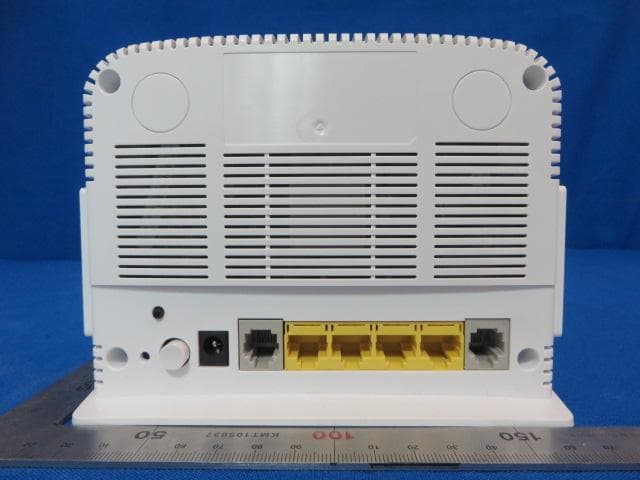
2AC9MDSL2401HNT1C
Apr 22, 2015BHS VDSL VoIP
Equipment Class
DTS - Digital Transmission System