2ACF3BUZZILIGHTBuzzi Light
Blackloud Inc.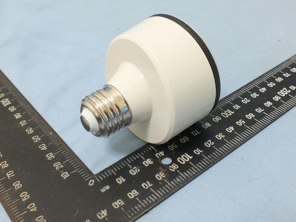
Click to zoom
Application Details
- Equipment Class
- DTS - Digital Transmission System
- Date of Grant
- Oct 22, 2015
- Application Purpose
- Original Equipment
- Date of Application
- Oct 21, 2015
- Equipment Note
- Buzzi Light
- Frequency Range
- 2402.00000000 - 2480.00000000
- Company
- Blackloud Inc.
- Country
- United States
Documents & Files
Document Text
Text extracted from the exhibit documents filed with the FCC. Open a document above to read the original.
Users Manual
Quick Guide - 2Quick Guide - 3Quick Guide - 4Quick Guide - 5Quick Guide - 6Quick Guide - 7Quick Guide - 8 BUZZI LIGHT BUZZI LIGHT Package Contents Top/Side View Setting Up the BUZZI LightGetting Connected Buzzi Light holder This quick guide BUZZI LIGHT BUZZI LIGHT Hardware Setup 1 Make sure the light is unplugged or the power switch is turned off on the light. 2 Insert the BUZZI Light into a standard E26 light socket. Insert a lightbulb into the socket of the BUZZI Light. 3 Plug the light into a power source or turn on the power switch of the light. 4 The lightbulb will not light up until proper set up of the BUZZI app and Internet connection is configured. Note: The BUZZI Light is designed for indoor lighting only. Installing and Launching the BUZZI App 1 On your mobile device, download and install the BUZZI app from either the Google Play Store or the iOS App Store. 2 Make sure that WiFi is enabled on your mobile device, then launch the BUZZI app. 3 If no account settings can be found, the message Sign in fail will appear. You will now have the option to sign in with a BLACKLOUD account, or create an account. Signing In with a BLACKLOUD Account 1 At the BUZZI app Sign In menu, tap Sign in. 2 If you already have a BLACKLOUD account, you can skip the BLACKLOUD account creation and go to step (5). If you do not have a BLACKLOUD account, tap Create New Account. 3 Enter the registration information in the fields indicated, then tap Register. An account confirmation email will be sent to your email address. Confirm the registration in the email. In the app tap to return to the main menu. 4 Once you have a registered BLACKLOUD account, at the BUZZI app’s main menu tap Sign in. Enter your username and password. Your BLACKLOUD account information will appear in the Sign In menu. Connecting to the BUZZI Light There are three ways to connect the BUZZI app to the BUZZI Light: 1 Setup by WiFi: Use a WiFi connection to connect to the BUZZI light. 2 Setup by Bluetooth (for iOS devices only): Use a Bluetooth connection to connect to the BUZZI light. 3 Copy configuration from other device: Use existing settings from other BUZZI electronics to enable the light. NOTE: You can tap on the main menu to access this setup page. Connecting via Bluetooth (for iOS Devices Only) 1 Tap Setup by Bluetooth on the Add BUZZI screen. Follow the on-screen instructions to configure BUZZI Light via Bluetooth. Connecting via WIFI 1 Tap Setup by WiFi on the Add BUZZI screen. Follow the onscreen instructions to configure BUZZI Light via WiFi. 2 For iOS devices only: Locate the BUZZI Light in your iOS device’s WiFi settings and connect to it. Return to the BUZZI app. 3 The app will now connect to the BUZZI Light. Quick Guide - 9Quick Guide - 10Quick Guide - 11Quick Guide - 12Quick Guide - 13Quick Guide - 14Quick Guide - 15Quick Guide - 16 Additional information Federal Communication Commission Interference Statement This equipment has been tested and found to comply with the limits for a Class B digital device, pursuant to Part 15 of the FCC Rules. These limits are designed to provide reasonable protection against harmful interference in a residential installation. This equipment generates, uses and can radiate radio frequency energy and, if not installed and used in accordance with the instructions, may cause harmful interference to radio communications. However, there is no guarantee that interference will not occur in a particular installation. If this equipment does cause harmful interference to radio or television reception, which can be determined by turning the equipment off and on, the user is encouraged to try to correct the interference by one or more of the following measures: Reorient or relocate the receiving antenna. Increase the separation between the equipment and receiver. Connect the equipment into an outlet on a circuit different from that to which the receiver is connected. Consult the dealer or an experienced radio/TV technician for help. FCC Caution: Any changes or modifications not expressly approved by the party responsible for compliance could void the user’s authority to operate this equipment. This device complies with Part 15 of the FCC Rules. Operation is subject to the following two conditions: (1) This device may not cause harmful interference, and (2) this device must accept any interference received, including interference that may cause undesired operation. This device and its antenna(s) must not be co-located or operating in conjunction with any other antenna or transmitter. IMPORTANT NOTE: FCC Radiation Exposure Statement: This equipment complies with FCC radiation exposure limits set forth for an uncontrolled environment. This equipment should be installed and operated with minimum distance 20cm between the radiator & your body. Country Code selection feature to be disabled for products marketed to the US/CANADA Trademarks and trade names are those of their respective owners. Android is a trademark of Google Inc. iOS is a trademark or registered trademark of Cisco in the U.S. and other countries and is used under license. BLACKLOUD® 42 Corporate Park #250 Irvine, CA 92606 USA 888-783-0378 [email protected] www.blackloud.com Connecting via Other Device 1 Tap Copy Configuration from other device on the Add BUZZI screen. Follow the onscreen instructions to configure BUZZI Light via other device settings. 2 Select the BLACKLOUD device you want to copy the connection settings from and tap Okay. Connecting the BUZZI Light to the Internet 1 WiFi Connection a. Have an internet-enabled WiFi AP within range. This access point will be the wireless communication bridge between your mobile device and your BUZZI Light. b. Follow the instructions on the BUZZI app to connect your BUZZI Light to the WiFi AP mentioned above. Testing Your BUZZI Light Once the BUZZI Light is successfully connected to the BUZZI app, the BUZZI Light will appear on the home screen. 1 Tap the power button to t…
Text truncated - open the document above for the full version.
External Photos
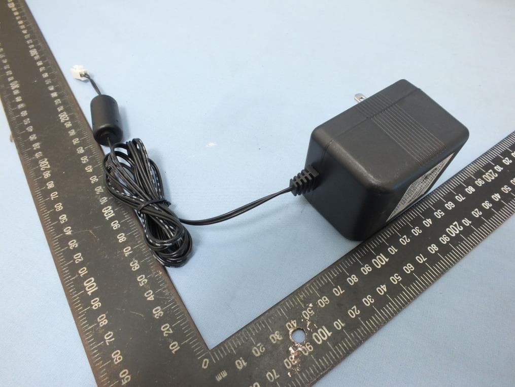
Project No.: EP582901 Page No. : 1 of 6 Photographs of EUT
ID Label/Location Info
BUZZI LIGHT BLACKLOUD INC. Input: 120Vac MAX: 100W Made in Taiwan FCC ID:2ACF3BUZZILIGHT 原檔outlined
Internal Photos
Project No.: EP582901 Page No. : 2 of 6 Project No.: EP582901 Page No. : 3 of 6 Project No.: EP582901 Page No. : 4 of 6 Project No.: EP582901 Page No. : 5 of 6 Project No.: EP582901 Page No. : 6 of 6
Test Report
Report No.: FR582901AE Page : 1 of 33 Report Version: Rev. 01 FCC Test Report FCC ID : 2ACF3BUZZILIGHT Equipment : Buzzi Light Model No. : Buzzi Light Brand Name : Blackloud Inc. Applicant : Blackloud Inc. Address : 42 Corporate Park #250 Irvine, CA 92606 USA Standard : 47 CFR FCC Part 15.247 Received Date : Aug. 29, 2015 Tested Date : Sep. 04 ~ Sep. 21, 2015 We, International Certification Corp., would like to declare that the tested sample has been evaluated and in compliance with the requirement of the above standards. The test results contained in this report refer exclusively to the product. It may be duplicated completely for legal use with the approval of the applicant. It shall not be reproduced except in full without the written approval of our laboratory. Approved & Reviewed by: Gary Chang / Manager Ty: XXX Report No.: FR582901AE Page : 2 of 33 Report Version: Rev. 01 Table of Contents 1 GENERAL DESCRIPTION .................................................................................................................... 5 1.1 Information .............................................................................................................................................. 5 1.2 Local Support Equipment List ................................................................................................................ 7 1.3 Test Setup Chart .................................................................................................................................... 7 1.4 Test Equipment List and Calibration Data .............................................................................................. 8 1.5 Test Standards ....................................................................................................................................... 9 1.6 Measurement Uncertainty ...................................................................................................................... 9 2 TEST CONFIGURATION ..................................................................................................................... 10 2.1 Testing Condition ................................................................................................................................. 10 2.2 The Worst Test Modes and Channel Details ....................................................................................... 10 3 TRANSMITTER TEST RESULTS ........................................................................................................ 11 3.1 Conducted Emissions ........................................................................................................................... 11 3.2 6dB and Occupied Bandwidth .............................................................................................................. 14 3.3 RF Output Power .................................................................................................................................. 16 3.4 Power Spectral Density ........................................................................................................................ 18 3.5 Emissions in Restricted Frequency Bands ........................................................................................... 20 3.6 Emissions in non-restricted Frequency Bands ..................................................................................... 30 4 TEST LABORATORY INFORMATION ............................................................................................... 33 Report No.: FR582901AE Page : 3 of 33 Report Version: Rev. 01 Release Record Report No. Version Description Issued Date FR582901AE Rev. 01 Initial issue Oct. 15, 2015 Report No.: FR582901AE Page : 4 of 33 Report Version: Rev. 01 Summary of Test Results FCC Rules Test Items Measured Result 15.207 AC Power Line Conducted Emissions [dBuV]: 1.452MHz 36.85 (Margin -9.15dB) - AV Pass 15.247(d) 15.209 Radiated Emissions [dBuV/m at 3m]: 37.76MHz 38.99 (Margin -1.01dB) - QP Pass 15.247(b)(3) Maximum Output Power Power [dBm]: 9.87 Pass 15.247(a)(2) 6dB Bandwidth Meet the requirement of limit Pass 15.247(e) Power Spectral Density Meet the requirement of limit Pass 15.203 Antenna Requirement Meet the requirement of limit Pass Report No.: FR582901AE Page : 5 of 33 Report Version: Rev. 01 1 General Description 1.1 Information 1.1.1 Specification of the Equipment under Test (EUT) RF General Information Frequency Range (MHz) Bluetooth Mode Ch. Freq. (MHz) Channel Number Data Rate 2400-2483.5 V4.0 LE 2402-2480 0-39 [40] 1 Mbps Note 1: Bluetooth LE (Low energy) uses GFSK modulation. 1.1.2 Antenna Details Ant. No. Type Connector Gain (dBi) Remarks 1 PIFA N/A 1 --- 1.1.3 Power Supply Type of Equipment under Test (EUT) Power Supply Type 100-120Vac 1.1.4 Accessories N/A Report No.: FR582901AE Page : 6 of 33 Report Version: Rev. 01 1.1.5 Channel List Frequency band (MHz) 2400~2483.5 Channel Frequency (MHz) Channel Frequency (MHz) Channel Frequency (MHz) Channel Frequency (MHz) 37 2402 9 2422 18 2442 28 2462 0 2404 10 2424 19 2444 29 2464 1 2406 38 2426 20 2446 30 2466 2 2408 11 2428 21 2448 31 2468 3 2410 12 2430 22 2450 32 2470 4 2412 13 2432 23 2452 33 2472 5 2414 14 2434 24 2454 34 2474 6 2416 15 2436 25 2456 35 2476 7 2418 16 2438 26 2458 36 2478 8 2420 17 2440 27 2460 39 2480 1.1.6 Test Tool and Duty Cycle Test tool uEngergy Tools, v.2.4.2 Duty cycle of test signal (%) 65.44% Duty Factor (dB) 1.84 1.1.7 Power Setting Modulation Mode Test Frequency (MHz) 2402 2440 2480 GFSK/1Mbps 7 7 7 Report No.: FR582901AE Page : 7 of 33 Report Version: Rev. 01 1.2 Local Support Equipment List Support Equipment List No. Equipment Brand Model FCC ID Signal cable / Length (m) 1 Light bulb tfc PS75(200W) --- --- 2 Lamp load ICC --- --- AC cable, 0.5m non-shielded. 1.3 Test Setup Chart Test Setup Diagram Report No.: FR582901AE Page : 8 of 33 Report Version: Rev. 01 1.4 Test Equipment List and Calibration Data Test Item Conducted Emission Test Site Conductio…
Text truncated - open the document above for the full version.
Test Report
Report No.: FR582901AC Page : 1 of 62 Report Version: Rev. 01 FCC Test Report FCC ID : 2ACF3BUZZILIGHT Equipment : Buzzi Light Model No. : Buzzi Light Brand Name : Blackloud Inc. Applicant : Blackloud Inc. Address : 42 Corporate Park #250 Irvine, CA 92606 USA Standard : 47 CFR FCC Part 15.247 Received Date : Aug. 29, 2015 Tested Date : Sep. 02 ~ Sep. 21, 2015 We, International Certification Corp., would like to declare that the tested sample has been evaluated and in compliance with the requirement of the above standards. The test results contained in this report refer exclusively to the product. It may be duplicated completely for legal use with the approval of the applicant. It shall not be reproduced except in full without the written approval of our laboratory. Approved & Reviewed by: Gary Chang / Manager Ty: XXX Report No.: FR582901AC Page : 2 of 62 Report Version: Rev. 01 Table of Contents 1 GENERAL DESCRIPTION .................................................................................................................... 5 1.1 Information .............................................................................................................................................. 5 1.2 Local Support Equipment List ................................................................................................................ 7 1.3 Test Setup Chart .................................................................................................................................... 7 1.4 The Equipment List ................................................................................................................................ 8 1.5 Test Standards ....................................................................................................................................... 9 1.6 Measurement Uncertainty ...................................................................................................................... 9 2 TEST CONFIGURATION ..................................................................................................................... 10 2.1 Testing Condition ................................................................................................................................. 10 2.2 The Worst Test Modes and Channel Details ....................................................................................... 10 3 TRANSMITTER TEST RESULTS ........................................................................................................ 11 3.1 Conducted Emissions ........................................................................................................................... 11 3.2 6dB and Occupied Bandwidth .............................................................................................................. 14 3.3 RF Output Power .................................................................................................................................. 17 3.4 Power Spectral Density ........................................................................................................................ 19 3.5 Unwanted Emissions into Restricted Frequency Bands ...................................................................... 21 3.6 Emissions in Non-Restricted Frequency Bands ................................................................................... 49 4 TEST LABORATORY INFORMATION ............................................................................................... 62 Report No.: FR582901AC Page : 3 of 62 Report Version: Rev. 01 Release Record Report No. Version Description Issued Date FR582901AC Rev. 01 Initial issue Oct. 15, 2015 Report No.: FR582901AC Page : 4 of 62 Report Version: Rev. 01 Summary of Test Results FCC Rules Test Items Measured Result 15.207 Conducted Emissions [dBuV]: 1.450MHz 36.88 (Margin -9.12dB) - AV Pass 15.247(d) 15.209 Radiated Emissions [dBuV/m at 3m]: 2483.50MHz 52.95 (Margin -1.05dB) - AV Pass 15.247(b)(3) Maximum Output Power Max Power [dBm]: 25.95 Pass 15.247(a)(2) 6dB Bandwidth Meet the requirement of limit Pass 15.247(e) Power Spectral Density Meet the requirement of limit Pass 15.203 Antenna Requirement Meet the requirement of limit Pass Report No.: FR582901AC Page : 5 of 62 Report Version: Rev. 01 1 General Description 1.1 Information 1.1.1 Specification of the Equipment under Test (EUT) RF General Information Frequency Range (MHz) IEEE Std. 802.11 Ch. Freq. (MHz) Channel Number Transmit Chains (N TX ) Data Rate / MCS 2400-2483.5 b 2412-2462 1-11 [11] 1 1-11 Mbps 2400-2483.5 g 2412-2462 1-11 [11] 1 6-54 Mbps 2400-2483.5 n (HT20) 2412-2462 1-11 [11] 1 MCS 0-7 2400-2483.5 n (HT40) 2422-2452 3-9 [7] 1 MCS 0-7 Note 1: RF output power specifies that Maximum Peak Conducted Output Power. Note 2: 802.11b uses a combination of DSSS-DBPSK, DQPSK, CCK modulation. Note 3: 802.11g/n uses a combination of OFDM-BPSK, QPSK, 16QAM, 64QAM modulation. 1.1.2 Antenna Details Ant. No. Type Gain (dBi) Connector Remark 1 PIFA 1.2 N/A --- 1.1.3 Power Supply Type of Equipment under Test (EUT) Power Supply Type 100-120Vac 1.1.4 Accessories N/A Report No.: FR582901AC Page : 6 of 62 Report Version: Rev. 01 1.1.5 Channel List Frequency band (MHz) 2400~2483.5 802.11 b / g / n HT20 802.11n HT40 Channel Frequency(MHz) Channel Frequency(MHz) 1 2412 3 2422 2 2417 4 2427 3 2422 5 2432 4 2427 6 2437 5 2432 7 2442 6 2437 8 2447 7 2442 9 2452 8 2447 --- --- 9 2452 --- --- 10 2457 --- --- 11 2462 --- --- 1.1.6 Test Tool and Duty Cycle Test Tool Putty, v.0.60.0.0 Duty Cycle and Duty Factor Mode Duty cycle (%) Duty factor (dB) 11b 98.49% 0.07 11g 95.18% 0.21 HT20 87.93% 0.56 HT40 88.79% 0.52 Report No.: FR582901AC Page : 7 of 62 Report Version: Rev. 01 1.1.7 Power Setting Modulation Mode Test Frequency (MHz) Power Set 11b 2412 22 11b 2437 21 11b 2462 21 11g 2412 28 11g 2437 31 11g 2462 23 HT20 2412 28 HT20 2437 31 HT20 2462 22 HT40 2422 24 HT40 2437 22 HT40 2452 17 1.2 Local Support Equipme…
Text truncated - open the document above for the full version.
Test Setup Photos
Report No.: FR582901 Page: : 1 of 4 Report Version: Rev. 01 Photographs of the Test Configuration Conducted Emission Test Report No.: FR582901 Page: : 2 of 4 Report Version: Rev. 01 Radiated Emission Below 1GHz Test Report No.: FR582901 Page: : 3 of 4 Report Version: Rev. 01 Radiated Emission Above 1GHz Test Report No.: FR582901 Page: : 4 of 4 Report Version: Rev. 01 Radiated Emission Above 1GHz Test
Contact Information
Applicant
Frank Chao(Project & Account Manager)
Technical Contact
International Certification Corp.Gary Chang
[email protected]886-3-271-8628
No.3-1, Lane 6, Wen San 3rd St. Kwei Shan · Taiwan
Non-Technical Contact
International Certification Corp.Wendy Liao
[email protected]886-3-271-8629
Test Firm
International Certification Corp.Fu-Cheng Chuang
Technical Specifications
| # | Rule Parts | Frequency Range | Power Output |
|---|---|---|---|
| 2 | 15C | 2.40 GHz - 2.48 GHz | 10.00 mW |
Other Applications from Blackloud Inc.
2ACF3BUZZISPRINKLER
Oct 22, 2015BUZZISPRINKLER
Equipment Class
DTS - Digital Transmission System
2ACF3NETTI
Sep 09, 2014Blackloud NETTI
Equipment Class
DTS - Digital Transmission System
2ACF3BUZZI
Aug 24, 2014BUZZI
Equipment Class
DTS - Digital Transmission System
2ACF3-SOUNDOT
Jun 26, 2014SOUNDOT
Equipment Class
DSS - Part 15 Spread Spectrum Transmitter