2ACVG-STG-TWEATHER STATION-TX
Shuanghe Electron instrument Co.,Ltd.
Click to zoom
Application Details
- Equipment Class
- DSC - Part 15 Security/Remote Control Transmitter
- Date of Grant
- Aug 17, 2014
- Application Purpose
- Original Equipment
- Date of Application
- Aug 17, 2014
- Equipment Note
- WEATHER STATION-TX
- Frequency Range
- 434.00000000 - 434.00000000
- Country
- China
Documents & Files
Document Text
Text extracted from the exhibit documents filed with the FCC. Open a document above to read the original.
Users Manual
SAFETY INFORMATION/ WARNING: DO NOT mix old and new batteries. DO NOT mix alkaline, standard (carbon-zinc) or rechargeable (nickel-cadmium) batteries. DO NOT dispose of batteries in fire. Batteries may explode or leak. Please dispose of batteries properly. Remove batteries for long term storage. Batteries could leak causing corrosion. INDOOR/OUTDOOR WIRELESS WEATHER STATION Remove the battery cover on the back of the Wireless Weather Station. Insert 3 AAA 1.5V batteries (not included) as indicated by the polarity symbols (+ and -) see Fig. A. Replace the battery cover. REMOTE SENSOR TRANSMITTER Remove the battery cover on the back of the Remote Sensor Transmitter. Insert 2 AAA 1.5V batteries (not included) as indicated by the polarity symbols (+ and -) see Fig. B. Replace the battery cover. SETUP STEP BY STEP INSTRUCTIONS STEP 1 OPTIONAL BATTERY OPERATION: Insert 3 NEW AAA batteries (not included) following the instructions for battery installation. Observe the correct polarity (+and -). The Wireless Weather Station will light up and show, indoor temperature, humidity and channel 1. STEP 2 Insert the 5-volt a/c power adapter into the adaptor port on the side of the Wireless Weather Station (fig. C). Plug the a/c power adapter into a wall outlet for continuous backlight (ON/OFF), and dimmer feature. Backlight will illuminate for 8 seconds when using only battery power with a press/release of the SNOOZE/LIGHT button. STEP 3 Ensure that the transmitter is within 10 feet of the Weather Station. Insert 2 NEW AAA batteries (not included) into remote sensor transmit- ter. Observe the correct polarity (+and -) Fig. B. The TX switch is set to Channel 1 by default, see Fig B. Confirm channel 1 is selected. Within 3 minutes the Weather Station will beep and then show readings in the outdoor temperature area on the Wireless Weather Station LCD. Note:Use Alkaline batteries (or Lithium for temperatures below - 20°F/ -28.8°C). POSITIONING THE REMOTE SENSOR TRANSMITTER Once the Wireless Weather Station shows the outdoor temperature, place it and the transmitter in the desired locations and wait approximately 1-hour before permanently mounting the transmitter to ensure that there is proper reception. The transmitter should be mounted vertically, in a shaded, protected area, at least 6 feet from the ground to avoid damage and ensure accurate readings. The transmitter is water resistant, not waterproof and should not be placed anywhere it will become submerged in water or subject to standing water or snow. BATTERY INSTALLATION Please read and understand this entire manual before attempting to assemble, operate or install the product. If you have any questions regarding the product, please call customer service at 1-800-254-0111. Fig. A OPERATING INSTRUCTIONS Fig. B WALL MOUNT Choose a shaded location (under an overhang) for the transmitter that is within the confirmed wireless reception range of the Weather Station for accuracy. Install one mounting screw (not included) into a wall leaving approximately ½ of an inch (12.7mm) extended. Place the hanging hole (on the back of the transmitter) onto the mounting screw and gently slide the transmitter down to secure it. BUTTON FUNCTIONS: Button Press and Release FunctionsHold 3-5 seconds Move through program menu. Confirm setting. . View Alarm. Activate/Deactivate Alarm. Alarm Set Enter program menu set time, date, etc. SET ALARM 1 step forward (set-up). + Select temperature in °C/°F 1 step backward (setup). Fast backward (setup).-/°C/°F 1-time MAX values 2-times MIN values Resets all MIN / MAX values.MIN/MAX 1-time Heat Index 2-times Dew Point HEAT/DEW Switch channels outdoor (multiple transmitters) Search for remote transmitter.CH Activates backlight when using only batteries. Trigger snooze alarm LIGHT/SNOOZE Dim backlight for night time.Dim backlight for night time. Turn continuous backlight ON or OFF (a/c adapter). LIGHT HOLD ON/OFF IMPORTANT: For true temperature and humidity readings, mount the transmitter out of direct sunlight on a North-facing wall or in any other well shaded area like under an eave or deck rail. The maximum transmitting range in open air is over 200-feet (60 meters). Obstacles such as walls, windows, stucco, concrete, and large metal objects can reduce the range. Place the transmitter at least 6 feet in the air to improve signal transmission. SAFETY INFORMATION/ WARNING: DO NOT mix old and new batteries. DO NOT mix alkaline, standard (carbon-zinc) or rechargeable (nickel-cadmium) batteries. DO NOT dispose of batteries in fire. Batteries may explode or leak. Please dispose of batteries properly. Remove batteries for long term storage. Batteries could leak causing corrosion. INDOOR/OUTDOOR WIRELESS WEATHER STATION Remove the battery cover on the back of the Wireless Weather Station. Insert 3 AAA 1.5V batteries (not included) as indicated by the polarity symbols (+ and -) see Fig. A. Replace the battery cover. REMOTE SENSOR TRANSMITTER Remove the battery cover on the back of the Remote Sensor Transmitter. Insert 2 AAA 1.5V batteries (not included) as indicated by the polarity symbols (+ and -) see Fig. B. Replace the battery cover. SETUP STEP BY STEP INSTRUCTIONS STEP 1 OPTIONAL BATTERY OPERATION: Insert 3 NEW AAA batteries (not included) following the instructions for battery installation. Observe the correct polarity (+and -). The Wireless Weather Station will light up and show, indoor temperature, humidity and channel 1. STEP 2 Insert the 5-volt a/c power adapter into the adaptor port on the side of the Wireless Weather Station (fig. C). Plug the a/c power adapter into a wall outlet for continuous backlight (ON/OFF), and dimmer feature. Backlight will illuminate for 8 seconds when using only battery power with a press/release of the SNOOZE/LIGHT button. STEP 3 Ensure that the transmitter is within 10 feet of the Weather Station. Insert 2 NEW AAA batteries (not included) into remote sensor transmit- ter. Observe the correct polarity (+…
Text truncated - open the document above for the full version.
Cover Letter(s)
Shuanghe Electron instrument Co.,Ltd. Dayin Industrial Park Yuanqu Rd. 11#,Yuyao,Zhejiang,China Confidentiality Request Letter Page 1 of 1 Rev 2.0 August 7, 2014 To: Federal Communications Commission Authorization and Evaluation Division 7435 Oakland Mills Road Columbia, MD Permanent Confidentiality Request Confidentiality Request regarding application for certification of FCC ID: 2ACVG-STG-T We hereby request confidential treatment of information accompanying this application as outlined below: - Block Diagram - Operational Description - Schematic The above materials contain trade secrets and proprietary information not customarily released to the public. The public disclosure of these materials may be harmful to the applicant and provide unjustified benefits to its competitors. The applicant understands that pursuant to Section 0.457 & 0.459 of the Rules, disclosure of this application and all accompanying documentation will not be made before the date of the Grant for this application. Sincerely, _____________________________ Client’s name / title: Leon Chen / MANAGER Contact information / address: Dayin Industrial Park Yuanqu Rd. 11#,Yuyao,Zhejiang,China Contact Email: [email protected] ContactPhone: 0574-62915945 ContactFax: 0574-62913278
External Photos
External Photo
Internal Photos
Internal Photo Antenna
Test Report
FCC PART 15.231 EMI MEASUREMENT AND TEST REPORT For Shuanghe Electron instrument Co.,Ltd. Dayin Industrial Park Yuanqu Rd. 11#,Yuyao,Zhejiang,China FCC ID: 2ACVG-STG-T August 7, 2014 This Report Concerns: Original Report Equipment Type: WEATHER STATION-TX Test Engineer: Lisa Chen Report No.: BSL14030425A Receive EUT Date/Test Date: August 1, 2014 / August 1- August 7, 2014 Reviewed By: Sky Zhang Prepared By: BSL Testing Co.,LTD. NO. 24, ZH Park, Nantou, Shenzhen, 518000 China Tel: 86- 755-26508703 Fax: 86- 755-26508703 Note: The test report is specially limited to the above company and this particular sample only. It may not be duplicated without prior written consent of BSL Testing Co.,LTD. This report must not be used by the client to claim product certification,approval,or endorsement by NVLAP, NIST or any agency of the US Government. FCC ID:2ACVG-STG-T Page 2/23 TABLE OF CONTENTS 1. GENERAL INFORMATION ....................................................................................................3 1.1. Report information ............................................................................................................3 1.2. Measurement Uncertainty .................................................................................................3 2. PRODUCT DESCRIPTION ......................................................................................................4 2.1. EUT Description ...............................................................................................................4 2.2. Block Diagram of EUT Configuration..............................................................................5 2.3. Support Equipment List ....................................................................................................5 2.4. Test Conditions .................................................................................................................5 3. TEST RESULTS SUMMARY ...................................................................................................6 Modifications ................................................................................................................................6 4. TEST EQUIPMENT USED .......................................................................................................7 5. ANTENNA REQUIREMENT ...................................................................................................8 5.1. Standard Applicable..........................................................................................................8 5.2. Antenna Connected Construction .....................................................................................8 5.3. Result ................................................................................................................................8 6. CONDUCTED POWER LINE TEST .......................................................................................9 6.1. Test Equipment .................................................................................................................9 6.2. Test Procedure ..................................................................................................................9 6.3. Test Setup..........................................................................................................................9 6.4. Conducted Power line Emission Limits............................................................................9 6.5. Conducted Power Line Test Result.................................................................................10 7. RADIATED EMISSION TEST ...............................................................................................11 7.1. Test Equipment ...............................................................................................................11 7.2. Test Procedure ................................................................................................................11 7.3. Radiated Test Setup ........................................................................................................11 7.4. Radiated Emission Limit.................................................................................................13 7.5. Radiated Emission Test Result .......................................................................................15 8. 20DB OCCUPIED BANDWIDTH ..........................................................................................19 8.1. Test Equipment ...............................................................................................................19 8.2. Test Procedure ................................................................................................................19 8.3. FCC 15.231(c) 20dB Bandwidth Limit...........................................................................19 8.4. Test Result ......................................................................................................................20 9. DEACTIVATION TESTING...................................................................................................21 9.1. Test Equipment ...............................................................................................................21 9.2. Test Procedure ................................................................................................................21 9.3. Deactivation Testing Requirement .................................................................................21 9.4. Test Result ......................................................................................................................22 FCC ID:2ACVG-STG-T Page 3/23 1. GENERAL INFORMATION 1.1. Report information 1.1.1.This report is not a certificate of quality; it only applies to the sample of the specific product/equipment given at the time of its testing. The results are not used to indicate or imply that they are application to the simi…
Text truncated - open the document above for the full version.
Test Setup Photos
Radiated emissions test
Contact Information
Applicant
Leon Chen(Manager)
Test Firm
BSL Testing Co.,LTD.Boss Deng
Technical Specifications
| # | Rule Parts | Frequency Range | Power Output |
|---|---|---|---|
| 1 | 15.231(e) | 434 MHz - 434 MHz | - |
Other Applications from Shuanghe Electron instrument Co.,Ltd.

2ACVG-BXOBA
Jan 04, 2015KA GMT DIGITAL REMOTE THERMOMETER BLACK
Equipment Class
CYY - Communications Receiver used w/Pt 15 Transmitter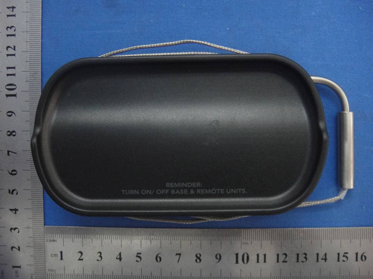
2ACVGBXOBA
Jan 04, 2015KA GMT DIGITAL REMOTE THERMOMETER BLACK
Equipment Class
DSC - Part 15 Security/Remote Control Transmitter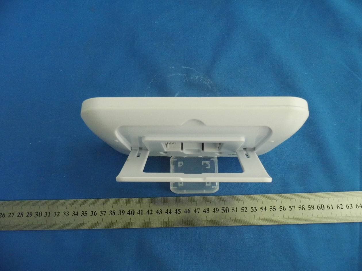
2ACVG-STG-R
Aug 18, 2014WEATHER STATION-RX
Equipment Class
CYY - Communications Receiver used w/Pt 15 Transmitter