2ACWW1300303M2.4G Wireless Serial-module
HULU ROBOTICS TECHNOLOGY COMPANY LIMITED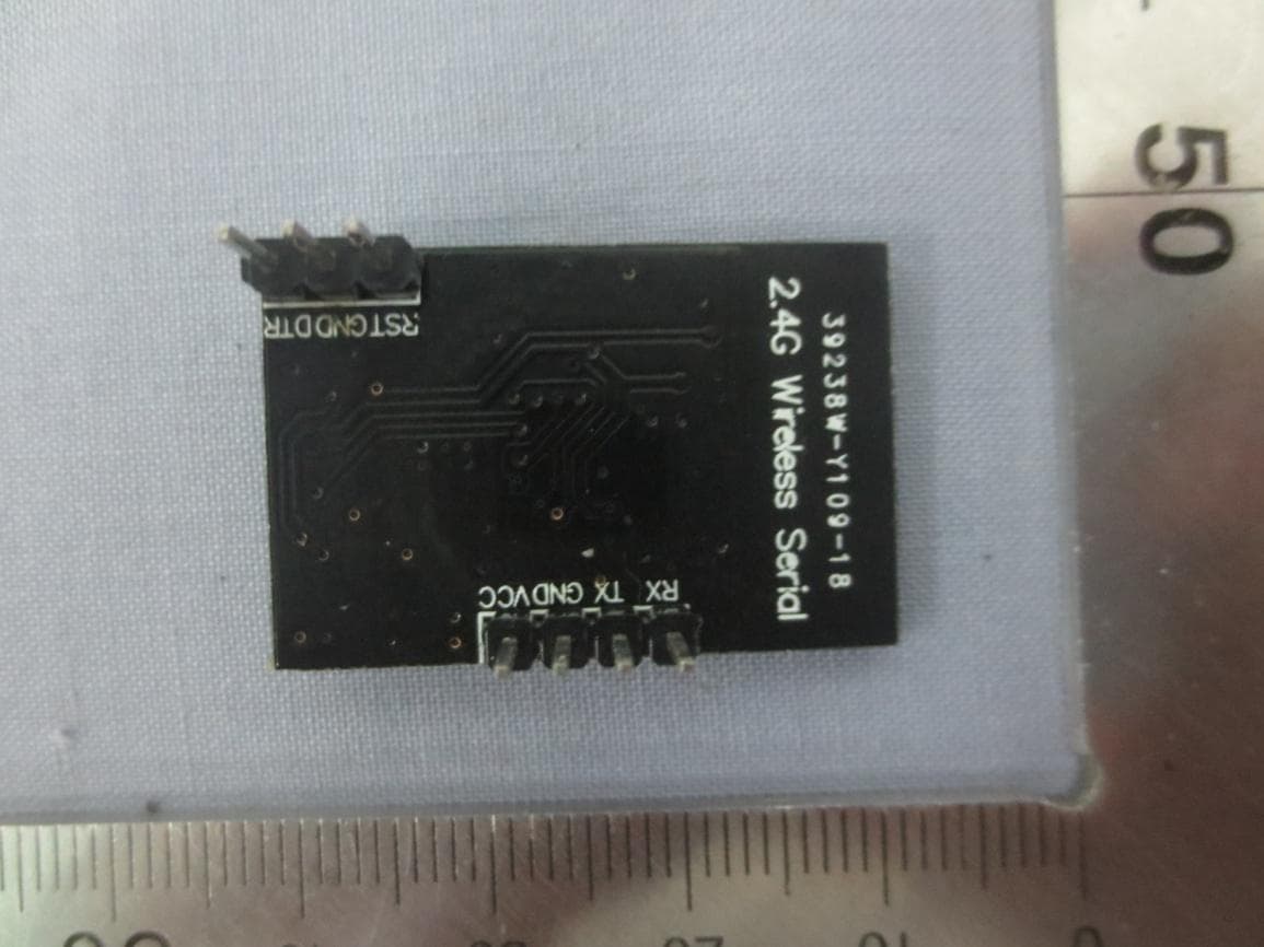
Click to zoom
Application Details
- Equipment Class
- DXX - Part 15 Low Power Communication Device Transmitter
- Date of Grant
- Jun 27, 2015
- Application Purpose
- Original Equipment
- Date of Application
- Jun 25, 2015
- Equipment Note
- 2.4G Wireless Serial-module
- Frequency Range
- 2404.00000000 - 2480.00000000
- Country
- China
Documents & Files
Document Text
Text extracted from the exhibit documents filed with the FCC. Open a document above to read the original.
Users Manual
Operating Instruction of 2.4G Wireless Serial 1. Pin Description Pin Name Type Level Description Remarks VCC 5V power input terminal GND 5V power ground TX OUTPUT 5V Serial communication output RX INPUT 5V Serial communication input DTR OUTPUT 5V Data terminal ready RST INPUT 5V Module reset pin, low level active 2. Function Description: The function of 2.4G Wireless Serial is to convert the 2.4G wireless communication into the serial communication. Namely, it converts the received wireless data into the serial data, or transmits the received serial data in the wireless mode. Duplex communication. The baud rate of the serial communication is fixed to 115200 bps. 3. Direction for Use: (1) 2.4G Wireless Serial matches with 2.4G USB Dongle. The 2.4G Wireless Serial module is installed in the mCore main control board, and the 2.4G USB Dongle is connected to PC, to control the mCore main control board of the 2.4G wireless communication by PC. (2) There are three display situations for the blue status indication light of the 2.4G Wireless Serial module, and these three situations correspond to different operation modes of the module. Slow flash (default status) It indicates to search the latest connection of 2.4G USB Dongle that is connected with it correspondingly. Quick flash Indicate to search the new 2.4G USB Dongle for the connection. Constantly light Indicate the successful connection. <1> Status switching. Press the button in the module to switch between the quick flash status and the slow flash status when the module fails to be connected (in the quick flash or slow flash status). <2> Slow flash. This is the default status when the module is powered on. The module will only search the latest 2.4G USB Dongle that is matched for the connection in this status. At this time, if the corresponding USB Dongle is also in the power-on status, the module will establish the connection with USB Dongle immediately. The status indicator light will be in the constantly light state after it is connected successfully. <3> Quick flash. The module will search any USB Dongle that is not matched with it for the connection in this status. At this time, insert the USB Dongle that is matched with it into the USB port of PC for the power on. The module will establish the connection with USB Dongle immediately, and the status indicator light will be in the constantly light state. <4> Multi-module use. When several pairs of 2.4G modules are used in the same house, it is necessary to enable 2.4G Wireless Serial is in the quick flash status firstly, and then use them after they are matched to connect successfully in pair. In this way, it can communicate between each pair of 2.4G modules without any interference. (3) After 2.4G Wireless Serial is connected with 2.4G USB Dongle successfully, PC implements the 2.4G wireless communication with the mCore main control board, and uses the graphic programming software mBlock to control the mCore main control board. To understand more information on the use of mBlock, click next connection: http://mblock.cc/ This device complies with part 15 of the FCC Rules. Operation is subject to the following two conditions: (1) This device may not cause harmful interference, and (2) this device must accept any interference received, including interference that may cause undesired operation. Changes or modifications not expressly approved by the party responsible for compliance could void the user's authority to operate the equipment. NOTE: This equipment has been tested and found to comply with the limits for a Class B digital device, pursuant to Part 15 of the FCC Rules. These limits are designed to provide reasonable protection against harmful interference in a residential installation. This equipment generates, uses and can radiate radio frequency energy and, if not installed and used in accordance with the instructions, may cause harmful interference to radio communications. However, there is no guarantee that interference will not occur in a particular installation. If this equipment does cause harmful interference to radio or television reception, which can be determined by turning the equipment off and on, the user is encouraged to try to correct the interference by one or more of the following measures: -- Reorient or relocate the receiving antenna. -- Increase the separation between the equipment and receiver. -- Connect the equipment into an outlet on a circuit different from that to which the receiver is connected. -- Consult the dealer or an experienced radio/TV technician for help. This modular complies with FCC RF radiation exposure limits set forth for an uncontrolled environment. This transmitter must not be co-located or operating in conjunction with any other antenna or transmitter. If the FCC identification number is not visible when the module is installed inside another device, then the outside of the device into which the module is installed must also display a label referring to the enclosed module. This exterior label can use wording such as the following: “Contains Transmitter Module FCC ID: 2ACWW1300303M Or Contains FCC ID: 2ACWW1300303M ” when the module is installed inside another device, the user manual of this device must contain below warning statements; 1. This device complies with Part 15 of the FCC Rules. Operation is subject to the following two conditions: (1) This device may not cause harmful interference. (2) This device must accept any interference received, including interference that may cause undesired operation. 2. Changes or modifications not expressly approved by the party responsible for compliance could void the user's authority to operate the equipment. The devices must be installed and used in strict accordance with the manufacturer's instructions as described in the user documentation that comes with the product
Cover Letter(s)
LIMIT Modular approval Declaration letter We ,Hulu Robotics Technology Company Limited apply limited modular approval for Product Name: 2.4G Wireless Serial‐module Model : MBK‐2.4G‐module FCC ID: 2ACWW1300303M According to 996369 D01 Module Equip Auth Guide v01r04 and 15.212 requirement: 1) The radio elements must have the radio frequency circuitry shielded. Physical components and tuning capacitor(s) may be located external to the shield, but must be on the module assembly; Answer : No, Not shielded 2) The module must have buffered modulation/data inputs to ensure that the device will comply with Part 15 requirements with any type of input signal; Answer :Ye s ;All inputs to the modules are buffered through logic or microprocessor inputs. 3)The modular transmitter must have its own power supply regulation. Answer :Ye s ;A low drop out regulator is used for modular power supply regulation. 4) The module must contain a permanently attached antenna, or contain a unique antenna connector, and be marketed and operated only with specific antenna(s), per Sections 15.203, 15.204(b), 15.204(c), 15.212(a), 2.929(b); Answer :Ye s ; Device is equipped with PCB antenna. (5) The module must demonstrate compliance in a stand-alone configuration; Answer : Ye s ,distance between modular and all AEs are longer than 10cm ,refer to setup photo. (6) The module must be labelled with its permanently affixed FCC ID label, or use an electronic display (See KDB Publication 784748 about labelling requirements); Answer :Yes ; The modular has a permanent fixed label, and below statement was listed in the Users Manual;The host device must be labelled to display the FCC ID of the module Contains FCC ID: 2ACWW1300303M (7) The module must comply with all specific rules applicable to the transmitter including all the conditions provided in the integration instructions by the grantee; Answer :Yes ; The module comply with all specific rules applicable to the transmitter including all the conditions provided in the integration instructions by the grantee, Refer to test report and user manual . (8) T Ans Rep The module wer :Yes ports and Ref must compl ; Transm fer to modula ly with RF e itter meets M ar installation exposure req MPE calculati n manual quirements ion of 47 CFRR 1.1307 . RRefer to MPE
External Photos
Report No: CCIS15050031401 Shenzhen Zhongjian Nanfang Testing Co., Ltd. Project No.: CCIS150500314RF No. B-C, 1/F., Building 2, Laodong No.2 Industrial Park, Xixiang Road, Bao’an District, Shenzhen, Guangdong, China Telephone: +86 (0) 755 23118282 Fax: +86 (0) 755 23116366 Page 23 of 23 8 EUT Constructional Details ------End------
ID Label/Location Info
Label : Size˖ ˖20mm*8mm Label Location on EUT: FCC ID:2ACWW1300303M Label Location FCC ID: 2ACWW1300303M
Internal Photos
Report No: CCIS15050031401 Shenzhen Zhongjian Nanfang Testing Co., Ltd. Project No.: CCIS150500314RF No. B-C, 1/F., Building 2, Laodong No.2 Industrial Park, Xixiang Road, Bao’an District, Shenzhen, Guangdong, China Telephone: +86 (0) 755 23118282 Fax: +86 (0) 755 23116366 Page 23 of 23 8 EUT Constructional Details ------End------
RF Exposure Info
RF Exposure evaluation According to 447498 D01 General RF Exposure Guidance v05 The 1-g and 10-g SAR test exclusion thresholds for 100 MHz to 6 GHz at test separation distances≤ 50 mm are determined by: [(max. power of channel, including tune-up tolerance, mW)/(min. test separation distance, mm)] ·[√f(GHz)] ≤ 3.0 for 1-g SAR and ≤ 7.5 for 10-g extremity SAR, where f(GHz) is the RF channel transmit frequency in GHz Power and distance are rounded to the nearest mW and mm before calculation The result is rounded to one decimal place for comparison eirp = pt gt = (E d) 2 /30 where: pt = transmitter output power in watts, gt = numeric gain of the transmitting antenna (unitless), E = electric field strength in V/m, --- 10 (dBuV/m)/20) /10 6 d = measurement distance in meters (m) ---3m Sopt = (E d) 2 /30 gt Field strength =85.91 dBuV/m @3m Ant gain =-3dBi;so Ant numeric gain=0.5 So pt= {[(10 (85.91/20) /10 6 ) 3] 2 /30 0.5} 1000mW =0.23mW So (0.23mW/5mm) √2.44 =0.07 <3 Then SAR evaluation is not required
Test Report
Authorized Bruc Laborat o This report d relate to othe manufacturer this report. This report m than that deta This docum e alteration, fo prosecuted to sample(s) tes 1 Cov Applicant Address Equipmen Product Model N FCC ID: Applicabl Date of sa Date of Te Date of re Test Resu * In the co S d Signature: e Zhang ory Manager details the res er samples of r should ensu may only be re ailed in the re ent cannot be orgery or falsi o the fullest e sted and such ver Pag t: of Applica nt Under Te Name: No.: le standar ample rec est: eport issu ult: onfiguration t Shenzhe r ults of the tes f the same pr ure that all pro eproduced and port, the manu reproduced e fication of the extent of the la h sample(s) ar ge FC Ma ant: Bu Sh est (EUT) 2.4 MB 2A rds: FC ceipt: 11 12 ed: 16 PA tested, the E en Zhon sting carried o roduct and do oducts in serie d distributed in ufacturer mus except in full, e content or aw. Unless oth e retained for CC R aker Works uilding C3, henZhen 5 4G Wireles BK-2.4G-m ACWW130 CC CFR Tit May 2015 2 May to 16 6 Jun., 201 ASS* UT complied ngjian N out on one sam oes not permit es production n full. If the p t ensure the n without prior appearance herwise stated 90 days only. REP s Technolo Floor 4th, 18057 Chi ss Serial-m module 0303M tle 47 Part 5 6 Jun., 201 5 d with the sta Nanfang R mple. The re t the use of th are in confor product in this new system co r written appro of this docum d the results s PO ogy INC Zhiyuan, X na module t 15 Subpa 5 andards spec Testing Report No esults containe he CCIS prod rmity with the report is use d omplies with a oval of the Co ment is unlaw shown in this RT Xili, Nansh art C Sectio cified above. g Co., L : CCIS150 ed in this test duct certificatio product samp d in any config ll relevant sta ompany. Any wful and offen test report ref han District on 15.249 Ltd. 050031401 report do not on mark. The ple detailed in guration other ndards. unauthorize d nders may be fer only to the t, t e n r d e e Shenzhen Zh No. B-C, 1/F Bao’an Distri Telephone: + 2 Ver Versi Prepar Check hongjian Nanfa ., Building 2, L ct, Shenzhen, +86 (0) 755 23 rsion ion No. 00 red By: k By: ang Testing C Laodong No.2 , Guangdong, 3118282 Fax: 16 Pr Co., Ltd. Industrial Par China +86 (0) 755 2 Date Jun., 2015 roject En Review rk, Xixiang Ro 23116366 5 ngineer wer oad, Date: Date: Report N P Descri Orig No: CCIS1 roject No.: CC iption inal 16 Jun., 16 Jun., 150500314 CIS150500314 Page 2 of 2 2015 2015 401 4RF 23 Report No: CCIS15050031401 Shenzhen Zhongjian Nanfang Testing Co., Ltd. Project No.: CCIS150500314RF No. B-C, 1/F., Building 2, Laodong No.2 Industrial Park, Xixiang Road, Bao’an District, Shenzhen, Guangdong, China Telephone: +86 (0) 755 23118282 Fax: +86 (0) 755 23116366 Page 3 of 23 3 Contents Page 1 COVER PAGE ................................................................................................................................................... 1 2 VERSION ........................................................................................................................................................... 2 3 CONTENTS ....................................................................................................................................................... 3 4 TEST SUMMARY .............................................................................................................................................. 4 5 GENERAL INFORMATION .............................................................................................................................. 5 5.1 CLIENT INFORMATION ............................................................................................................................................ 5 5.2 GENERAL DESCRIPTION OF E.U.T. ....................................................................................................................... 5 5.3 TEST MODE ............................................................................................................................................................ 5 5.4 DESCRIPTION OF SUPPORT UNITS ........................................................................................................................ 5 5.5 LABORITORY FACILITY ........................................................................................................................................... 6 5.6 LABORITORY LOCATION......................................................................................................................................... 6 5.7 TEST INSTRUMENTS LIST ....................................................................................................................................... 7 6 TEST RESULTS AND MEASUREMENT DATA ............................................................................................. 8 6.1 ANTENNA REQUIREMENT: ...................................................................................................................................... 8 6.2 CONDUCTED EMISSIONS ....................................................................................................................................... 9 6.3 RADIATED EMISSION ........................................................................................................................................... 12 6.3.1 Field Strength Of The Fundamental Signal .............................................................................................. 14 6.3.2 Spurious Emissions ..................................................................................................................................... 15 6.3.3 Band edge (Radiated Emission) ................................................................................................................ 18 6.4 20DB BANDWIDTH ............................................................................................................................................... 19 7 TEST SETUP PHOTO .........…
Text truncated - open the document above for the full version.
Test Setup Photos
Report No: CCIS15050031401 Shenzhen Zhongjian Nanfang Testing Co., Ltd. Project No.: CCIS150500314RF No. B-C, 1/F., Building 2, Laodong No.2 Industrial Park, Xixiang Road, Bao’an District, Shenzhen, Guangdong, China Telephone: +86 (0) 755 23118282 Fax: +86 (0) 755 23116366 Page 21 of 23 7 Test Setup Photo Radiated spurious emission Report No: CCIS15050031401 Shenzhen Zhongjian Nanfang Testing Co., Ltd. Project No.: CCIS150500314RF No. B-C, 1/F., Building 2, Laodong No.2 Industrial Park, Xixiang Road, Bao’an District, Shenzhen, Guangdong, China Telephone: +86 (0) 755 23118282 Fax: +86 (0) 755 23116366 Page 22 of 23 Conducted Emissions
Contact Information
Applicant
TONY CHEN
Technical Contact
Non-Technical Contact
Shenzhen Zhongjian Nanfang TestingLisa Chen
Test Firm
Shenzhen Zhongjian Nanfang Testing Co.,LtdBruce Zhang
Technical Specifications
| # | Rule Parts | Frequency Range | Power Output |
|---|---|---|---|
| 1 | 15C | 2.40 GHz - 2.48 GHz | - |
Other Applications from HULU ROBOTICS TECHNOLOGY COMPANY LIMITED
2ACWW1300133B
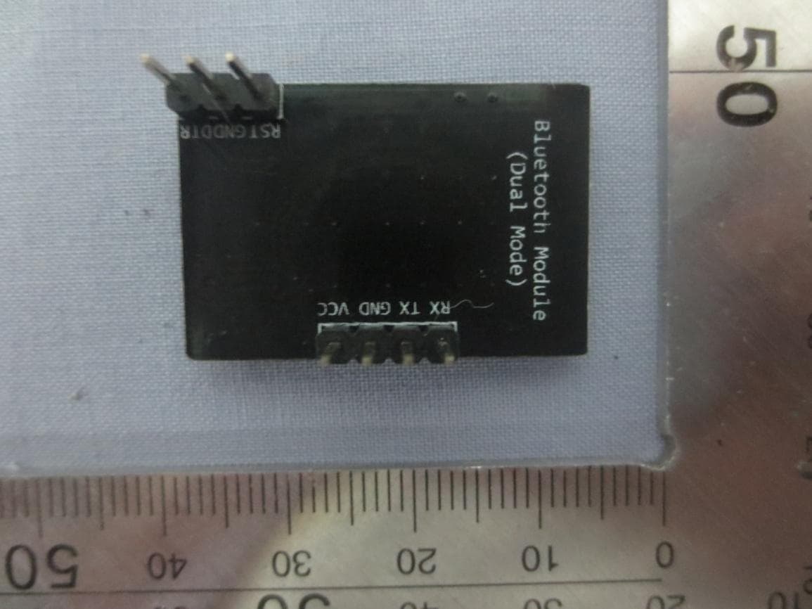
Jun 13, 2015Bluetooth module(Dual mode)
Equipment Class
DTS - Digital Transmission System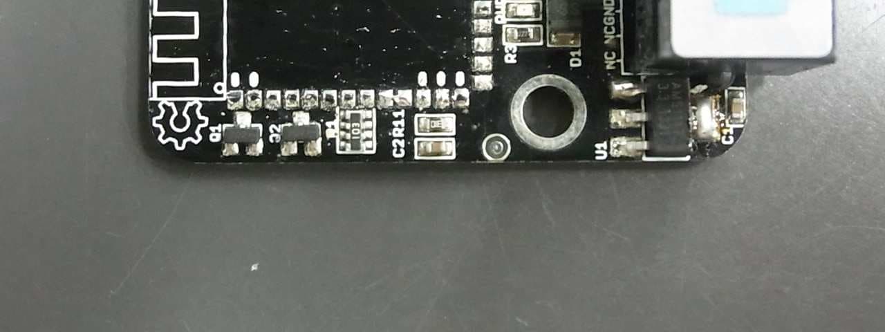
2ACWW13002
Sep 02, 2014Makeblock Bluetooth Module
Equipment Class
DSS - Part 15 Spread Spectrum Transmitter