2AD9XVERSADIntrusion Detector Sensor
Versa Wireless Inc.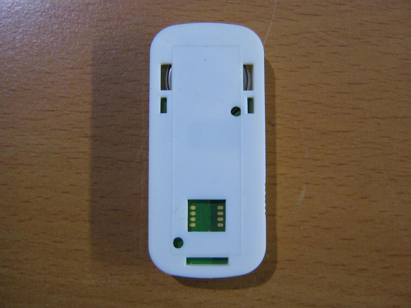
Click to zoom
Application Details
- Equipment Class
- DSC - Part 15 Security/Remote Control Transmitter
- Date of Grant
- Mar 01, 2015
- Application Purpose
- Original Equipment
- Date of Application
- Mar 01, 2015
- Equipment Note
- Intrusion Detector Sensor
- Frequency Range
- 433.92000000 - 433.92000000
- Company
- Versa Wireless Inc.
- Country
- Canada
Documents & Files
Document Text
Text extracted from the exhibit documents filed with the FCC. Open a document above to read the original.
Cover Letter(s)
REQUEST FOR CONFIDENTIALITY Feb 26, 2015 To: Federal Communications Commission Equipment Authorization Branch Laboratory Division Office of Engineering and Technology 7435 Oakland Mills Road Columbia, Maryland 21046 Subject: Request for Confidentiality Applicant: Versa Wireless Inc. 3725 159a Street Surrey BC, Canada V3Z0P1 EQUIPMENT FCC IDENTIFIER: 2AD9XVERSAD Dear Sir or Madam: Some of the material included in this application contains trade secrets and proprietary information not customarily released to the public. Because public disclosure of the material might be harmful to the applicant and provide unjustified benefits to its competitors, it is requested that the following be withheld from public disclosure: Exhibit Type File Name 2AD9XVERSAD-Schematic 2AD9XVERSAD-Block Diagram 2AD9XVERSAD-BOM 2AD9XVERSAD-Internal Photos Trade secrets and proprietary information can be held confidential. Therefore, we wish to invoke the act under the provisions of 47CFR, Sections 0.457(d) and 0.459. Please contact the undersigned if you have any questions or need any further information. Regards, Justin Carlson General Manager Versa Wireless Inc. Phone: 604.807.3235 Email: [email protected]
Cover Letter(s)
February 26.2015 Timco Engineering, Inc. 849 NW State Road 45 P.O. Box 370 Newberry, Florida 32669 RE: Justification for label location regarding application for certification of FCC ID: 2AD9XVERSAD IC Number: 12637-VERSAD To Whom It May Concern: This letter is to justify the choice of label location for the device bearing the above FCC ID and IC Number. The location was chosen to be in the battery compartment due to limited space available to the placement of the label. The device is relatively small in physical size and has many contoured surfaces. The battery cover is not fastened nor permanently affixed to the device enclosure; therefore it was rejected as a potential location. The front side of the device enclosure is the side that the end user sees during normal operation. Versa Wireless Inc. wants to reserve the front side for marketing information (eg. Brand or trademark) and does not want label information on this side. For these reasons, the inside of the battery compartment is the only logical choice. At the factory, the device is assembled without the battery installed and will be marketed in that configuration. For the purpose of replacement by the end user, the battery is designed to be easily removed by hand and without assistance of tools. Once the battery is removed, the label will be visible. For these reasons, the label will be readily viewable to the device’s purchaser and to the end user. Please contact the undersigned if you have any questions or need any further information. Regards, Justin Carlson General Manager Versa Wireless Inc. Phone: 604.807.3235 Email: [email protected]
External Photos
External Photos
Operational Description
VERSA WIRELESS MICRA-D Block Diagram Versa Wireless Operational Description: 1. Overview The device is a security sensor for windows. When the window is opened, a magnet is separated from the reed switch on the sensor, which triggers a change of state on the sensor’s microprocessor. The microprocessor then powers up the RF transmitter (Pulse Width Modulated OOK) and sends a series of 4 identical packets that flag the change of state to a receiver. The 4 packets are sent with a random delay between them of 100 mS to 800 mS. When there is no change of state occurring, the device goes into a very low-power mode, and wakes up 4x a second to check and see if there is a change of state on the reed switch. The sensor times out every 72 minutes and transmits a “heartbeat” message to allow the receiver to know it is still operational. Further, a battery level indicator (ok, or low) is sent with every message packet allowing a service technician to change the battery when it gets low. 2. Battery Section The battery is a Lithium Coin cell (CR2032) size, and is replaceable in the package (clips are J2 & J3). The device operates in three modes, Idle, Monitor, and Transmit. The majority of the time the device is in the “Idle” state, and this is the major contributor to battery life, which is expected to be greater than 7 years typical. C23 provides filtering on the input voltage 3. Microprocessor Section The microprocessor is a TI MSP430G2231 (U1) with onboard Flash and RAM. U1 has a startup delay provided by R1 & C1. The microprocessor samples the Reed Switch (S2) and Tamper Switch (S3) 4x per second and in the event of a change of state will transmit its packets to report this change. When a change of state is detected, or a “heartbeat timeout” occurs, the microprocessor modulates the Tx data line (U1-p7) which powers up and modulates the output of the Max7044 (U2) transmitter. 4. RF Transmitter The RF transmitter is a single frequency OOK transmitter, and R2, R9, C11, C12, C20, C21, & C22 provide filtering to the RF transmitter chip U2 (Max7044). U1 uses a fixed Phase Locked Loop on chip to generate the transmit frequency from a crystal reference (Y1) by x32. C6 & C18 are 0ohm pass through resistors, and C4 is used with the crystal Y1 to set the fixed transmit frequency. L2, C3, L1, C9, C15, C17, C13 & C19 are used to match to the Loop Antenna. R11, R13 & C2 are not populated. Modulation Type is Amplitude Shift Keyed – On/Off keyed (ASK-OOK) The carrier is modulated directly by the data coming from the microprocessor. The protocol uses a form of return-to-zero coding in which the carrier is turned on for the second half of a one-bit, and not turned on at all for a zero bit. Peak frequency deviation is not applicable to ASK The transmission rate is 2 Kbits/sec. The rated output power into the antenna is 13dBm or 20milliWatts. Note: There is provision for the same pcb to be used for a different product (not included in this FCC submission), and that is why there are some additional parts shown on the schematic, and noted by Do Not Populate in boxes.
Test Report
19473 Fraser Way Pitt Meadows, BC Canada V3Y 2V4 ph. 604-527-8378 |fx. 604 527 8388 Electromagnetic Compatibility Test Report FCC CFR47 Part 15 Subpart B, Subpart C 15.231 15.205; RSS Gen issue 4, ICES-003 Issue 5 & RSS 210 issue 8, Annex 1 Report Reference No. .....................: E10676-1402-D Rev 2.0 Date of issue ........................................: February-24-2015 Total number of pages. . . .. .. . ... . .. . ..: 19 Testing Laboratory........................ : Quality Auditing Institute Address................................................ : 16 – 211 Schoolhouse Street, Coquitlam, BC, V3K 4X9, Canada Accreditations (ISO 17025): Standard Council of Canada: Accredited Laboratory No. 743 International Accreditation Service Inc: Accredited Laboratory: No. TL-239 This report has been completed in accordance with the requirements of ISO/IEC 17025. Test results contained in this report are within QAI Laboratories ISO/IEC 17025 accreditation. QAI Laboratories authorizes the applicant to reproduce this report provided it is reproduced in its entirety and for the use by the company’s employees only. Applicant’s name ..............................: Versa Wireless Address......................................: 3725 159A Street, Surrey, BC Canada, V3Z 0P1 Contact.......................................: Justin Carlson, Email ...............: [email protected] Phone.........................................: (604) 807-3235 Test Standard................................ : FCC CFR47 Part 15 Subpart B, Subpart C 15.231 ,15.205; RSS Gen issue 4 & RSS-210 Issue 8 Annex 1 Test item description....................... : Single Protocol Security Sensors: Versa-DSC Manufacturer .....................................: Versa Wireless Model Number.................. .............: Versa-DSC FCC ID ................................. ........: 2AD9XVERSAD IC Certification No. ........................: 12637A-VERSAD Client: Versa Wireless Job No.: E10676-1402-D Date: Feb-24-2015 Page 2 of 19 Security Sensors: Versa-DSC (EUT) Client: Versa Wireless Job No.: E10676-1402-D Date: Feb-24-2015 Page 3 of 19 Revision History Date Report Number Rev # Details Authors Initials Jan-28-2015 E10676-1402-D 0.0 Draft Test Report JQ Jan-28-2015 E10676-1402-D 0.1 Draft Test Report JQ Feb-05-2015 E10676-1402-D 1.0 Final Test Report JQ Feb-24-2015 E10676-1402-D 2.0 Final Test Report JQ All previous versions of this Report have been superseded by the latest dated Revision as listed in the above table. Please dispose of all previous electronic and paper printed revisions accordingly. Client: Versa Wireless Job No.: E10676-1402-D Date: Feb-24-2015 Page 4 of 19 Index EMC TEST SUMMARY....................................................................................................... 5 PRODUCT DESCRIPTION ................................................................................................. 6 EUT DESCRIPTION ........................................................................................................... 6 FACILITIES AND ACCREDITATION .................................................................................. 7 ENVIROMENTAL CONDITIONS: ....................................................................................... 7 TESTING METHODOLOGY ............................................................................................... 7 EUT TESTING CONFIGURATION ..................................................................................... 7 GENERAL TEST PROCEDURES ...................................................................................... 7 MEASUREMENT UNCERTAINTY ..................................................................................... 8 TEST EQUIPMENT LIST .................................................................................................... 8 Part 1 - Radiated Emissions Testing (Unintentional Mode) ................................................ 9 Part 2 - Transmitter Radiated Emissions Testing ............................................................. 10 Part 3 - Duty CycleTesting ................................................................................................ 14 Part 4 - 20 dB Bandwidth Testing ..................................................................................... 16 Part 5 - Transmitter Time Testing ..................................................................................... 17 Test Setup Pictures ........................................................................................................... 18 Client: Versa Wireless Job No.: E10676-1402-D Date: Feb-24-2015 Page 5 of 19 EMC TEST SUMMARY The following tests demonstrate the testimony to “FCC & IC” Mark Electromagnetic compatibility testing for “Versa-DSC” manufactured by Versa Wireless. The testing was performed pursuant to FCC CFR47 Part 15 Subpart B, Subpart C 15.231 15.205; RSS Gen issue 4, ICES-003 Issue 5 & RSS 210 issue 8, Annex 1 Tests were conducted on a sample of the equipment as requested by Versa Wireless for the purpose of demonstrating compliance with FCC CFR47 Part 15 Subpart B, Subpart C 15.231 15.205; RSS Gen issue 4, ICES-003 Issue 5 & RSS 210 issue 8, Annex 1. Versa Wireless is responsible for the tested product configuration, continued product compliance with these standards listed, and for the appropriate auditing of subsequent products, as required. Please note that this list of tests may only comprise a partial list of the tests that are required before a FCC or IC label can be produced by the manufacturer. This is to certify that the following report is true and correct to the best of our knowledge. Test Item Applicable Standard Description Performance Criteria Part 1 Radiated Emissions FCC CFR47 Part 15 Subpart B; RSS Gen issue 4, ICES-003 Issue 5 The emission are measured when the transmitter is not actived. Complies Part 2 Transmitter Radiated Emission FCC CFR47 Part 15 Subpart C 15.231 15.205; RSS Gen issue 4 & RS…
Text truncated - open the document above for the full version.
Test Setup Photos
Test Setup Pictures Radiated emissions test setup below 30MHz Radiated emissions test setup 30-1000MHz Radiated emissions test setup above 1000MHz Worst-Case Orientation
Contact Information
Applicant
Justin Carlson(General Manager)
Test Firm
Quality Auditing Institute Ltd.Lawrence Gibson
[email protected]604-527-8378
Technical Specifications
| # | Rule Parts | Frequency Range | Power Output |
|---|---|---|---|
| 1 | 15.231 | 433.92 MHz - 433.92 MHz | - |
Other Applications from Versa Wireless Inc.

2AD9XLAMP-ZW2
Mar 31, 2024Z-Wave Dimmer Plug(800S)
Equipment Class
DTS - Digital Transmission System
2AD9XSHOCK319
Jan 04, 2023(DSC) Wireless Shock Sensing Security Sensor for Doors/Windows
Equipment Class
DSC - Part 15 Security/Remote Control Transmitter
2AD9XPIRD
Jan 05, 2021Motion Sensor
Equipment Class
DSC - Part 15 Security/Remote Control Transmitter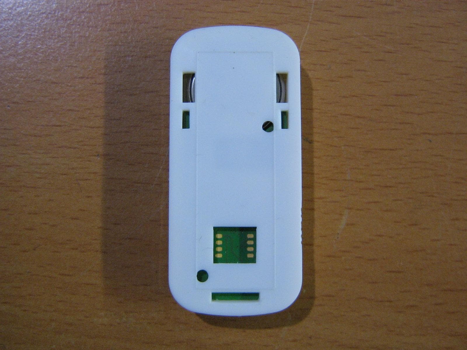
2AD9XVERSAX
Apr 20, 2015Security Sensor
Equipment Class
DSC - Part 15 Security/Remote Control Transmitter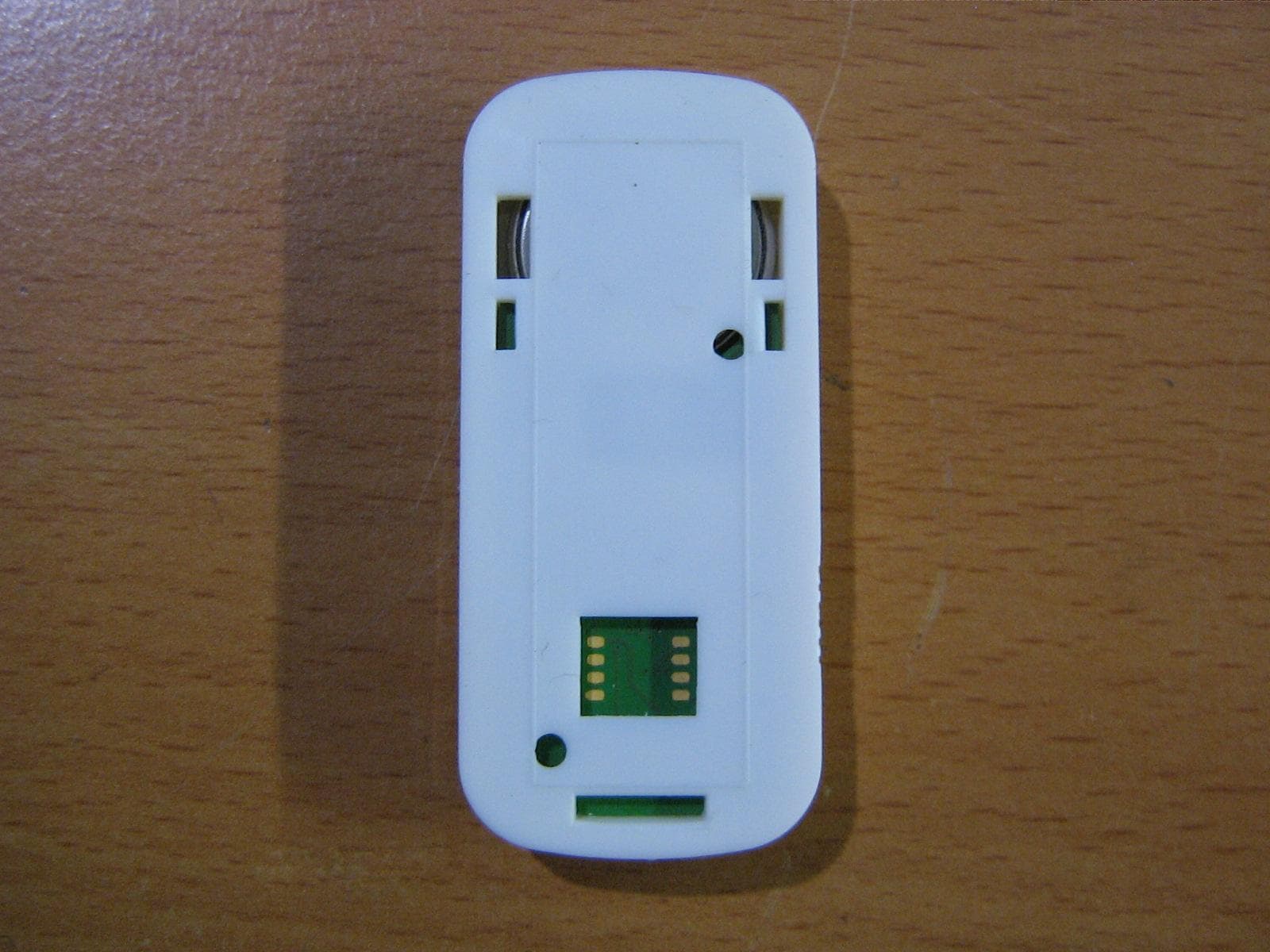
2AD9XVERSAH
Mar 01, 2015Intrusion Detector Sensor
Equipment Class
DSC - Part 15 Security/Remote Control Transmitter