2ADEK102014SBP1SOBI Controller
Social Bicycles LLCApplication Details
- Equipment Class
- DXX - Part 15 Low Power Communication Device Transmitter
- Date of Grant
- Nov 24, 2014
- Application Purpose
- Original Equipment
- Date of Application
- Nov 24, 2014
- Equipment Note
- SOBI Controller
- Frequency Range
- 13.56000000 - 13.56000000
- Company
- Social Bicycles LLC
- Country
- United States
Documents & Files
Document Text
Text extracted from the exhibit documents filed with the FCC. Open a document above to read the original.
Users Manual
SOBI CONTROLLER OPERATOR GUIDE Table of Contents Getting Started Getting to Know your Device 3 Frequently Asked Questions 5 Overview 7 Step 1: Insert Controller into a Social Bicycle 7 Step 2: Secure the Controller 7 Step 3: Connect and insert battery 7 Step 4: Soft Reboot your Controller 7 Step 5: Add Controller to your SoBi network 7 Step 6: Verify your Controller is Working 7 Things to Know N Trouble Shooting Help with Activating your Controller 8 Help after Activating your Controller 8 Additional Information Understanding the lights on your Controller 9 Specifications 10 FCC Compliance 11 RF Exposure 12 This page intentionally left blank. 45 LCD Indicator LEDs Keypad Male Battery Connector Battery Rear Lens Security Screws Female Battery Connector DC Barrel Plug Female Lock Connector Programming Connector Getting to Know your Device SoBi Controller Operator Guide | Getting Started DEVICE INTERFACE LCD Screen: The LCD screen dis- plays information to the Operator and to the End-consumer. It informs them of how to interact with the Controller. Indicator LEDs: The four (4) indicator LEDs show the current status of the bike. These let the operator quickly know whether a bike is working, rented or in repair. Keypad: The Controller’s keypad includes ten (10) numeric keys, three (3) soft keys that correspond to content displayed on the LCD screen and two (2) large buttons for confirmation and cancelation of com- mands entered at the keypad. DEVICE CONNECTORS Female Lock Connector: A SoBi Controller requires a SoBi Lock and Social Bicycle to be useful for a bike share operator. Plug the Lock’s cable into this connector. See the SoBi Lock Operator Guide for details. SoBi Controller Operator Guide | Getting Started Programming Connector: The SoBi Controller can be reprogrammed over the air (OTA) or by connecting the device to a Windows PC running Atmel Studio 6. Reprogramming is only to be done at direction of SoBi service center staff. DC Barrel Plug: The DC barrel plug allows for rapid device charging. REMOVABLE PARTS Battery: Each SoBi Controller ships with one 4.2V Lithium Ion Battery Pack (part No. SC2-BAT-15A64V2). This battery is connected Rear Lens: Each SoBi Controller ships with a rear lens cover secured by 2 security screws. The lens cover provide operators with secure ac- cess to the Controller’s battery com- partment. When needed, remove this cover to swap batteries. Security Screws: Each SoBi Con- troller comes with two (2) custom security screws and two (2) T-10 security screws. Use these to secure the Controller to the SoBi bike. Getting to Know your Device (continued) 67 This guide will take you step-by-step through configuration and confirmation. SoBi Controller Operator Guide | Additional Information STEP 1 Insert your Controller into a Social Bicycle and connect it to your SoBi Lock. STEP 2 Secure your Controller to the Social Bicycle using the 2 security screws and a torque wrench. STEP 3 Connect the battery to power on your Controller and attach the rear lens cover to secure the battery. STEP 4 Soft reboot your Controller by entering the code provided to you by the SoBi service center staff. STEP 5 If asked: enter your SoBi Network ID and Bike ID. STEP 6 Verify that your Controller is working by using it to rent and unlock the Social Bicycle which you installed it on during Step 1. Overview SoBi Controller Operator Guide | Getting Started Why did my Controller’s indicator LEDs cycle through different colors when I turned it on? When a controller is first turned on it will establish a connection with the SoBi Platform. It will transition through a range of red, yellow, blue and green LEDs as it establishes its network connection and verifies whether it is assigned to a Bike Share network. The Controller asked me to enter my bike share program’s Network ID. Where do I find this ID? Operator staff with access to the SoBi Platform can login to see the ID of their network. The Network ID is listed at the top of the Web App. How do I know what Bike ID to assign the Controller? When first starting up a Controller it may ask you for a Network ID and a Bike ID. The Bike ID is a 3 to 4 digit number printed on the Social Bicycle onto which you are installing the Controller. How do I know if the Controller is successfully reporting GPS? You have two options for determin- ing if the Controller is connecting with GPS satellites. The first is to see if rides it records include a route. The second is to enter the appropriate Admin code to see a readout on the Controller’s LCD. Contact your SoBi service center for this keycode. My Controller does not appear to be connecting to the GSM network. What should I do? The Controller should be installed in a Social Bicycle with clear sky access or in a building by a wall iwth windows. If the Controller is located in an area (such as some building basements) without GSM signal it will not be able to connect to the SoBi Platform. How do I unlock a Social Bicycle using the Controller? Enter your 6-digit SoBi account num- ber or tap your SoBi RFID card. Then enter your 4-digit PIN. Frequently Asked Questions 89 Understanding the lights on your Controller SoBi Controller Operator Guide | Additional Information Red Indicator LEDs: The Controller is in a repair state. This prevents your bike share members from renting the bike. The bike will not show as available in the SoBi web or mobile applications and you will receive a Maintenance Record alert. To remove a Controller from the Repair state, use the SoBi web app for Operators at manage. socialbicycles.com or enter the Repair Code X9+005 at the bike. Blue Indicator LEDs: The Controller is rented by a member of your Social Bicycles Network. To know which user has your bike rented use the SoBi web app for Operators. If you need to end the rental, use the web app to cancel the hold if the bike is locked or if the bike is unlocked, insert the lockbar to end the rental. Yellow Indicator LEDs: The Controlle…
Text truncated - open the document above for the full version.
Test Report
Page 1 of 22 The test results relate only to the individual items which have been tested. This report shall not be reproduced in parts without the written approval of the testing laboratory © Copyright: All rights reserved by CETECOM Laboratory Accreditation and Listings Reg. No.: 736496 MRA US-EU 0003 Industry Canada Reg. No.: 3462D-1 Reg. No.: 3462D-2 Reg. No.: 3462D-3 Voluntary Controls for Electromagnetic Emissions Reg. No.: R-2666 C-2914, T-1967, G-301 accredited according to DIN EN ISO/IEC 17025 CETECOM GmbH Laboratory Radio Communications & Electromagnetic Compatibility Im Teelbruch 116 • 45219 Essen • Germany Registered in Essen, Germany, Reg. No.: HRB Essen 8984 Tel.: + 49 (0) 20 54 / 95 19-954 • Fax: + 49 (0) 20 54 / 95 19-964 E-mail: [email protected] • Internet: www.cetecom.com Annex 4: Diagrams to T E S T R E P O R T No.: 2-0128-14-1-4a-C1 Model SB1 (RFID mode) FCC ID: 2ADEK102014SBP1 IC Certification Number: 12433A-102014SBP1 According to: FCC Regulations Part 15.207, Part 15.225, Part 15.209 IC-Regulations RSS-Gen, Issue 4 RSS-210, Issue 8 ICES-003, Issue 5 Social Bicycles Inc. for Test Report TR2-0128-14-1-4a-Annex4 C1, Page 2 of 22 TR2-0128-14-1-4a-A4-C1 Table of contents 1. DIAGRAMS ......................................................................................................................................................... 3 1.1. Radiated field strength emission mask at 13.110-14.010MHz ........................................................................ 3 1.2. General Limit - Radiated field strength emissions below 30 MHz .................................................................. 5 1.3. General Limit - Radiated field strength emissions, 30 MHz - 1 GHz .............................................................. 6 1.4. Frequency error(tolerance) .............................................................................................................................. 7 1.5. Occupied bandwidth ........................................................................................................................................ 22 Test Report TR2-0128-14-1-4a-Annex4 C1, Page 3 of 22 TR2-0128-14-1-4a-A4-C1 1. Diagrams 1.1. Radiated field strength emission mask at 13.110-14.010MHz Diagram No. 2.01 Date: 28.10.2014 Page 1 of 3 Test description: Magnetic Field strength Measurement related to 30 m distance Test site and distance: Ref.-Nr. 441 Semi Anechoic Room (SAR) with 3 m measurement distance Version of Test software: EMC32 V8.51.0 Distance correction: used accord. table, pls. see test report Technical Data: Please see page 2 for detailed data of measurement setup Rec. antenna (pre-scan): height 1.00 m, parallel and 90° to EUT polarisation Used filter: bypass Test specification: FCC 15.225; RSS-210, Issue 8 Operator: KRe Operating conditions: RFID, TX-on Power during tests: Battery 4V Comment 1: EUT placed horizontal/laying Final Result 1 Frequenc y (MHz) QuasiPea k (dBμV/m) Meas. Time (ms) Bandwidt h (kHz) Polarizatio n Corr . (dB) Margi n (dB) Limit (dBμV/m ) 13.561000 35.8 1000.0 10.000 H 0.4 48.20 84.00 0 5 10 15 20 25 30 35 40 45 50 55 60 65 70 75 80 85 90 12 12,5 13 13,5 14 14,5 15 Le vel i n dB μV /m F re q u e n c y in M H z 0 1 _ F C C 1 5 .2 0 9 _ ma g n h o r+ v e rt_ In _ B a n d _ 1 3 .5 6 M H z_ n o _ k ip p F C C 1 5 .2 2 5 Test Report TR2-0128-14-1-4a-Annex4 C1, Page 4 of 22 TR2-0128-14-1-4a-A4-C1 Diagram No. 2.02 Date: 28.10.2014 Page 1 of 3 Test description: Magnetic Field strength Measurement related to 30 m distance Test site and distance: Ref.-Nr. 441 Semi Anechoic Room (SAR) with 3 m measurement distance Version of Test software: EMC32 V8.51.0 Distance correction: used accord. table, pls. see test report Technical Data: Please see page 2 for detailed data of measurement setup Rec. antenna (pre-scan): height 1.00 m, parallel and 90° to EUT polarisation Used filter: bypass Test specification: FCC 15.225; RSS-210, Issue 8 Operator: KRe Operating conditions: RFID, TX-on Power during tests: Battery 4V Comment 1: EUT placed vertical Final Result 1 Frequenc y (MHz) QuasiPea k (dBμV/m) Meas. Time (ms) Bandwidt h (kHz) Polarizatio n Corr . (dB) Margi n (dB) Limit (dBμV/m ) 13.561000 44.6 1000.0 10.000 H 0.4 39.40 84.00 0 5 10 15 20 25 30 35 40 45 50 55 60 65 70 75 80 85 90 12 12,5 13 13,5 14 14,5 15 Le vel i n dB μV /m F re q u e n c y in M H z 0 1 _ F C C 1 5 .2 0 9 _ ma g n h o r+ v e rt_ In _ B a n d _ 1 3 .5 6 M H z_ n o _ k ip p F C C 1 5 .2 2 5 Test Report TR2-0128-14-1-4a-Annex4 C1, Page 5 of 22 TR2-0128-14-1-4a-A4-C1 1.2. General Limit - Radiated field strength emissions below 30 MHz Diagram No. 2.03_RX_RSE Date: 28.10.2014 Page 1 of 2 Test description: Magnetic Field strength Measurement related to 30/300 m distance Test site and distance: Ref.-Nr. 441 Semi Anechoic Room (SAR) with 3 m measurement distance Version of Test software: EMC32 V8.51.0 Distance correction: used accord. table, pls. see test report Technical Data: Please see page 2 for detailed data of measurement setup Rec. antenna (pre-scan): height 1.00 m, parallel and 90° to EUT polarisation Used filter: bypass Test specification: FCC 15.205 § 15.209; RSS-Gen: Issue 3 Operator: Lor Operating conditions: RFID, TX-on Power during tests: 4.1V DC Comment 1: Channel nominal - 100 - 80 - 60 - 40 - 20 0 20 40 50 9k203050100 k20 030 050 01M2M3M5M10M2030 M Le vel i n dB μV /m F re q u e n c y in H z F C C 1 5 .2 0 9 _ ma g n h o r+ v e rt F C C 1 5 .2 0 9 _ M a g n e tic _ F ie ld F C C 1 5 .2 0 9 _ A V _ 2 1 3 ,5 6 0 0 0 0 M H z 44,757 dBμV/m Test Report TR2-0128-14-1-4a-Annex4 C1, Page 6 of 22 TR2-0128-14-1-4a-A4-C1 1.3. General Limit - Radiated field strength emissions, 30 MHz - 1 GHz Diagram No. 3.01_TX_RSE 29.10.2014 Page 1 of 2 Test description: Electric Field strength Measurement Test site and distance: Ref.-Nr. 441 Semi Anechoic Room (SAR) with 3 m measurement distance Version of Test software: EMC32 V8.51.0 Distance correction: not used Used filter: not used Tec…
Text truncated - open the document above for the full version.
Test Setup Photos
Page 1 of 4 The test results relate only to the individual items which have been tested. This report shall not be reproduced in parts without the written approval of the testing laboratory © Copyright: All rights reserved by CETECOM Laboratory Accreditation and Listings Reg. No.: 736496 MRA US-EU 0003 Industry Canada Reg. No.: 3462D-1 Reg. No.: 3462D-2 Reg. No.: 3462D-3 Voluntary Controls for Electromagnetic Emissions Reg. No.: R-2666 C-2914, T-1967, G-301 accredited according to DIN EN ISO/IEC 17025 CETECOM GmbH Laboratory Radio Communications & Electromagnetic Compatibility Im Teelbruch 116 • 45219 Essen • Germany Registered in Essen, Germany, Reg. No.: HRB Essen 8984 Tel.: + 49 (0) 20 54 / 95 19-954 • Fax: + 49 (0) 20 54 / 95 19-964 E-mail: [email protected] • Internet: www.cetecom.com Annex 3: Test set-up photographs to T E S T R E P O R T No.: 2-0128-14-1-4a-C1 Model SB1 (RFID mode) FCC ID: 2ADEK102014SBP1 IC Certification Number: 12433A-102014SBP1 According to: FCC Regulations Part 15.207, Part 15.225, Part 15.209 IC-Regulations RSS-Gen, Issue 4 RSS-210, Issue 8 ICES-003, Issue 5 Social Bicycles Inc. for Annex 3 to Test Report 2-0128-14-1-4a-C1, Page 2 of 4 TR2-0128-14-1-4a-A3-C1 Table of contents 1. TEST SET-UP PHOTOGRAPHS ..................................................................................................................... 3 Annex 3 to Test Report 2-0128-14-1-4a-C1, Page 3 of 4 TR2-0128-14-1-4a-A3-C1 1. Test set-up photographs Test setup in semi anechoic chamber, worst case position, close up view Test setup in semi anechoic chamber, worst case position, long shot view Annex 3 to Test Report 2-0128-14-1-4a-C1, Page 4 of 4 TR2-0128-14-1-4a-A3-C1 Test setup in radio lab, EUT inside climatic chamber Test setup in radio lab, EUT inside climatic chamber
Contact Information
Applicant
Noah Sylvan
Test Firm
cetecom advanced GmbHGerald Schmidt
Technical Specifications
| # | Rule Parts | Frequency Range | Power Output |
|---|---|---|---|
| 1 | 15C | 13.56 MHz - 13.56 MHz | - |
Other Applications from Social Bicycles LLC
2ADEKJUMPPACK25
Apr 12, 2020Rechargeable Li-ion battery pack
Equipment Class
DXX - Part 15 Low Power Communication Device Transmitter
2ADEKSLEEVES10
Mar 23, 2020S10 R(H)
Equipment Class
DXX - Part 15 Low Power Communication Device Transmitter
2ADEK-191230
Mar 21, 2020Holster
Equipment Class
DXX - Part 15 Low Power Communication Device Transmitter
2ADEK-191220
Mar 21, 2020Holster
Equipment Class
DXX - Part 15 Low Power Communication Device Transmitter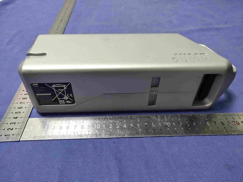
2ADEKJUMPPACK
Jan 06, 2020Rechargeable Li-ion Battery Pack
Equipment Class
DXX - Part 15 Low Power Communication Device Transmitter