2ADIW-N-0003Massage Chair
Henglin Home Furnishings Co., Ltd.
Click to zoom
Application Details
- Equipment Class
- DSS - Part 15 Spread Spectrum Transmitter
- Date of Grant
- Mar 17, 2020
- Application Purpose
- Original Equipment
- Date of Application
- Mar 17, 2020
- Equipment Note
- Massage Chair
- Frequency Range
- 2402.00000000 - 2480.00000000
- Country
- China
Documents & Files
Document Text
Text extracted from the exhibit documents filed with the FCC. Open a document above to read the original.
Users Manual
NOUHAUS massage chairs are warranted for a period of : 1 year Against 1 . Missing materials from the Product at the time of delivery; 2. Defects in the manufacturing of materials used for the Products at the time of delivery; 3. Failure of the Products to correspond with the description in the applicable contract of sale at the time of delivery; and 4. Major defects in the functional department, such as : Skeletal steel frame failure Airbag failure Power failure Remote control failure Massage ball failure Recline tension mechanism failure Subject to the following: Any replacement parts shall be sent to the address of the original purchaser, replaced parts may be recollected by NOUHAUS to be disposed; to benefit under this warranty, NOUHAUS must be notified of any defect within 14 days of the occurrence of such defect via an image or video of the relevant defect sent electronically to [email protected] , and after inspection and acceptance by NOUHAUS; to the extent permitted under the applicable Federal and State law of the United States of America, all parts replaced or repaired under this warranty shall be warranted for the remainder of the designated Warranty Period. What Our Warranty Does Not Cover All warranties listed on this page exclude the following where permitted under the applicable Federal and State law of the United States of America: 1 . Excludes normal wear and tear of surfaces that are not attributable to manufact- uring, including but not limited to (a) degradation of upholstery (PU leather / fabric / genuine leather / mesh), top portion of armrests, pillows, casters exterior or mesh stitching, (b) damage to plastic coverings, (c) variance of tightness of mechanisms, and (d) excludes damage from accidents, natural disasters, physical damage from pets, fire and flood, and non-manufacturing incidents covered under insurance policies (regardless of whether you are in possession of the relevant insurance), (e) excludes any variations in dimensions and color; 2. Any claims for indirect, consequential or incidental losses. 3. Damage to a product that has been modified or altered without the written permission of NOUHAUS; 4. Damage caused to all NOUHAUS products during self-assembly due to failure to adhere to the relevant self-assembly manual instructions provided; 5. Minor misalignments, variations arising out of hand-made workmanship. To e nsure your product enjoyment and safety, and protection under the “Warranty Period”, please ensure you have NOUHAUS assembly and care guidelines for this product, and follow them for the correct assembly and care for your item. Contact our Customer Service Team to obtain these guidelines if you do not have them. NOUHAUS, Inc. 2530 Corporate Pl. #A-112 Monterey Park, CA 91754
External Photos
ReportNo.:EED32L00286801Page99of112 PHOTOGRAPHSOFEUTConstructionalDetails TestmodelNo.:2ADIW-N-0003 ViewofProduct-1 ViewofProduct-2 ReportNo.:EED32L00286801Page100of112 ViewofProduct-3 ViewofProduct-4 ReportNo.:EED32L00286801Page101of112 ViewofProduct-5 ViewofProduct-6
ID Label/Location Info
FCC ID:2ADIW-N-0003 Massage Chair N-0003 AC110-120V 50/60Hz 0.66A Nouhaus, lnc. 2530 Corporate PI, Suite A112 Monterey Park, CA 91754 LabelLocation
Internal Photos
ReportNo.:EED32L00286801Page102of112 ViewofProduct-7 ViewofProduct-8 ReportNo.:EED32L00286801Page103of112 ViewofProduct-9 ViewofProduct-10 ReportNo.:EED32L00286801Page104of112 ViewofProduct-11 ViewofProduct-12 ReportNo.:EED32L00286801Page105of112 ViewofProduct-13 ViewofProduct-14 ReportNo.:EED32L00286801Page106of112 ViewofProduct-15 ViewofProduct-16 ReportNo.:EED32L00286801Page107of112 ViewofProduct-17 ViewofProduct-18 ReportNo.:EED32L00286801Page108of112 ViewofProduct-19 ViewofProduct-20 ReportNo.:EED32L00286801Page109of112 ViewofProduct-21 ViewofProduct-22 ReportNo.:EED32L00286801Page110of112 ViewofProduct-23 ViewofProduct-24 ReportNo.:EED32L00286801Page111of112 ViewofProduct-25 ViewofProduct-26 ReportNo.:EED32L00286801Page112of112 ViewofProduct-27 ***EndofReport*** Thetestreportiseffectiveonlywithbothsignatureandspecializedstamp,Theresult(s)showninthis reportreferonlytothesample(s)tested.WithoutwrittenapprovalofCTI,thisreportcan’tbereproduced exceptinfull.
RF Exposure Info
Re port No. : EED32L00286802Page 1 of 9 1 COVER PAGE RF Expo sure Evaluation Report Product:massage chair Trade mark: Model/Type reference : 2ADIW-N-0003 Serial Number: N/A Report Number: EED32L00286802 FCC ID: 2ADIW-N-0003 Date of Issue: Dec. 27, 2019 Test Standards: 47 CFR Part 1.1307(2015) 47 CFR Part 1.1310(2015) KDB447498D01v06 Test result: PASS Prepa red for: H englin Home Furnishings Co.,Ltd No.378、380 ,Jiaxi Road,Dipu Street, Anji County,Huzhou,Zhejiang Prepa red by : C entre Testing International Group Co., Ltd. Hongwei Industrial Zone, Bao’an 70 District, Shenzhen, Guangdong, China TEL: +86-755-3368 3668 FAX: +86-755-3368 3385 T ested By:Compiled by: Mark ChenSunlight Sun Reviewed by:Approved by: Ware Xin Kevin Yang Date:Dec. 27, 2019 C heck No.:3915686378 Re port No. : EED32L00286802Page 2 of 9 2 Ver sion Ve rsion No.DateDescription 00Dec. 27, 2019O riginal Re port No. : EED32L00286802Page 3 of 9 3 Content s Page 1 CO VER PAGE....................................................................................................................................................................1 2 VERSION.............................................................................................................................................................................2 3 CONTENTS.........................................................................................................................................................................3 4 GENERAL INFORMATION..............................................................................................................................................4 4.1 C LIENT I NFORMATION .. .................................................................................................................................................4 4.2 G ENERA L D ESC RIPTION OF EUT................................................................................................................................4 4.3 P RODUCT S PECIFICATION SUBJECTIVE TO THIS STANDARD .......................................................................................5 4.4 T EST L OCATION .. ..........................................................................................................................................................6 4.5 D EVI ATION FROM S TAND ARDS .. ...................................................................................................................................6 4.6 A BNOR MALITIES FROM S TAND ARD C ON DITIONS .. .......................................................................................................6 4.7 O THER I NFORMATION R EQUESTED BY THE C USTOMER .............................................................................................6 5 RF EXPOSURE EVALUATION.......................................................................................................................................7 5.1 RF E X POSURE C OM PLIANCE R EQUI REMENT ..............................................................................................................7 5.2 M AX IMUM P ERM ISSIBLE E X POSURE .. ..........................................................................................................................8 PHOTOGRAPHS OF EUT CONSTRUCTIONAL DETAILS..........................................................................................9 Re port No. : EED32L00286802Page 4 of 9 4 Gene ral Information 4.1 C lient Information App licant: Henglin Home Furnishings Co., Ltd Address of Applicant: No.378、380 , Jiaxi Road, Dipu Street,Anji County, Huzhou, Zhejiang Manufacturer: Henglin Home Furnishings Co., Ltd Address of Manufacturer: No.378、380 , Jiaxi Road, Dipu Street,Anji County, Huzhou, Zhejiang Factory: Henglin Home Furnishings Co., Ltd Address of Factory: No.378、380 , Jiaxi Road, Dipu Street,Anji County, Huzhou, Zhejiang 4.2 Gen eral Description of EUT Product Name: massage chair ModelNo.(EUT ): 2ADIW -N-0003 Tr ade Mark: EUT Supports Radi os application BT 2.1+EDR Single mode, 2402MHz to 2480MHz Re port No. : EED32L00286802Page 5 of 9 B luetooth : Antenna Gain : 1.08 dBi1.28)(Numeric gain: 4.3 Product Specification subjective to this standard Fr equency Range: 2402MHz to 2480MHz Modulation Type: GFSK, π/4DQPSK,8DPSK Number of Channels: 79 Test Power Grade:TX power:7 Test Software of EUT:AppoTech RF Control Kit.exe Antenna Type: PCB Antenna Antenna Specification Maximum tune up power B luetooth: -7 .00 dB m (0 .200 mW ) Powe r Supply: AC120V/60Hz Sample Received Date: Oct.. 10, 2019 Sample tested Date: Oct.. 10, 2019 to Dec. 16, 2019 The tested sample(s) and the sample information are provided by the client. Re port No. : EED32L00286802Page 6 of 9 4.4 Test Location All tests w ere performed at: Centre Testing International Group Co., Ltd Building C, Hongwei Industrial Park Block 70, Bao'an District, Shenzhen, China Telephone: +86 (0) 755 33683668 Fax:+86 (0) 755 33683385 No tests were sub-contracted. FCC Designation No.: CN1164 4.5 Deviation from Standards None . 4.6 Abnormalities from Standard Conditions None . 4.7 Other Information Requested by the Customer None . Re port No. : EED32L00286802Page 7 of 9 5 RF Expos ure Evaluation 5.1 RF Exposure Compliance Requirement Given d GP E 30 & 377 2 E S W hereE = Field strength in Volts / meter P = Power in Watts G = Numeric antenna gain d = Distance in meters S = Power density in milliwatts / square centimeter Combining equations and re-arranging the terms to express the distance as a function of the remaining variables yields: 2 377 30 d GP S Chan ging to units of mW and cm, using: P (mW) = P (W) / 1000 and d (cm) = d(m) / 100 Yields 22 0796.0 100/377 1000/30 d GP d GP S Equat ion 1 Whered = Distance in cm P = Power in mW G = Numeric antenna gain S = Power density in mW / cm 2 Re port No. : EED32L00286802Page 8 of 9 5.2 Maxi mum Permissible Exposure Subs tituting the MPE safe distance using d = 20 cm into Equation…
Text truncated - open the document above for the full version.
Test Report
ReportNo.:EED32L00286801Page 1 of 112 1COVERPAGE TESTREPORT Product:massagechair Trademark: Model/Typereference: 2ADIW-N-0003 SerialNumber: N/A ReportNumber: EED32L00286801 FCCID: 2ADIW-N-0003 DateofIssue:: Dec.27,2019 TestStandards : 47CFRPart15SubpartC Testresult : PASS Preparedfor: HenglinHomeFurnishingsCo.,Ltd No.378、380,JiaxiRoad,DipuStreet, AnjiCounty,Huzhou,Zhejiang Preparedby : CentreTestingInternationalGroupCo.,Ltd. HongweiIndustrialZone,Bao’an70District, Shenzhen,Guangdong,China TEL:+86-755-33683668 FAX:+86-755-33683385 Compiledby:Reviewedby: SunlightSunWareXin Approvedby:Date:Dec.27,2019 KevinYang CheckNo.:3915686378 ReportNo.:EED32L00286801Page2of112 2Version VersionNo.Date Description 00Dec.27,2019Original ReportNo.:EED32L00286801Page3of112 3TestSummary TestItemTestRequirementTestmethodResult AntennaRequirement 47CFRPart15,SubpartCSection 15.203/15.247(c) ANSIC63.10-2013PASS ACPowerLineConducted Emission 47CFRPart15,SubpartCSection 15.207 ANSIC63.10-2013PASS ConductedPeakOutput Power 47CFRPart15,SubpartCSection 15.247(b)(1) ANSIC63.10-2013PASS 20dBOccupiedBandwidth 47CFRPart15,SubpartCSection 15.247(a)(1) ANSIC63.10-2013PASS CarrierFrequencies Separation 47CFRPart15,SubpartCSection 15.247(a)(1) ANSIC63.10-2013PASS HoppingChannelNumber 47CFRPart15,SubpartCSection 15.247(b) ANSIC63.10-2013PASS DwellTime 47CFRPart15,SubpartCSection 15.247(a)(1) ANSIC63.10-2013PASS PseudorandomFrequency HoppingSequence 47CFRPart15,SubpartCSection 15.247(b)(4)&TCBExclusionList (7July2002) ANSIC63.10-2013PASS Band-edgeforRF ConductedEmissions 47CFRPart15SubpartCSection 15.247(d) ANSIC63.10-2013PASS RFConductedSpurious Emissions 47CFRPart15,SubpartCSection 15.247(d) ANSIC63.10-2013PASS RadiatedSpurious emissions 47CFRPart15,SubpartCSection 15.205/15.209 ANSIC63.10-2013PASS Restrictedbandsaround fundamentalfrequency (RadiatedEmission) 47CFRPart15SubpartCSection 15.205/15.209 ANSIC63.10-2013PASS Remark: TestaccordingtoANSIC63.4-2014&ANSIC63.10-2013. Thetestedsamplesandthesampleinformationareprovidedbytheclient. ReportNo.:EED32L00286801Page4of112 4Content 1COVERPAGE.....................................................................................................................................................................1 2VERSION..............................................................................................................................................................................2 3TESTSUMMARY................................................................................................................................................................3 4CONTENT.............................................................................................................................................................................4 5TESTREQUIREMENT.......................................................................................................................................................5 5.1T ESTSETUP ...................................................................................................................................................................5 5.1.1ForConductedtestsetup...................................................................................................................................5 5.1.2ForRadiatedEmissionstestsetup...................................................................................................................5 5.1.3ForConductedEmissionstestsetup...............................................................................................................6 5.2T EST E NVIRONMENT ......................................................................................................................................................6 5.3T EST C ONDITION ............................................................................................................................................................6 6GENERALINFORMATION...............................................................................................................................................7 6.1C LIENT I NFORMATION ....................................................................................................................................................7 6.2G ENERAL D ESCRIPTIONOF EUT..................................................................................................................................7 6.3P RODUCT S PECIFICATIONSUBJECTIVETOTHISSTANDARD ........................................................................................8 6.4D ESCRIPTIONOF S UPPORT U NITS ...............................................................................................................................9 6.5T EST L OCATION .............................................................................................................................................................9 6.6A BNORMALITIESFROM S TANDARD C ONDITIONS ..........................................................................................................9 6.7O THER I NFORMATION R EQUESTEDBYTHE C USTOMER ..............................................................................................9 6.8M EASUREMENT U NCERTAINTY (95% CONFIDENCELEVELS , K =2)...............................................................................9 7EQUIPMENTLIST............................................................................................................................................................10 8RADIOTECHNICALREQUIREMENTSSPECIFICATION........................................................................................14 EUTDUTYCYCLE...............................................................................................................................................................15 AppendixA):20dBOccupiedBandwidth.................................................................................................................16 Ap…
Text truncated - open the document above for the full version.
Test Report
ReportNo.:EED32L00286801Page55of112 π/4DQPSK/HCH/NoHop π/4DQPSK/HCH/Hop ReportNo.:EED32L00286801Page56of112 8DPSK/LCH/NoHop 8DPSK/LCH/Hop ReportNo.:EED32L00286801Page57of112 8DPSK/HCH/NoHop 8DPSK/HCH/Hop ReportNo.:EED32L00286801Page58of112 AppendixG):RFConductedSpuriousEmissions TestLimit Accordingto§15.247(d), Limit-20dBc TestProcedure 1.EUTRFoutputportconnectedtotheSAbyRFcable,andthepathlosswascompensatedtoresult. 2.SAsetting,RBW=100kHz,VBW=300kHz,Detector=Peak,Tracemode=maxhold,SWT=Auto. TestSetup ReportNo.:EED32L00286801Page59of112 ResultTable ModeChannelPref[dBm]Puw[dBm]Verdict GFSKLCH-7.668<LimitPASS GFSKMCH-7.523<LimitPASS GFSKHCH-8.334<LimitPASS π/4DQPSKLCH-10.431<LimitPASS π/4DQPSKMCH-10.191<LimitPASS π/4DQPSKHCH-10.976<LimitPASS 8DPSKLCH-10.505<LimitPASS 8DPSKMCH-10.184<LimitPASS 8DPSKHCH-10.786<LimitPASS ReportNo.:EED32L00286801Page60of112 TestGraph GFSK_LCH_Graphs Pref Puw ReportNo.:EED32L00286801Page61of112 GFSK_MCH_Graphs Pref Puw ReportNo.:EED32L00286801Page62of112 GFSK_HCH_Graphs Pref Puw ReportNo.:EED32L00286801Page63of112 π/4DQPSK_LCH_Graphs Pref Puw ReportNo.:EED32L00286801Page64of112 π/4DQPSK_MCH_Graphs Pref Puw ReportNo.:EED32L00286801Page65of112 π/4DQPSK_HCH_Graphs Pref Puw ReportNo.:EED32L00286801Page66of112 8DPSK_LCH_Graphs Pref Puw ReportNo.:EED32L00286801Page67of112 8DPSK_MCH_Graphs Pref Puw ReportNo.:EED32L00286801Page68of112 8DPSK_HCH_Graphs Pref Puw ReportNo.:EED32L00286801Page69of112 AppendixH)PseudorandomFrequencyHoppingSequence TestRequirement:47CFRPart15CSection15.247(a)(1)requirement: Frequencyhoppingsystemsshallhavehoppingchannelcarrierfrequenciesseparatedbyaminimumof25 kHzorthe20dBbandwidthofthehoppingchannel,whicheverisgreater. Alternatively.Frequencyhoppingsystemsoperatinginthe2400-2483.5MHzbandmayhavehoppingchannel carrierfrequenciesthatareseparatedby25kHzortwo-thirdsofthe20dBbandwidthofthehoppingchannel, whicheverisgreater,providedthesystemsoperatewithanoutputpowernogreaterthan125mW.Thesystem shallhoptochannelfrequenciesthatareselectedatthesystemhoppingratefromaPseudorandomordered listofhoppingfrequencies.Eachfrequencymustbeusedequallyontheaveragebyeachtransmitter.The systemreceiversshallhaveinputbandwidthsthatmatchthehoppingchannelbandwidthsoftheir correspondingtransmittersandshallshiftfrequenciesinsynchronizationwiththetransmittedsignals. EUTPseudorandomFrequencyHoppingSequence Thepseudorandomsequencemaybegeneratedinanine-stageshiftregisterwhose5thand9thstage outputsareaddedinamodulo-twoadditionstage.Andtheresultisfedbacktotheinputofthefirststage.The sequencebeginswiththefirstONEof9consecutiveONEs;i.e.theshiftregisterisinitializedwithnineones. •Numberofshiftregisterstages:9 •Lengthofpseudo-randomsequence:2 9 -1=511bits •Longestsequenceofzeros:8(non-invertedsignal) AnexampleofPseudorandomFrequencyHoppingSequenceasfollow: Eachfrequencyusedequallyontheaveragebyeachtransmitter. Thesystemreceivershaveinputbandwidthsthatmatchthehoppingchannelbandwidthsoftheir Correspondingtransmittersandshiftfrequenciesinsynchronizationwiththetransmittedsignals. ThedevicedoesnothavetheabilitytobecoordinatedwithotherFHSSsystemsinanefforttoavoidthe simultaneousoccupancyofindividualhoppingfrequenciesbymultipletransmitters. ReportNo.:EED32L00286801Page70of112 AppendixI)AntennaRequirement 15.203requirement: Anintentionalradiatorshallbedesignedtoensurethatnoantennaotherthanthatfurnishedbytheresponsiblepartyshallbeused withthedevice.Theuseofapermanentlyattachedantennaorofanantennathatusesauniquecouplingtotheintentional radiator,themanufacturermaydesigntheunitsothatabrokenantennacanbereplacedbytheuser,buttheuseofastandard antennajackorelectricalconnectorisprohibited. 15.247(b)(4)requirement: Theconductedoutputpowerlimitspecifiedinparagraph(b)ofthissectionisbasedontheuseofantennaswithdirectionalgains thatdonotexceed6dBi.Exceptasshowninparagraph(c)ofthissection,iftransmittingantennasofdirectionalgaingreaterthan 6dBiareused,theconductedoutputpowerfromtheintentionalradiatorshallbereducedbelowthestatedvaluesinparagraphs (b)(1),(b)(2),and(b)(3)ofthissection,asappropriate,bytheamountindBthatthedirectionalgainoftheantennaexceeds6dBi. EUTAntenna: TheantennaisintegratedonthemainPCBandnoconsiderationofreplacement.Thebestcasegainoftheantennais1.08443dBi ReportNo.:EED32L00286801Page71of112 AppendixJ)ACPowerLineConductedEmission TestProcedure: Testfrequencyrange:150KHz-30MHz 1)Themainsterminaldisturbancevoltagetestwasconductedinashieldedroom. 2)TheEUTwasconnectedtoACpowersourcethroughaLISN1(LineImpedance StabilizationNetwork)whichprovidesa50Ω/50μH+5Ωlinearimpedance.The powercablesofallotherunitsoftheEUTwereconnectedtoasecondLISN2, whichwasbondedtothegroundreferenceplaneinthesamewayastheLISN1 fortheunitbeingmeasured.Amultiplesocketoutletstripwasusedtoconnect multiplepowercablestoasingleLISNprovidedtheratingoftheLISNwasnot exceeded. 3)ThetabletopEUTwasplaceduponanon-metallictable0.1mabovetheground referenceplane.Andforfloor-standingarrangement,theEUTwasplacedonthe horizontalgroundreferenceplane, 4)Thetestwasperformedwithaverticalgroundreferenceplane.Therearofthe EUTshallbe0.4mfromtheverticalgroundreferenceplane.Theverticalground referenceplanewasbondedtothehorizontalgroundreferenceplane.TheLISN 1wasplaced0.8mfromtheboundaryoftheunitundertestandbondedtoa groundreferenceplaneforLISNsmountedontopofthegroundreference plane.ThisdistancewasbetweentheclosestpointsoftheLISN1andtheEUT. AllotherunitsoftheEUTandassociatedequipmentwasatleast0.8mfromthe LISN2. 5)Inordertofindthemaximumemission,therelativepositionsofequipmentand alloftheinterfacecablesmustbechangedaccordingtoANSIC63.10on conductedmeasurement. Limit: Frequencyrange(MHz) Limit(dBuV) Quasi-peakAverage 0.15-0.566to56*56to46* 0.5-55646 5-306050 *Thelimitdecreaseslinearlywiththelogarithmofthefrequencyintherange0.15 MHzto0.50MHz. NOTE:Thelowerlimitisapplicableatthetransitionfrequency ReportNo.:EED32L00286801Page72of112 MeasurementData Aninitialpre-scanwasperformedontheliveandneutrallineswithpeakdetector. Quasi-PeakandAveragemeasurementwereperform…
Text truncated - open the document above for the full version.
Test Report
Re port No. : EED32L00286801Page 65 of 108 π/4DQPSK_HCH_Graphs Pref Puw Re port No. : EED32L00286801Page 66 of 108 8DPSK_LCH_Graphs Pref Puw Re port No. : EED32L00286801Page 67 of 108 8DPSK_MCH_Graphs Pref Puw Re port No. : EED32L00286801Page 68 of 108 8DPSK_HCH_Graphs Pref Puw Re port No. : EED32L00286801Page 69 of 108 Appendix H) Pseudorandom Frequency Hopping Sequence Test Requirement:47 CFR Part 15C Section 15.247 (a)(1) requirement: Frequency hopping systems shall have hopping channel carrier frequencies separated by a minimum of25 kHz or the 20 dB bandwidth of the hopping channel, whichever is greater. Alternatively. Frequency hopping systems operating in the 2400-2483.5 MHz band may have hopping c hannel c arrier frequencies that are separated by 25 kHz or two-thirds of the 20 dB bandwidth of the hopping c hannel, whi chever is greater, provided the systems operate with an output power no greater than 125 mW. The s ystem s hall hop to channel frequencies that are selected at the system hopping rate from a Pseudorandom orde red list of hopping frequencies. Each frequency must be used equally on the average by each transmitter.The system receivers shall have input bandwidths that match the hopping channel bandwidths oftheir c orresponding transmitters and shall shift frequencies in synchronization with the transmitted signals. EUT Pseu dorandom Frequency Hopping Sequence The pseudorandom sequence may be generated in a nine-stage shift register whose 5th and 9th s tage outp uts are added in a modulo-two addition stage. And the result is fed back to the input of the first stage. The s equence begins with the first ONE of 9 consecutive ONEs; i.e. the shift register is initialized with nine ones. • Number of shift register stages: 9 • Length of pseudo-random sequence: 2 9 -1 = 511 bi ts • Longest sequence of zeros: 8 (non-inverted signal) An exam ple of Pseudorandom Frequency Hopping Sequence as follow: Each f requency used equally on the average by each transmitter. The system receivers have input bandwidths that match the hopping channel bandwidths of their Corresponding transmitters and shift frequencies in synchronization with the transmitted signals. The device does not have the ability to be coordinated with other FHSS systems in an effort to avoid the simultaneous occupancy of individual hopping frequencies by multiple transmitters. Re port No. : EED32L00286801Page 70 of 108 A ppendix I)Antenna Requirement 15.20 3 requirement: An intentional radiator shall be designed to ensure that no antenna other than that furnished by the responsible party shall be used with the device. The use of a permanently attached antenna or of an antenna that uses a unique coupling to the intentional radiator, the manufacturer may design the unit so that a broken antenna can be replaced by the user, but the use of a standard antenna jack or electrical connector is prohibited. 15.247(b) (4) requirement: The conducted output power limit specified in paragraph (b) of this section is based on the use of antennas with directional gains that do not exceed 6 dBi. Except as shown in paragraph (c) of this section, if transmitting antennas of directional gain greater than 6 dBi are used, the conducted output power from the intentional radiator shall be reduced below the stated values in paragraphs (b)(1), (b)(2), and (b)(3) of this section, as appropriate, by the amount in dB that the directional gain of the antenna exceeds 6 dBi. EUT Antenna: The ante nna is integrated on the main PCB and no consideration of replacement. The best case gain of the antenna is 1.08443 dBi Re port No. : EED32L00286801Page 71 of 108 A ppendix J) AC Power Line Conducted Emission Tes t Procedure: Test frequency range :150KHz-30MHz 1) The mains terminal disturbance voltage test was conducted in a shielded room. 2) The EUT was connected to AC power source through a LISN 1 (Line Impedance Stabilization Network) which provides a 50Ω/50μH + 5Ω linear impedance. The power cables of all other units of the EUT were connected to a second LISN 2, which was bonded to the ground reference plane in the same way as the LISN 1 for the unit being measured. A multiple socket outlet strip was used to connect multiple power cables to a single LISN provided the rating of the LISN was not exceeded. 3) The tabletop EUT was placed upon a non-metallic table 0.8m above the ground reference plane. And for floor-standing arrangement, the EUT was placed on the horizontal ground reference plane, 4) The test was performed with a vertical ground reference plane. The rear of the EUT shall be 0.4 m from the vertical ground reference plane. The vertical ground reference plane was bonded to the horizontal ground reference plane. The LISN 1 was placed 0.8 m from the boundary of the unit under test and bonded to a ground reference plane for LISNs mounted on top of the ground reference plane. This distance was between the closest points of the LISN 1 and the EUT. All other units of the EUT and associated equipment was at least 0.8 m from the LISN 2. 5) In order to find the maximum emission, the relative positions of equipment and all of the interface cables must be changed according to ANSI C63.10 on conducted measurement. Limit: Frequency range (MHz) Limit (dBuV) Quasi-peakAverage 0.15-0.566 to 56*56 to 46* 0.5-55646 5-306050 * The limit decreases linearly with the logarithm of the frequency in the range 0.15 MHz to 0.50 MHz. NOTE : The lower limit is applicable at the transition frequency Re port No. : EED32L00286801Page 72 of 108 M easurement Data An initial pre-scan was performed on the live and neutral lines with peak detector. Quasi-Peak and Average measurement were performed at the frequencies with maximized peak emission were detected. Live line: Re port No. : EED32L00286801Page 73 of 108 Neutral line: Note s: 1. The following Quasi-Peak and Average measurements were performed on the EUT: 2. Final Test Level =Receiver Reading + LISN Factor + Cable Loss. Re port No…
Text truncated - open the document above for the full version.
Test Setup Photos
ReportNo.:EED32L00286801Page96of112 PHOTOGRAPHSOFTESTSETUP TestmodeNo:2ADIW-N-0003 RadiatedspuriousemissionTestSetup-1(Below30M) RadiatedspuriousemissionTestSetup-2(Below1GHz) ReportNo.:EED32L00286801Page97of112 RadiatedspuriousemissionTestSetup-3(Above1GHz) RadiatedspuriousemissionTestSetup-4(Above1GHz) Thereareabsorbingmaterialsundertheground. ReportNo.:EED32L00286801Page98of112 ConductedEmissionsTestSetup
Contact Information
Applicant
XueDong Deng
Test Firm
Centre Testing International Group Co., LtdVicky Zhou
Technical Specifications
| # | Rule Parts | Frequency Range | Power Output |
|---|---|---|---|
| 1 | 15C | 2.40 GHz - 2.48 GHz | 200.00 µW |
Other Applications from Henglin Home Furnishings Co., Ltd.
2ADIW-NR-SN100
May 29, 2023Recliner Luna
Equipment Class
DTS - Digital Transmission System
2ADIW-HL-6110H
Nov 11, 2021Massage chair
Equipment Class
DSS - Part 15 Spread Spectrum Transmitter
2ADIW-N-0002
Jul 28, 2021MASSAGE CHAIR
Equipment Class
DSS - Part 15 Spread Spectrum Transmitter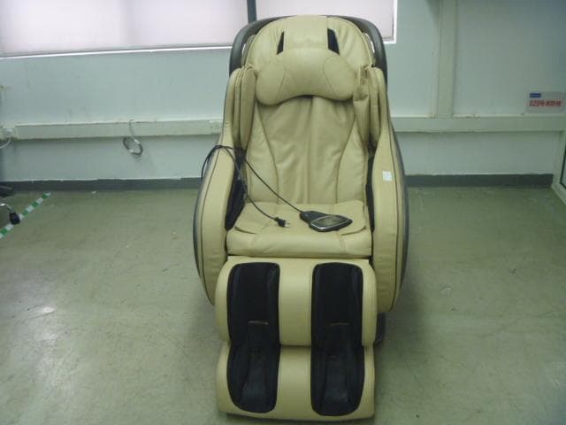
2ADIW-HL8800
Jan 04, 2015HL-8800
Equipment Class
DSS - Part 15 Spread Spectrum Transmitter