2ADRG-BRY703Bluetooth Keyboard
BRYDGE GLOBAL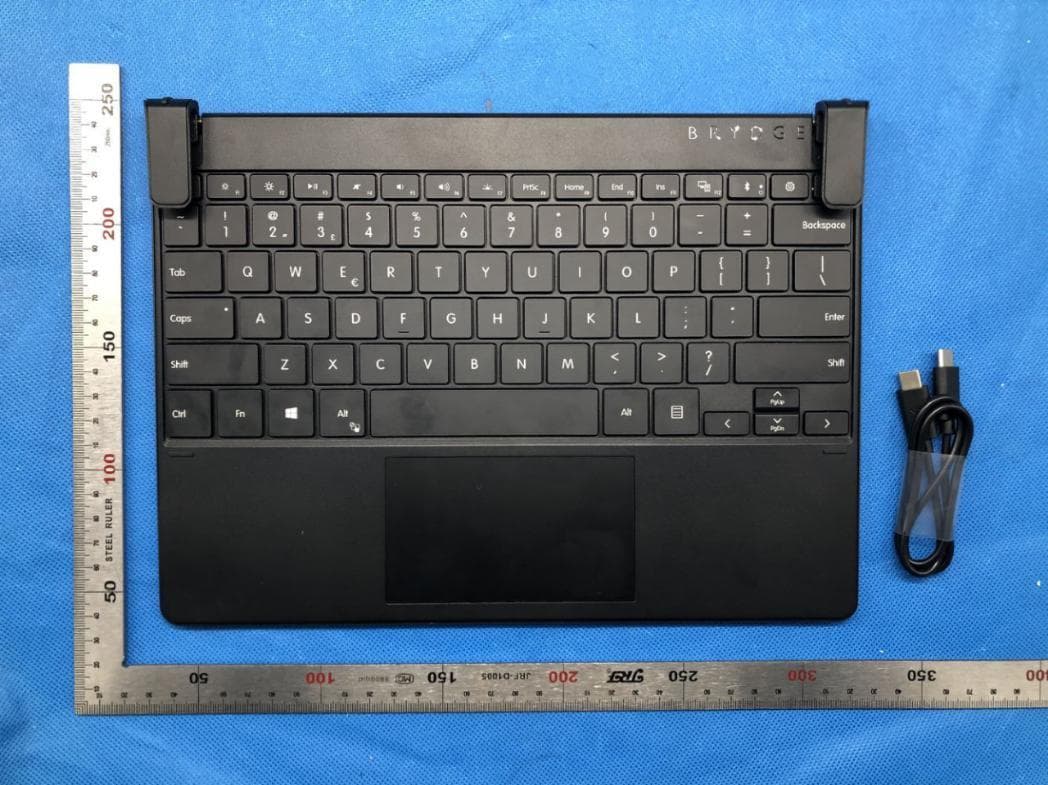
Click to zoom
Application Details
- Equipment Class
- DTS - Digital Transmission System
- Date of Grant
- Dec 29, 2020
- Application Purpose
- Original Equipment
- Date of Application
- Dec 29, 2020
- Equipment Note
- Bluetooth Keyboard
- Frequency Range
- 2402.00000000 - 2480.00000000
- Company
- BRYDGE GLOBAL
- Country
- United States
Documents & Files
Document Text
Text extracted from the exhibit documents filed with the FCC. Open a document above to read the original.
Users Manual
Brydge SPX+ User Manual Mode d’emploi INSERT/REMOVE POWER PAIR CHARGE TO INSERT: Place your Brydge on a flat surface and set the hinges upright to 90 degrees. Insert your Surface Pro X into the hinges, one side at a time, with the Wake and Volume Buttons on top. TO REMOVE: Ensure your Brydge is on a flat surface. Place your hand towards the back of the keyboard and pull up on your Surface Pro X, one side at a time. To manually power on, press and hold Fn + Bluetooth keys. The light will turn green for 2 seconds to indicate power. To manually power off, press and hold Fn + Bluetooth keys for 2 seconds. The light will blink red momentarily to indicate it’s powered off. TO CHECK BATTERY LIFE: go to Windows > Settings > Devices > Bluetooth & other devices, and check the battery level on ‘Brydge SPX+’. NOTE: If battery life is below 15%, the backlit key functionality will be disabled to conserve remaining battery life and the light on the Delete key will blink red. TO CHARGE: Insert the charging cable into the keyboard and plug the other end into a power source. A solid red LED on the Bluetooth key indicates the Brydge is charging. When the keyboard is fully charged, the red LED will turn off. A full charge can take up to three hours. 1. Turn on your Brydge SPX+ (Fn+Bluetooth), then press and hold the Bluetooth key for three seconds. The Bluetooth key light will flash blue confirming your Brydge is in pairing mode. 3. Type in the PIN on your Brydge SPX+ and hit Enter. 2. On your Surface Pro X, select: • Start • Settings • Devices • Bluetooth & other devices • Add Bluetooth or other device • Bluetooth • Brydge SPX+ NOTE: If pairing takes longer than three minutes, the blue light will stop flashing and you will need to press the Bluetooth button again. SLEEP/WAKE To conserve battery, your Brydge will enter sleep mode after 15 minutes of non-use. Press any key to wake it. When you close your devices together, your Brydge will put your Surface Pro X into sleep mode. When you open your devices, your Brydge will wake your Surface Pro X. NOTE: Your Brydge will not put your Surface Pro X to sleep or wake it after 15 minutes of non-use. PRECISION TOUCHPAD KEYBOARD SHORTCUTS Touchpad Disable/Enable Fn + Alt (Hold Fn & tap Alt to disable. Hold Fn & tap Alt again to enable.) Help Fn + F1 Copy Ctrl + C Cut Ctrl + X Paste Ctrl + V Underline Ctrl + U Italic Ctrl + I Undo Ctrl + Z Task View Alt + Tab Page Up Fn + Up Arrow Page Down Fn + Down Arrow Home Fn + Left Arrow End Fn + Right Arrow Thank you for purchasing a Brydge product. This product comes with a 1-year limited hardware warranty on the terms and conditions set out in this document and at www.brydge.com/warranty. All Brydge warranties are non- transferrable and are only available to the original end-user of the product. Warranties do not apply to products purchased from online vendors unauthorized to sell Brydge-branded product. If a defect arises during the warranty period, cease using the product and contact Brydge. To obtain warranty service, visit www.brydge.com/support or call +1 (435) 604-0481. Brydge, at its sole discretion and option, will (1) repair the product at no charge using new parts or parts that are equivalent to new in performance and reliability, or (2) replace or exchange the product with a product of equivalent functionality and value. Brydge offers free return shipping on any approved warranty claims. A shipping label will be provided to you if you are within the United States. If you are outside the United States, Brydge will reimburse your return shipping to a maximum of US$15.00 after providing a copy of the shipping receipt. Australia Only: Our goods come with guarantees that cannot be excluded under the Australian Consumer Law. You are entitled to a replacement or refund for a major failure and compensation for any other reasonably foreseeable loss or damage. You are also entitled to have the goods repaired or replaced if the goods fail to be of acceptable quality and the failure does not amount to a major failure. Brydge Technologies LLC | 1912 Sidewinder Dr., Suite 104, Park City, UT 84060 USA HAVE A QUESTION? Visit www.brydge.com/support WARRANTY The Brydge SPX+ touchpad pairs with your Windows device as a Precision Touchpad, and therefore utilizes all of the Windows touchpad gesture capabilities. To adjust the settings and gestures of your touchpad, select Start > Settings > Devices > Touchpad. The Touchpad can be turned on and off by pressing Fn + Alt. Language Switch Win + Spacebar (Use spacebar to toggle through available languages.) Scroll 2 finger swipe (up, down, left, right) Left Click | Click on left side of touchpad or 1 finger tap Right Click | Click on right side of touchpad or 2 finger tap Zoom Out 2 finger pinch Zoom In 2 finger stretch Open Action Center 4 finger tap Switch Virtual Desktop 4 finger swipe (left or right) Open Cortana 3 finger tap Show Desktop 3 finger swipe down See Open Windows 3 finger swipe up Task View 3 finger swipe (left or right) Function Lock Fn + Esc / Fn Lock (Hold Fn & tap Esc / Fn Lock to enable and disable function lock.) INSÉRER / RETIRER MISE EN MARCHE APPAIRER CHARGE INSÉRER : Placez votre Brydge sur une surface plane et réglez les charnières à 90 degrés. Insérez votre Surface Pro X dans les charnières, un côté à la fois, avec les boutons de Réveil et de Volume positionnés sur le dessus. RETIRER : Assurez-vous que votre Brydge est sur une surface plane. Placez votre main vers l’arrière du clavier et tirez sur votre Surface Pro, un côté à la fois. Pour allumer manuellement, maintenez enfoncées les touches Fn + Bluetooth Le voyant deviendra vert pendant 2 secondes pour indiquer la mise en marche. Pour éteindre manuellement, maintenez enfoncées les touches Fn + Bluetooth pendant 2 secondes. Le voyant clignotera momentanément en rouge pour indiquer la mise hors tension. POUR VÉRIFIER LA DURÉE DE VIE DE LA BATTERIE : accédez à Windows > Paramètres > Appareils > Bluetooth et autr…
Text truncated - open the document above for the full version.
Cover Letter(s)
BRYDGE GLOBAL 1912 Sidewinder Dr#104, Park City, Utah 84060, United States Agent Authorization Company: BRYDGE GLOBAL Address: 1912 Sidewinder Dr#104, Park City, Utah 84060, United States Product Name: Brydge SPX+ Model Number(s): BRY703 Product Description: Bluetooth Keyboard We authorize MiCOM Labs Inc., 575 Boulder Court, Pleasanton, California 94566, USA, to act on our behalf on all matters concerning the certification of above named equipment. We declare that MiCOM Labs Inc. is allowed to forward all information related to the approval and certification of equipment to the regulatory agencies as required and to discuss any issues concerning the approval application. Any and all acts carried out by MiCOM Labs on our behalf shall have the same effect as acts of our own. Signature: Date: Nov. 25, 2020 Name: Nicholas Smith Title: CEO Company: BRYDGE GLOBAL
Cover Letter(s)
BRYDGEGLOBAL 1912SidewinderDr#104,ParkCity,Utah84060,UnitedStates OfficeofEngineeringTechnology FederalCommunicationsCommission 7435OaklandMillsRoad Columbia,MD21046 USA Date:Nov.25,2020 Subject;RequestforConfidentiality FCCID:2ADRG-BRY703 ToWhomItMayConcern, PursuanttotheprovisionsoftheCommission’srulesTitle47Sections§0.457and§0.459,we arerequestingtheCommissiontowithholdthefollowingattachment(s)asconfidential documentsfrompublicdisclosureindefinitely. Thesedocumentscontaindetailedsystemandequipmentdescriptionsandareconsideredas proprietaryinformationinoperationoftheequipment.Thepublicdisclosureofthesedocuments mightbeharmfultoourcompanyandwouldgivecompetitorsanunfairadvantageinthemarket. SchematicDiagram BlockDiagram OperationalDescription Itisourunderstandingthatallmeasurementtestreports,FCCIDlabelformatand correspondenceduringthecertificationreviewprocesscannotbegrantedasconfidential documentsandthisinformationwillbeavailableforpublicreviewoncethegrantofequipment authorizationisissued. Sincerely, Signature: Name:NicholasSmith Title:CEO
External Photos
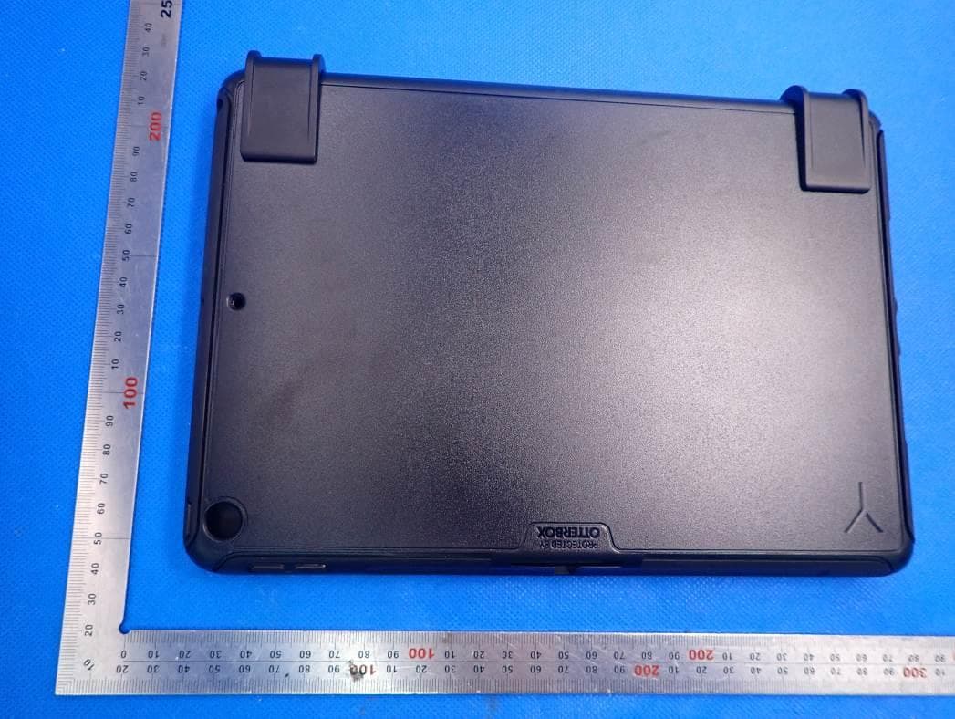
External Photos ALL VIEW-1 OF EUT EXTERNAL VIEW-1 OF EUT EXTERNAL VIEW-2 OF EUT EXTERNAL VIEW-3 OF EUT EXTERNAL VIEW-4 OF EUT EXTERNAL VIEW-5 OF EUT EXTERNAL VIEW-6 OF EUT EXTERNAL VIEW-7 OF EUT
ID Label/Location Info
FCC ID and IC Label Location 50mm*10mm
Internal Photos
Internal Photos INTERNAL VIEW-1 OF EUT INTERNAL VIEW-2 OF EUT INTERNAL VIEW-3 OF EUT INTERNAL VIEW-4 OF EUT Antenna INTERNAL VIEW-5 OF EUT INTERNAL VIEW-6 OF EUT INTERNAL VIEW-7 OF EUT
RF Exposure Info
RF EXPOSURE EVALUATION 1. PRODUCT INFORMATION Product Description Brydge SPX+ Model Name BRY703 FCC ID 2ADRG-BRY703 2. EVALUATION METHOD According to 447498 D01 General RF Exposure Guidance v05 The 1-g and 10-g SAR test exclusion thresholds for 100 MHz to 6 GHz at test separation distances ≤ 50 mm are determined by: [(max. power of channel, including tune-up tolerance, mW)/(min. test separation distance, mm)] ·[√f(GHz)] ≤ 3.0 for 1-g SAR and ≤ 7.5 for 10-g extremity SAR. Where f(GHz) is the RF channel transmit frequency in GHz Power and distance are rounded to the nearest mW and mm before calculation 3. CALCULATION BLE: P t = 0.315dBm=1.08mW The value of the Maximum output power P t is referred to the test report of the CFR47 §15.247. The result for RF exposure evaluation SAR=(1.08mW /5mm) .[√2.402GHz)]= 0.33<3.0 for 1-g SAR and ≤ 7.5 for 10-g extremity SAR. 4. CONCLUSION The SAR evaluation is not required.
Test Report
Page 1 of 52 FCC Test Report Report No.: AGC05764201101FE02 FCC ID : 2ADRG-BRY703 APPLICATION PURPOSE : Original Equipment PRODUCT DESIGNATION : Brydge SPX+ BRAND NAME : BRYDGE MODEL NAME : BRY703 APPLICANT : BRYDGE GLOBAL DATE OF ISSUE : Nov. 24, 2020 STANDARD(S) : FCC Part 15.247 REPORT VERSION : V1.0 Attestation of Global Compliance (Shenzhen) Co., Ltd Report No.: AGC05764201101FE02 Page 2 of 52 REPORT REVISE RECORD Report Version Revise Time Issued Date Valid Version Notes V1.0 / Nov. 24, 2020 Valid Initial Release Report No.: AGC05764201101FE02 Page 3 of 52 TABLE OF CONTENTS 1. VERIFICATION OF COMPLIANCE .................................................................................................................. 5 2. GENERAL INFORMATION .............................................................................................................................. 6 2.1. PRODUCT DESCRIPTION ........................................................................................................................ 6 2.2. TABLE OF CARRIER FREQUENCYS ....................................................................................................... 6 2.3. RELATED SUBMITTAL(S)/GRANT(S) ....................................................................................................... 7 2.4. TEST METHODOLOGY ............................................................................................................................. 7 2.5. SPECIAL ACCESSORIES .......................................................................................................................... 7 2.6. EQUIPMENT MODIFICATIONS ................................................................................................................. 7 2.7. ANTENNA REQUIREMENT ....................................................................................................................... 7 3. MEASUREMENT UNCERTAINTY ................................................................................................................... 8 4. DESCRIPTION OF TEST MODES ................................................................................................................... 9 5. SYSTEM TEST CONFIGURATION ................................................................................................................ 10 5.1. CONFIGURATION OF TESTED SYSTEM ............................................................................................... 10 5.2. EQUIPMENT USED IN TESTED SYSTEM .............................................................................................. 10 5.3. SUMMARY OF TEST RESULTS .............................................................................................................. 10 6. TEST FACILITY .............................................................................................................................................. 11 7. PEAK OUTPUT POWER ................................................................................................................................ 12 7.1. MEASUREMENT PROCEDURE .............................................................................................................. 12 7.2. TEST SET-UP (BLOCK DIAGRAM OF CONFIGURATION) .................................................................... 12 7.3. LIMITS AND MEASUREMENT RESULT .................................................................................................. 13 8. 6 DB BANDWIDTH ......................................................................................................................................... 15 8.1. MEASUREMENT PROCEDURE .............................................................................................................. 15 8.2. TEST SET-UP (BLOCK DIAGRAM OF CONFIGURATION) .................................................................... 15 8.3. LIMITS AND MEASUREMENT RESULTS ............................................................................................... 15 9. CONDUCTED SPURIOUS EMISSION........................................................................................................... 17 9.1. MEASUREMENT PROCEDURE .............................................................................................................. 17 9.2. TEST SET-UP (BLOCK DIAGRAM OF CONFIGURATION) .................................................................... 17 9.3. MEASUREMENT EQUIPMENT USED .................................................................................................... 17 9.4. LIMITS AND MEASUREMENT RESULT .................................................................................................. 17 10. MAXIMUM CONDUCTED OUTPUT POWER SPECTRAL DENSITY ........................................................ 25 Report No.: AGC05764201101FE02 Page 4 of 52 10.1. MEASUREMENT PROCEDURE ............................................................................................................ 25 10.2. TEST SET-UP (BLOCK DIAGRAM OF CONFIGURATION) .................................................................. 25 10.3. MEASUREMENT EQUIPMENT USED .................................................................................................. 25 10.4. LIMITS AND MEASUREMENT RESULT................................................................................................ 25 11. RADIATED EMISSION ................................................................................................................................. 27 11.1. MEASUREMENT PROCEDURE ............................................................................................................ 27 11.2. TEST SETUP .......................................................................................................................................... 28 11.3. LIMITS AND MEASUREMENT RESULT................................................................................................ 29 11.4. TEST RESULT …
Text truncated - open the document above for the full version.
Test Report
Report No.: AGC05764201101FE02 Page 31 of 52 EUT Brydge SPX+ Model Name BRY703 Temperature 25°C Relative Humidity 55.4% Pressure 960hPa Test Voltage Normal Voltage Test Mode Mode 1 Antenna Vertical RESULT: PASS Note: 1. Factor=Antenna Factor + Cable loss, Margin=Measurement-Limit. 2. All test modes had been tested. The mode 1 is the worst case and recorded in the report. Report No.: AGC05764201101FE02 Page 32 of 52 RADIATED EMISSION ABOVE 1GHZ EUT Brydge SPX+ Model Name BRY703 Temperature 25°C Relative Humidity 55.4% Pressure 960hPa Test Voltage Normal Voltage Test Mode Mode 1 Antenna Horizontal FrequencyMeter ReadingFactorEmission LevelLimitsMargin (MHz)(dBμV)(dB)(dBμV/m)(dBμV/m)(dB) 4804.00044.330.0844.4174-29.59 peak 4804.00035.610.0835.6954-18.31 AVG 7206.00038.572.2140.7874-33.22 peak 7206.00032.482.2134.6954-19.31 AVG Remark: Factor = Antenna Factor + Cable Loss – Pre-amplifier. Value Type EUT Brydge SPX+ Model Name BRY703 Temperature 25°C Relative Humidity 55.4% Pressure 960hPa Test Voltage Normal Voltage Test Mode Mode 1 Antenna Vertical FrequencyMeter ReadingFactorEmission LevelLimitsMargin (MHz)(dBμV)(dB)(dBμV/m)(dBμV/m)(dB) 4804.00044.940.0845.0274-28.98 peak 4804.00036.140.0836.2254-17.78 AVG 7206.00038.862.2141.0774-32.93 peak 7206.00033.152.2135.3654-18.64 AVG Remark: Factor = Antenna Factor + Cable Loss – Pre-amplifier. Value Type Report No.: AGC05764201101FE02 Page 33 of 52 EUT Brydge SPX+ Model Name BRY703 Temperature 25°C Relative Humidity 55.4% Pressure 960hPa Test Voltage Normal Voltage Test Mode Mode 2 Antenna Horizontal FrequencyMeter ReadingFactorEmission LevelLimitsMargin (MHz)(dBμV)(dB)(dBμV/m)(dBμV/m)(dB) 4880.00044.290.1444.4374-29.57 peak 4880.00035.740.1435.8854-18.12 AVG 7320.00039.252.3641.6174-32.39 peak 7320.00032.162.3634.5254-19.48 AVG Remark: Factor = Antenna Factor + Cable Loss – Pre-amplifier. Value Type EUT Brydge SPX+ Model Name BRY703 Temperature 25°C Relative Humidity 55.4% Pressure 960hPa Test Voltage Normal Voltage Test Mode Mode 2 Antenna Vertical FrequencyMeter ReadingFactorEmission LevelLimitsMargin (MHz)(dBμV)(dB)(dBμV/m)(dBμV/m)(dB) 4880.00046.210.1446.3574-27.65 peak 4880.00038.720.1438.8654-15.14 AVG 7320.00040.662.3643.0274-30.98 peak 7320.00033.322.3635.6854-18.32 AVG Remark: Factor = Antenna Factor + Cable Loss – Pre-amplifier. Value Type Report No.: AGC05764201101FE02 Page 34 of 52 EUT Brydge SPX+ Model Name BRY703 Temperature 25°C Relative Humidity 55.4% Pressure 960hPa Test Voltage Normal Voltage Test Mode Mode 3 Antenna Horizontal FrequencyMeter ReadingFactorEmission LevelLimitsMargin (MHz)(dBμV)(dB)(dBμV/m)(dBμV/m)(dB) 4960.00044.340.2244.5674-29.44 peak 4960.00036.210.2236.4354-17.57 AVG 7440.00038.492.6441.1374-32.87 peak 7440.00029.452.6432.0954-21.91 AVG Remark: Factor = Antenna Factor + Cable Loss – Pre-amplifier. Value Type EUT Brydge SPX+ Model Name BRY703 Temperature 25°C Relative Humidity 55.4% Pressure 960hPa Test Voltage Normal Voltage Test Mode Mode 3 Antenna Vertical FrequencyMeter ReadingFactorEmission LevelLimitsMargin (MHz)(dBμV)(dB)(dBμV/m)(dBμV/m)(dB) 4960.00042.640.2242.8674-31.14 peak 4960.00034.270.2234.4954-19.51 AVG 7440.00038.052.6440.6974-33.31 peak 7440.00029.992.6432.6354-21.37 AVG Remark: Factor = Antenna Factor + Cable Loss – Pre-amplifier. Value Type RESULT: PASS Note: The amplitude of other spurious emissions from 1G to 25 GHz which are attenuated more than 20 dB below the permissible value need not be reported. Factor = Antenna Factor + Cable loss - Amplifier gain, Over=Measure-Limit. The “Factor” value can be calculated automatically by software of measurement system. Report No.: AGC05764201101FE02 Page 35 of 52 TEST RESULT FOR RESTRICTED BANDS REQUIREMENTS EUT Brydge SPX+ Model Name BRY703 Temperature 25°C Relative Humidity 55.4% Pressure 960hPa Test Voltage Normal Voltage Test Mode Mode 1 Antenna Horizontal PK AV RESULT: PASS Report No.: AGC05764201101FE02 Page 36 of 52 EUT Brydge SPX+ Model Name BRY703 Temperature 25°C Relative Humidity 55.4% Pressure 960hPa Test Voltage Normal Voltage Test Mode Mode 1 Antenna Vertical PK AV RESULT: PASS Report No.: AGC05764201101FE02 Page 37 of 52 EUT Brydge SPX+ Model Name BRY703 Temperature 25°C Relative Humidity 55.4% Pressure 960hPa Test Voltage Normal Voltage Test Mode Mode 3 Antenna Horizontal PK AV RESULT: PASS Report No.: AGC05764201101FE02 Page 38 of 52 EUT Brydge SPX+ Model Name BRY703 Temperature 25°C Relative Humidity 55.4% Pressure 960hPa Test Voltage Normal Voltage Test Mode Mode 3 Antenna Vertical PK AV RESULT: PASS Note: The factor had been edited in the “Input Correction” of the Spectrum Analyzer. Report No.: AGC05764201101FE02 Page 39 of 52 12. FCC LINE CONDUCTED EMISSION TEST 12.1. LIMITS OF LINE CONDUCTED EMISSION TEST Frequency Maximum RF Line Voltage Q.P.( dBuV) Average( dBuV) 150kHz~500kHz 66-56 56-46 500kHz~5MHz 56 46 5MHz~30MHz 60 50 Note: 1. The lower limit shall apply at the transition frequency. 2. The limit decreases linearly with the logarithm of the frequency in the range 0.15 MHz to 0.50 MHz. 12.2. BLOCK DIAGRAM OF LINE CONDUCTED EMISSION TEST EUT & Support Units Report No.: AGC05764201101FE02 Page 40 of 52 12.3. PRELIMINARY PROCEDURE OF LINE CONDUCTED EMISSION TEST 1. The equipment was set up as per the test configuration to simulate typical actual usage per the user’s manual. When the EUT is a tabletop system, a wooden table with a height of 0.8 meters is used and is placed on the ground plane as per ANSI C63.10 (see Test Facility for the dimensions of the ground plane used). When the EUT is a floor-standing equipment, it is placed on the ground plane which has a 3-12 mm non-conductive covering to insulate the EUT from the ground plane. 2. Support equipment, if needed, was placed as per ANSI C63.10. 3. All I/O cables were positioned to simulate typical actual usage as per ANSI C63.10. 4. All support equipment received AC120V/60Hz power from a LISN, if any. 5. The EUT received DC 5V power from adapter which received AC120V/60Hz…
Text truncated - open the document above for the full version.
Test Setup Photos
Test Setup Photos RADIATED EMISSION TEST SETUP BELOW 1GHZ RADIATED EMISSION TEST SETUP ABOVE 1GHZ LINE CONDUCTED EMISSION TEST SETUP CONDUCTED TEST SETUP
Contact Information
Applicant
Nicholas Smith
Technical Contact
Test Firm
Attestation of Global Compliance (Shenzhen) Co., LDoris Li
[email protected]+86-755-25234088
Technical Specifications
| # | Rule Parts | Frequency Range | Power Output |
|---|---|---|---|
| 1 | 15C | 2.40 GHz - 2.48 GHz | 1.10 mW |
Other Applications from BRYDGE GLOBAL
2ADRG-BRY801K
Feb 28, 2021Bluetooth Wireless keyboard
Equipment Class
DXX - Part 15 Low Power Communication Device Transmitter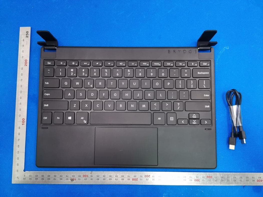
2ADRG-BRY7011
Aug 25, 2020Bluetooth Keyboard
Equipment Class
DXX - Part 15 Low Power Communication Device Transmitter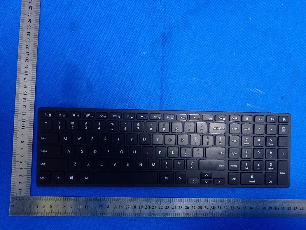
2ADRG-BRY7301
Aug 23, 2020Bluetooth keyboard
Equipment Class
DTS - Digital Transmission System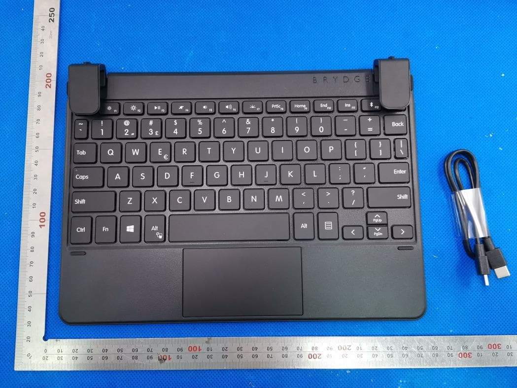
2ADRG-BRY702
Aug 23, 2020Bluetooth Keyboard
Equipment Class
DXX - Part 15 Low Power Communication Device Transmitter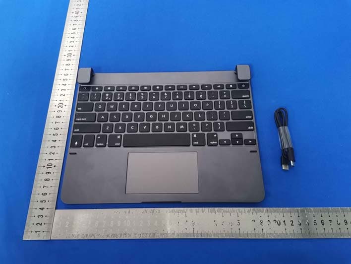
2ADRG-BRYTP602N
Jul 23, 2020Bluetooth Keyboard
Equipment Class
DTS - Digital Transmission System