2ADRG-BRY801KBluetooth Wireless keyboard
BRYDGE GLOBAL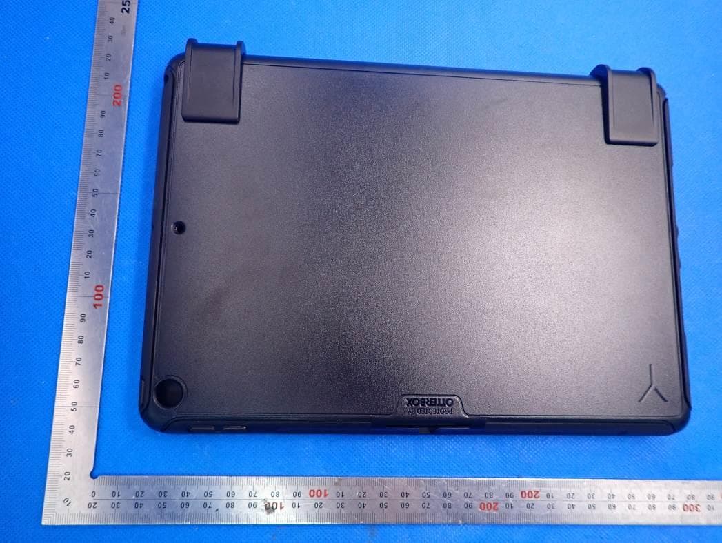
Click to zoom
Application Details
- Equipment Class
- DXX - Part 15 Low Power Communication Device Transmitter
- Date of Grant
- Feb 28, 2021
- Application Purpose
- Original Equipment
- Date of Application
- Feb 28, 2021
- Equipment Note
- Bluetooth Wireless keyboard
- Frequency Range
- 2402.00000000 - 2480.00000000
- Company
- BRYDGE GLOBAL
- Country
- United States
Documents & Files
Document Text
Text extracted from the exhibit documents filed with the FCC. Open a document above to read the original.
Users Manual
10.2 MAX+ User Manual Mode d’emploi Bluetooth Wireless keyboard BRYDGE BRY801 FCC ID:2ADRG-BRY801K IC:24378-BRY801K TO TURN ON: Press the power key for one second until the LED flashes green. TO TURN OFF: Press and hold the power key for three seconds until the LED flashes red. NOTE: To conserve battery, your Brydge will enter sleep mode after 20 minutes of non-use. Press any key to turn back on. Your Brydge will enter sleep mode when both devices are closed like a laptop. TO PAIR: Press and hold the Bluetooth TM key for three seconds until the LED flashes blue. On your iPad, under Settings > Bluetooth TM select Brydge 10.2 MAX+. When successfully paired, the blue LED will turn off and your keyboard and trackpad will be active. POWER PAIR CUSTOMIZE THE TRACKPAD For up-to-date settings and video instructions, visit: www.brydge.com/102-max-plus-instructions ATTACH PROTECTIVE CASE UPDATE FIRMWARE Download Brydge Connect from the App Store for the latest firmware updates. REMOVE PROTECTIVE CASE Brydge 10.2 MAX+ User Manual TO CHECK BATTERY LIFE: In Today View, go to the BATTERIES section to check battery life. If not available, swipe left on your Home Screen to show Today View, scroll to the bottom and click edit. Scroll down to Batteries, and click the green ‘+’ icon to add. NOTE: If battery life is below 15%, backlit key functionality will be disabled to conserve battery. TO CHARGE: Insert the charging cable into the keyboard and plug the other end into a power source. A solid red LED indicates the Brydge is charging. When the keyboard is fully charged, the red LED will turn off. A full charge can take up to three hours. Thank you for purchasing a Brydge product. This product comes with a 1-year limited hardware warranty on the terms and conditions set out in this document and at www.brydge.com/warranty. All Brydge warranties are non- transferrable and are only available to the original end-user of the product. Warranties do not apply to products purchased from online vendors unauthorized to sell Brydge-branded product. If a defect arises during the warranty period, cease using the product and contact Brydge. To obtain warranty service, visit www.brydge.com/support or call +1 (435) 604-0481. Brydge, at its sole discretion and option, will (1) repair the product at no charge using new parts or parts that are equivalent to new in performance and reliability, or (2) replace or exchange the product with a product of equivalent functionality and value. Brydge offers free return shipping on any approved warranty claims. A shipping label will be provided to you if you are within the United States. If you are outside the United States, Brydge will reimburse your return shipping to a maximum of US$15.00 after providing a copy of the shipping receipt. Australia Only: Our goods come with guarantees that cannot be excluded under the Australian Consumer Law. You are entitled to a replacement or refund for a major failure and compensation for any other reasonably foreseeable loss or damage. You are also entitled to have the goods repaired or replaced if the goods fail to be of acceptable quality and the failure does not amount to a major failure. Brydge Technologies LLC | 1912 Sidewinder Dr., Suite 104, Park City, UT 84060 USA HAVE A QUESTION? Visit www.brydge.com/support CHARGE KEYBOARD SHORTCUTS WARRANTY Copy Command + C Paste Command + V Cut Command + X Underline Command + U Italic Command + I Home Screen Command + H Switch App Command + Tab Show Dock Command + Option + D Search Command + Space Undo Command + Z Switch Language Ctrl + Shift + Spacebar (Spacebar allows you to toggle through available languages) IMPORTANT Before attaching your keyboard, ensure your iPad is inserted into the supplied protective case. INSERT/REMOVE KEYBOARD BEFORE INSERTING: Place your Brydge on a flat surface and set the hinges upright to 90 degrees. TO INSERT: Insert your iPad (in protective case) into the hinges with the home button on the left. TO REMOVE: Place your Brydge on a flat surface. Place your hand towards the back of the keyboard and pull up. POUR ALLUMER : maintenez la touche marche/arrêt enfoncée pendant une seconde jusqu’à ce que la DEL clignote verte. POUR ÉTEINDRE : maintenez la touche marche/arrêt enfoncée pendant trois secondes jusqu’à ce que la DEL clignote rouge. REMARQUE : pour préserver la charge de la batterie, votre pavé tactile sans fil Brydge entrera en mode veille après 20 minutes d’inactivité. Votre pavé tactile sans fil Brydge entrera en mode veille lorsque les deux appareils sont fermés, comme un ordinateur portable. POUR JUMELER : maintenez la touche Bluetooth TM enfoncée pendant 3 secondes jusqu’à ce que la DEL bleue clignote. Sur votre iPad, sous Paramètres > Bluetooth TM , sélectionnez Brydge 10.2 MAX+. Une fois le couplage réussi, la DEL bleue s’éteindra et votre clavier et pavé tactile seront actifs. Pour des paramètres et des instructions vidéo à jour, visitez : www.brydge.com/102-max-plus-instructions ALIMENTATION JUMELER PERSONNALISER LE PAVÉ TACTILE Brydge 10.2 MAX+ Mode d’emploi Téléchargez Brydge Connect depuis l’App Store pour les dernières mises à jour du firmware. MISE À JOUR DU FIRMWARE INSÉRER L’ÉTUI DE PROTECTION RETIRER L’ÉTUI DE PROTECTION CHARGER RACCOURCIS CLAVIER GARANTIE POUR VÉRIFIER LA DURÉE DE VIE DE LA BATTERIE : Dans l’affichage d’aujourd’hui, accéder à la section BATTERIES pour vérifier la durée de vie de la batterie. S’il n’est pas disponible, balayer vers la gauche sur votre Écran d’accueil pour afficher l’Affichage d’aujourd’hui, faites défiler vers le bas et cliquez sur Modifier. Faites défiler vers le bas jusqu’à Batteries et cliquez sur l’icône verte ‘+’ pour ajouter. REMARQUE : lorsque la batterie est inférieure à 15%, la fonction de rétro-éclairage des touches sera désactivé pour préserver la charge de la batterie. POUR CHARGER : insérez le câble de chargement dans le clavier et branchez l’autre extrémité dans une prise de courant. Un voyant lumineux r…
Text truncated - open the document above for the full version.
Cover Letter(s)
BRYDGE GLOBAL 1912 Sidewinder Dr#104, Park City, Utah 84060, United States Agent Authorization Company: BRYDGE GLOBAL Address: 1912 Sidewinder Dr#104, Park City, Utah 84060, United States Product Name: Bluetooth Wireless keyboard Model Number(s): BRY801 Product Description: Bluetooth Wireless keyboard We authorize MiCOM Labs Inc., 575 Boulder Court, Pleasanton, California 94566, USA, to act on our behalf on all matters concerning the certification of above named equipment. We declare that MiCOM Labs Inc. is allowed to forward all information related to the approval and certification of equipment to the regulatory agencies as required and to discuss any issues concerning the approval application. Any and all acts carried out by MiCOM Labs on our behalf shall have the same effect as acts of our own. Signature: Date: Nov. 27, 2020 Name: Nicholas Smith Title: CEO Company: BRYDGE GLOBAL
Cover Letter(s)
BRYDGE GLOBAL 1912 Sidewinder Dr#104, Park City, Utah 84060, United States Office of Engineering Technology Federal Communications Commission 7435 Oakland Mills Road Columbia, MD 21046 USA Date: Nov. 27, 2020 Subject; Request for Confidentiality FCC ID: 2ADRG-BRY801K To Whom It May Concern, Pursuant to the provisions of the Commission’s rules Title 47 Sections §0.457 and §0.459, we are requesting the Commission to withhold the following attachment(s) as confidential documents from public disclosure indefinitely. These documents contain detailed system and equipment descriptions and are considered as proprietary information in operation of the equipment. The public disclosure of these documents might be harmful to our company and would give competitors an unfair advantage in the market. Schematic Diagram Block Diagram Operational Description It is our understanding that all measurement test reports, FCC ID label format and correspondence during the certification review process cannot be granted as confidential documents and this information will be available for public review once the grant of equipment authorization is issued. Sincerely, Signature: Name: Nicholas Smith Title: CEO
External Photos
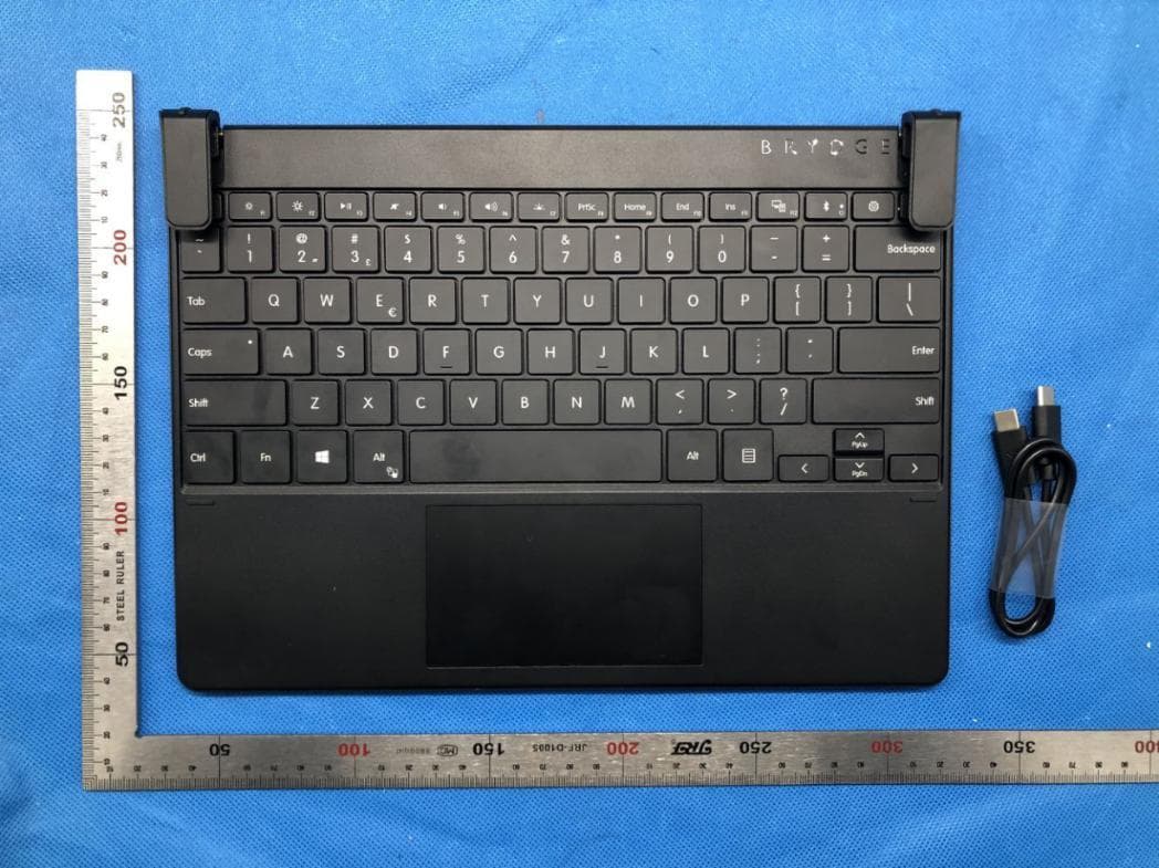
External Photos TOP VIEW OF EUT BOTTOM VIEW OF EUT FRONT VIEW OF EUT BACK VIEW OF EUT LEFT VIEW OF EUT RIGHT VIEW OF EUT VIEW OF EUT(PORT)
ID Label/Location Info
FCC ID and IC Label Location 45mm*20mm FCC ID: 2ADRG-BRY801K IC: 24378-BRY801K BRY801
Internal Photos
Internal Photos OPEN VIEW OF EUT-1 OPEN VIEW OF EUT-2 VIEW OF BATTERY INTERNAL VIEW OF EUT-1 BT Antenna INTERNAL VIEW OF EUT-2 INTERNAL VIEW OF EUT-3 INTERNAL VIEW OF EUT-4 INTERNAL VIEW OF EUT-5 INTERNAL VIEW OF EUT-6
RF Exposure Info
Page 1 of 35 SAR Test Report Report No.: AGC11575201101FH01 FCC ID : 2ADRG-BRY801K APPLICATION PURPOSE : Original Equipment PRODUCT DESIGNATION : Bluetooth Wireless keyboard BRAND NAME : BRYDGE MODEL NAME : BRY801 APPLICANT : BRYDGE GLOBAL DATE OF ISSUE : Dec. 24,2020 STANDARD(S) : IEEE Std. 1528:2013 FCC 47 CFR Part 2§2.1093:2013 IEEE Std C95.1 ™-2005 IEC 62209-1: 2016 REPORT VERSION : V1.0 Attestation of Global Compliance(Shenzhen) Co., Ltd. Report No.: AGC11575201101FH01 Page 2 of 35 Report Revise Record Report Version Revise Time Issued Date Valid Version Notes V1.0 / Dec. 24,2020 Valid Initial Release Report No.: AGC11575201101FH01 Page 3 of 35 Test Report Certification Applicant Name BRYDGE GLOBAL Applicant Address 1912 Sidewinder Dr#104, Park City, Utah 84060, United States Manufacturer Name BRYDGE GLOBAL Manufacturer Address 1912 Sidewinder Dr#104, Park City, Utah 84060, United States Factory Name Shenzhen Doking Technology Co., Ltd Factory Address Tower A, Building 16, Shapuwei Venture Industrial Zone, Songgang Street, Baoan District, Shenzhen, Guangdong Province, China Product Designation Bluetooth Wireless keyboard Brand Name BRYDGE Model Name BRY801 EUT Voltage DC3.7V by battery Applicable Standard IEEE Std. 1528:2013; FCC 47 CFR Part 2§2.1093:2013; IEEE Std C95.1 ™-2005; IEC 62209-1: 2016; Test Date Dec. 11,2020 Report Template AGCRT-US-Bluetooth/SAR (2018-01-01) Note: The results of testing in this report apply to the product/system which was tested only. Prepared By Thea Huang (Project Engineer) Dec. 11,2020 Reviewed By Angela Li (Reviewer) Dec. 24,2020 Approved By Forrest Lei (Authorized Officer) Dec. 24,2020 Report No.: AGC11575201101FH01 Page 4 of 35 TABLE OF CONTENTS 1. SUMMARY OF MAXIMUM SAR VALUE ......................................................................................................... 5 2. GENERAL INFORMATION ............................................................................................................................... 6 2.1. EUT DESCRIPTION......................................................................................................................................... 6 3. SAR MEASUREMENT SYSTEM ........................................................................................................................ 7 3.1. THE SATIMO SYSTEM USED FOR PERFORMING COMPLIANCE TESTS CONSISTS OF FOLLOWING ITEMS .................. 7 3.2. COMOSAR E-FIELD PROBE .......................................................................................................................... 8 3.3. ROBOT .......................................................................................................................................................... 8 3.4. VIDEO POSITIONING SYSTEM .......................................................................................................................... 9 3.5. DEVICE HOLDER ............................................................................................................................................ 9 3.6. SAM TWIN PHANTOM ................................................................................................................................... 10 4. SAR MEASUREMENT PROCEDURE .............................................................................................................. 11 4.1. SPECIFIC ABSORPTION RATE (SAR) .............................................................................................................. 11 4.2. SAR MEASUREMENT PROCEDURE ................................................................................................................ 12 4.3. RF EXPOSURE CONDITIONS ......................................................................................................................... 14 5. TISSUE SIMULATING LIQUID ......................................................................................................................... 15 5.1. THE COMPOSITION OF THE TISSUE SIMULATING LIQUID..................................................................................... 15 5.2. TISSUE DIELECTRIC PARAMETERS FOR HEAD AND BODY PHANTOMS ............................................................... 15 5.3. TISSUE CALIBRATION RESULT ....................................................................................................................... 16 6. SAR SYSTEM CHECK PROCEDURE ........................................................................................................... 17 6.1. SAR SYSTEM CHECK PROCEDURES ............................................................................................................. 17 6.2. SAR SYSTEM CHECK ................................................................................................................................... 18 7. EUT TEST POSITION ..................................................................................................................................... 19 7.1. BODY WORN POSITION ................................................................................................................................ 19 8. SAR EXPOSURE LIMITS ............................................................................................................................... 20 9. TEST FACILITY .............................................................................................................................................. 21 10. TEST EQUIPMENT LIST .............................................................................................................................. 22 11. MEASUREMENT UNCERTAINTY ................................................................................................................ 23 12. CONDUCTED POWER MEASUREMENT ..................................................................................................... 26 13. TEST RESULTS ....................................................................................…
Text truncated - open the document above for the full version.
RF Exposure Info
CALIBRATION DATA PROBE CALIBRATION DATA DIPOLE CALIBRATION DATA
Test Report
Page 1 of 42 FCC Test Report Report No.: AGC11575201101FE03 FCC ID : 2ADRG-BRY801K APPLICATION PURPOSE : Original Equipment PRODUCT DESIGNATION : Bluetooth Wireless keyboard BRAND NAME : BRYDGE MODEL NAME : BRY801 APPLICANT : BRYDGE GLOBAL DATE OF ISSUE : Nov. 26,2020 STANDARD(S) : FCC Part 15 Rules REPORT VERSION : V1.0 Attestation of Global Compliance (Shenzhen) Co., Ltd Report No.: AGC11575201101FE03 Page 2 of 42 REPORT REVISE RECORD Report Version Revise Time Issued Date Valid Version Notes V1.0 / Nov. 26,2020 Valid Initial release Report No.: AGC11575201101FE03 Page 3 of 42 TABLE OF CONTENTS 1. VERIFICATION OF CONFORMITY .................................................................................................................. 5 2. GENERAL INFORMATION .............................................................................................................................. 6 2.1. PRODUCT DESCRIPTION ........................................................................................................................ 6 2.2. TABLE OF CARRIER FREQUENCY .......................................................................................................... 6 3. MEASUREMENT UNCERTAINTY ................................................................................................................... 7 4. DESCRIPTION OF TEST MODES ................................................................................................................... 8 5. SYSTEM TEST CONFIGURATION .................................................................................................................. 9 5.1. CONFIGURATION OF EUT SYSTEM ........................................................................................................ 9 5.2 EQUIPMENT USED IN TESTED SYSTEM ................................................................................................. 9 5.3. SUMMARY OF TEST RESULTS ................................................................................................................ 9 6. TEST FACILITY .............................................................................................................................................. 10 7. RADIATED EMISSION ................................................................................................................................... 11 7.1TEST LIMIT ................................................................................................................................................ 11 7.2. MEASUREMENT PROCEDURE ............................................................................................................. 12 7.3. TEST SETUP............................................................................................................................................ 14 7.4. TEST RESULT .......................................................................................................................................... 15 8. BAND EDGE EMISSION ................................................................................................................................ 21 8.1TEST LIMIT ................................................................................................................................................ 21 8.2. MEASUREMENT PROCEDURE ............................................................................................................. 21 8.3 TEST SETUP............................................................................................................................................. 21 8.4 TEST RESULT ........................................................................................................................................... 22 9. 20DB BANDWIDTH ........................................................................................................................................ 26 9.1. MEASUREMENT PROCEDURE ............................................................................................................. 26 9.2. TEST SET-UP (BLOCK DIAGRAM OF CONFIGURATION) .................................................................... 26 9.3. MEASUREMENT RESULTS .................................................................................................................... 27 10. FCC LINE CONDUCTED EMISSION TEST ................................................................................................ 29 10.1. LIMITS OF LINE CONDUCTED EMISSION TEST ................................................................................ 29 10.2. BLOCK DIAGRAM OF LINE CONDUCTED EMISSION TEST .............................................................. 29 10.3. PRELIMINARY PROCEDURE OF LINE CONDUCTED EMISSION TEST ........................................... 30 Report No.: AGC11575201101FE03 Page 4 of 42 10.4. FINAL PROCEDURE OF LINE CONDUCTED EMISSION TEST .......................................................... 30 10.5. TEST RESULT OF LINE CONDUCTED EMISSION TEST .................................................................... 31 APPENDIX A: PHOTOGRAPHS OF TEST SETUP .......................................................................................... 33 APPENDIX B: PHOTOGRAPHS OF THE EUT ................................................................................................. 35 Report No.: AGC11575201101FE03 Page 5 of 42 1. VERIFICATION OF CONFORMITY Applicant BRYDGE GLOBAL Address 1912 Sidewinder Dr#104, Park City, Utah 84060, United States Manufacturer BRYDGE GLOBAL Address 1912 Sidewinder Dr#104, Park City, Utah 84060, United States Factory Shenzhen Doking Technology Co., Ltd Address Tower A, Building 16,Shapuwei Venture Industrial Zone, Songgang Street, Baoan District, Shenzhen, Guangdong Province, China Product Designation Bluetooth Wireless keyboard Brand Name BRYDGE Test Model BRY801 Date of test Nov. 18,2020 to Nov. 26,2020 Deviation No any deviation from the test method Condition of Test …
Text truncated - open the document above for the full version.
Test Report
Report No.: AGC11575201101FE03 Page 26 of 42 9. 20DB BANDWIDTH 9.1. MEASUREMENT PROCEDURE 1. Set the EUT Work on the top, the middle and the bottom operation frequency individually. 2. Set SPA Centre Frequency = Operation Frequency, RBW= 30 KHz, VBW≥3×RBW. 3. Set SPA Trace 1 Max hold, then View. 9.2. TEST SET-UP (BLOCK DIAGRAM OF CONFIGURATION) Report No.: AGC11575201101FE03 Page 27 of 42 9.3. MEASUREMENT RESULTS TEST ITEM 20DB BANDWIDTH TEST MODULATION GFSK 1M Test Data (MHz) Criteria Low Channel 1.123 PASS Middle Channel 1.124 PASS High Channel 1.124 PASS TEST PLOT OF BANDWIDTH FOR LOW CHANNEL Report No.: AGC11575201101FE03 Page 28 of 42 TEST PLOT OF BANDWIDTH FOR MIDDLE CHANNEL TEST PLOT OF BANDWIDTH FOR HIGH CHANNEL Report No.: AGC11575201101FE03 Page 29 of 42 10. FCC LINE CONDUCTED EMISSION TEST 10.1. LIMITS OF LINE CONDUCTED EMISSION TEST Frequency Maximum RF Line Voltage Q.P.( dBuV) Average( dBuV) 150kHz~500kHz 66-56 56-46 500kHz~5MHz 56 46 5MHz~30MHz 60 50 Note: 1. The lower limit shall apply at the transition frequency. 2. The limit decreases linearly with the logarithm of the frequency in the range 0.15 MHz to 0.50MHz. 10.2. BLOCK DIAGRAM OF LINE CONDUCTED EMISSION TEST EUT & Support Units Report No.: AGC11575201101FE03 Page 30 of 42 10.3. PRELIMINARY PROCEDURE OF LINE CONDUCTED EMISSION TEST 1. The equipment was set up as per the test configuration to simulate typical actual usage per the user’s manual. When the EUT is a tabletop system, a wooden table with a height of 0.8 meters is used and is placed on the ground plane as per ANSI C63.10 (see Test Facility for the dimensions of the ground plane used). When the EUT is a floor-standing equipment, it is placed on the ground plane which has a 3-12 mm non-conductive covering to insulate the EUT from the ground plane. 2. Support equipment, if needed, was placed as per ANSI C63.10. 3. All I/O cables were positioned to simulate typical actual usage as per ANSI C63.10. 4. All support equipments received AC120VV/60Hz power from a LISN, if any. 5. The EUT received charging voltage by adapter which received 120V/60Hzpower by a LISN. 6. The test program was started. Emissions were measured on each current carrying line of the EUT using a spectrum Analyzer / Receiver connected to the LISN powering the EUT. The LISN has two monitoring points: Line 1 (Hot Side) and Line 2 (Neutral Side). Two scans were taken: one with Line 1 connected to Analyzer / Receiver and Line 2 connected to a 50 ohm load; the second scan had Line 1 connected to a 50 ohm load and Line 2 connected to the Analyzer / Receiver. 7. Analyzer / Receiver scanned from 150 kHz to 30MHz for emissions in each of the test modes. 8. During the above scans, the emissions were maximized by cable manipulation. 9. The test mode(s) were scanned during the preliminary test. Then, the EUT configuration and cable configuration of the above highest emission level were recorded for reference of final testing. 10.4. FINAL PROCEDURE OF LINE CONDUCTED EMISSION TEST 1. EUT and support equipment was set up on the test bench as per step 2 of the preliminary test. 2. A scan was taken on both power lines, Line 1 and Line 2, recording at least the six highest emissions. Emission frequency and amplitude were recorded into a computer in which correction factors were used to calculate the emission level and compare reading to the applicable limit. If EUT emission level was less –2dB to the A.V. limit in Peak mode, then the emission signal was re-checked using Q.P and Average detector. 3. The test data of the worst case condition(s) was reported on the Summary Data page. Report No.: AGC11575201101FE03 Page 31 of 42 10.5. TEST RESULT OF LINE CONDUCTED EMISSION TEST Line Conducted Emission Test Line 1-L Report No.: AGC11575201101FE03 Page 32 of 42 Line Conducted Emission Test Line 2-N RESULT: PASS Note: All the test modes had been tested, the mode 1 was the worst case. Only the data of the worst case would be record in this test report. Report No.: AGC11575201101FE03 Page 33 of 42 APPENDIX A: PHOTOGRAPHS OF TEST SETUP FCC RADIATED EMISSION TEST SETUP BELOW 1GHZ FCC RADIATED EMISSION TEST SETUP ABOVE 1GHZ Report No.: AGC11575201101FE03 Page 34 of 42 CONDUCTED EMISSION TEST SETUP CONDUCTED TEST SETUP Report No.: AGC11575201101FE03 Page 35 of 42 APPENDIX B: PHOTOGRAPHS OF THE EUT TOP VIEW OF EUT BOTTOM VIEW OF EUT Report No.: AGC11575201101FE03 Page 36 of 42 FRONT VIEW OF EUT BACK VIEW OF EUT Report No.: AGC11575201101FE03 Page 37 of 42 LEFT VIEW OF EUT RIGHT VIEW OF EUT Report No.: AGC11575201101FE03 Page 38 of 42 VIEW OF EUT(PORT) OPEN VIEW OF EUT-1 Report No.: AGC11575201101FE03 Page 39 of 42 OPEN VIEW OF EUT-2 VIEW OF BATTERY Report No.: AGC11575201101FE03 Page 40 of 42 INTERNAL VIEW OF EUT-1 INTERNAL VIEW OF EUT-2 BT Antenna Report No.: AGC11575201101FE03 Page 41 of 42 INTERNAL VIEW OF EUT-3 INTERNAL VIEW OF EUT-4 Report No.: AGC11575201101FE03 Page 42 of 42 INTERNAL VIEW OF EUT-5 INTERNAL VIEW OF EUT-6 ----END OF REPORT---- Conditions of Issuance of Test Reports 1. All samples and goods are accepted by the Attestation of Global Compliance (Shenzhen) Co., Ltd (the “Company”) solely for testing and reporting in accordance with the following terms and conditions. The company provides its services on the basis that such terms and conditions constitute express agreement between the company and any person, firm or company requesting its services (the “Clients”). 2. Any report issued by Company as a result of this application for testing services (the “Report”) shall be issued in confidence to the Clients and the Report will be strictly treated as such by the Company. It may not be reproduced either in its entirety or in part and it may not be used for advertising or other unauthorized purposes without the written consent of the Company. The Clients to whom the Report is issued may, however, show or send it, or a certified copy thereof prepared by the Company to its customer, supplier or other persons directly…
Text truncated - open the document above for the full version.
Test Setup Photos
Test Setup Photos RADIATED EMISSION TEST SETUP BELOW 1GHZ RADIATED EMISSION TEST SETUP ABOVE 1GHZ CONDUCTED EMISSION TEST SETUP CONDUCTED TEST SETUP
Test Setup Photos
Test Setup Photos Body Back 0mm Body Front 0mm DEPTH OF THE LIQUID IN THE PHANTOM—ZOOM IN Note:The position used in the measurement were according to IEEE 1528-2013 2450MHz body phantom
Contact Information
Applicant
Nicholas Smith
Technical Contact
Test Firm
Attestation of Global Compliance (Shenzhen) Co., LDoris Li
[email protected]+86-755-25234088
Technical Specifications
| # | Rule Parts | Frequency Range | Power Output |
|---|---|---|---|
| 1 | 15C | 2.40 GHz - 2.48 GHz | - |
Other Applications from BRYDGE GLOBAL
2ADRG-BRY703
Dec 29, 2020Bluetooth Keyboard
Equipment Class
DTS - Digital Transmission System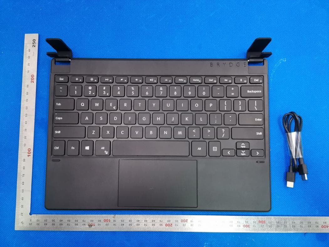
2ADRG-BRY7011
Aug 25, 2020Bluetooth Keyboard
Equipment Class
DXX - Part 15 Low Power Communication Device Transmitter
2ADRG-BRY7301
Aug 23, 2020Bluetooth keyboard
Equipment Class
DTS - Digital Transmission System
2ADRG-BRY702
Aug 23, 2020Bluetooth Keyboard
Equipment Class
DXX - Part 15 Low Power Communication Device Transmitter
2ADRG-BRYTP602N
Jul 23, 2020Bluetooth Keyboard
Equipment Class
DTS - Digital Transmission System