2ADXM5B089BTPOWER BANK SPEAKER
SHENZHEN TEKSUN TECHNOLOGY CO.,LTD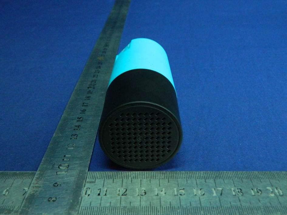
Click to zoom
Application Details
- Equipment Class
- DSS - Part 15 Spread Spectrum Transmitter
- Date of Grant
- Aug 01, 2015
- Application Purpose
- Original Equipment
- Date of Application
- Aug 01, 2015
- Equipment Note
- POWER BANK SPEAKER
- Frequency Range
- 2402.00000000 - 2480.00000000
- Country
- China
Documents & Files
Document Text
Text extracted from the exhibit documents filed with the FCC. Open a document above to read the original.
Users Manual
1 5B089BT POWER BANK SPEAKER INSTRUCTION MANUAL PLEASE READ ALL INSTRUCTIONS CAREFULLY AND RETAIN FOR FUTURE USE 2 Getting Started Remove the device from the box. Remove any packaging from the product. Please retain all packaging until you have checked and counted all the parts and the contents against the parts list. Package Contents Power Bank Speaker USB rechargeable cable Instruction Manual Key Features Charge any mobile device on‐the‐go with built‐in charger Wirelessly stream music from up to 30‐33 feet away Connects via Bluetooth to most smartphones, tablets, computers and other Bluetooth enabled devices Perfect for travel use, outdoors or anywhere you go Built‐in microphone for hands‐free‐calls USB rechargeable battery Battery Level Indicators ‐ Short press the Power ON/OFF Button to see SAFETY INSTRUCTIONS Keep the unit away from heat sources, direct sunlight, humidity, water and any other liquids. Do not operate the unit if it has been exposed to water, moisture or any other liquids to prevent against electric shock, explosion and/or injury to yourself and damage to the unit. Do not use the unit if it has been dropped or damaged in any way. Repairs to electrical equipment should only be performed by a qualified electrician. Improper repairs may place the user at serious risk. Do not use the unit with wet hands. Do not put objects into any of the openings. Keep the unit free from dust, lint etc. Do not use this unit for anything other than its intended use. Keep the unit out of reach of children. This appliance is not a toy. Do not use the handset at excessive levels as damage to hearing may occur. Batteries (battery pack or batteries installed) shall not be exposed to excessive heat place, such as sunshine, fire or the like. 3 Description of Parts Buttons Function Operation 1 Speaker Sound output 2 Charging Port (Micro USB) DC Charging Port – To charge the speaker 3 USB Charging Port Use this USB Charging Port to charge your smart phones and other mobile devices 4 Power ON/OFF Button Turn On/Off the speaker 5 Short press will return to the previous track, or long press will decrease the volume level 4 6 Short press will skip to the next track, or long press will increase the volume level 7 Play / Pause button Phone button Short press will pause or restart the music. Call Answer / Call End / Reject Call button. 8 LED Light Indicator Indicates the Charging or Bluetooth Status 9 Built‐In Mic For Hands‐Free Conversation INSTRUCTIONS FOR USE Turning ON/OFF the Speaker – Before Turning ON the device, please ensure that the unit is fully charged. Press the On/Off button to turn ON/OFF the speaker. Connect using Bluetooth Technology manually Turn On the device. You would hear a beep tone indicating that you are now in Bluetooth Pairing Mode and Blue LED Light keeps flashing. Activate the Bluetooth function on your Bluetooth Device (Mobile Phone or Tablet). Please refer to manufacturer’s instructions for instructions on enabling Bluetooth on your device. Once you have activated Bluetooth on your device, select the device “SL PB SPEAKER” from the list of available Bluetooth devices. If required, enter the password ‘0000’ to confirm to finalize pairing. (Password is required only during pairing devices for the first time) Once paired successfully, the LED light flashes slowly. Choose music from your Bluetooth® device and play music wireless through the speakers. Talking using the Bluetooth Speaker Please ensure that you are paired with the Bluetooth Speaker to use the below functions. Function Operation Button Answer Incoming Call Incoming Call Short press the ‘Phone button’ to answer an incoming call Reject incoming call Incoming Call Long press the ‘Phone button’ for 3 seconds End Call Incoming Call After your phone conversation, short press the ‘Phone button’ Volume Increase During a call Long press on the button will increase the volume Volume Decrease During a call Long press on the button will decrease the volume Redial last number Standby mode and connected to a device Short touch the ‘Phone button’ twice. 5 Listening to Music via Bluetooth Please ensure that your device (iPhone, Tablet or Other Smart Phone) is paired with the Bluetooth Speaker to stream music wirelessly. Once it is paired, play music from your device. Function Operation Button Volume Increase Playing music Long press on the button will increase the volume (Short press to skip to next track) Volume Decrease Playing music Long press on the button will decrease the volume (Short press to skip to previous track) Pause Playing music Short press on the ‘Play / Pause’ button will pause the music Play Pausing Short press on the ‘Play / Pause’ button will resume the music [Note: An indication tone will alert you when the volume is adjusted to the maximum or minimum level.) Recharging External Devices (through this speaker) Use the USB Charging port located at the back of the speaker to charge your external devices like smart phones etc. Using this saves you from having an extra charger to keep your devices powered. Charging the speaker The device has built‐in rechargeable battery. When the battery is drained out, device would turn OFF automatically. You would have to recharge the battery. Plug the included USB cable into the charging port. Plug the other end into a USB port on your computer or other devices made for USB charging. The Blue LED Light will flash indicating that the device is being charged. It takes 5 to 6 hours to fully charge the device. Once the device is fully charged, all 4 LED Lights would stay on. Specifications – Bluetooth® Version: 2.1 Wireless Distance: 30 to 33 feet Working time : Music ~4 hours, Talk ~6 hours Speaker: 3 Watts Unit size: Dia. 1.75”x4.13”(L) Unit weight: 5.2 Oz Power Input: DC 5V Built‐In Rechargeable Battery: 2600mAh Built‐in 3.7V rechargeable Li‐ion battery 6 Charging Time: 5 to 6 Hours USB Charging Port – 5V / 1A (Ma…
Text truncated - open the document above for the full version.
Cover Letter(s)
SCS-F18: Project and Product Certification Representative Authorization Letter Page 1 of 2 Rev 5.0 775 Montague Expressway Milpitas, CA 95035 Tel: 408-526-1188 Fax: 408-526-1088 Email: [email protected] Project and Product Certification Representative Authorization Letter Reason for Amendment (current / obsolete) Revision History Approved Date From To Initial Release (obsolete) 1.0 1.0 Nov-14-2006 Revised wording (obsolete) 1.0 2.0 Sept–25-2007 Updated company template (obsolete) 2.0 3.0 Jan-31-2012 Updated letter information (obsolete) 3.0 4.0 May-23-2014 Added FCC ID field (current) 4.0 5.0 Sept 16 2014 SCS-F18: Project and Product Certification Representative Authorization Letter Page 2 of 2 Rev 5.0 SHENZHEN TEKSUN TECHNOLOGY CO.,LTD 2015-07-30 To: SIEMIC, INC. 775 Montague Expressway, Milpitas, CA 95035 USA Dear Sir/Madam, Re: Product Certification Representative Authorization Letter We,SHENZHEN TEKSUN TECHNOLOGY CO.,LTD hereby authorize SIEMIC, Inc. to act as a Certification Body for certifying for the following project(s): POWER BANK SPEAKER Model Number: 5B089BT FCC ID: 2ADXM5B089BT Sincerely, Mandy Peng/PMC E-mail: [email protected] t Phone: 0755-29402650 Fax: 0755-29402650 Address 3F, bldg F7, F518 Idea Land ,Baoyuan Road,Xixiang Avenue, Bao'an District, Shenzhen, China
Cover Letter(s)
SCS-F19: Confidentiality Request Letter Page 1 of 2 Rev 4.0 775 Montague Expressway Milpitas, CA 95035 Tel: 408-526-1188 Fax: 408-526-1088 Email: [email protected] Confidentiality Request Letter Reason for Amendment (current / obsolete) Revision History Approved Date From To Initial Release (obsolete) 1.0 1.0 Nov-14-2006 Adding CFR 2.459 (obsolete) 1.0 2.0 August – 11 - 2008 Updated company template & Added text box (obsolete) 2.0 3.0 Jan-31-2012 Added IC confidentiality letter form (current) 3.0 4.0 March-26-2015 SCS-F19: Confidentiality Request Letter Page 2 of 2 Rev 4.0 SHENZHEN TEKSUN TECHNOLOGY CO.,LTD 2015-07-30 To: Federal Communications Commission Authorization and Evaluation Division 7435 Oakland Mills Road Columbia, MD Subject: Permanent Confidentiality Request for FCC ID: 2ADXM5B089BT We hereby request confidential treatment of information accompanying this application as outlined below: - Block Diagram - Schematics - Operational Description The above materials contain trade secrets and proprietary information not customarily released to the public. The public disclosure of these materials may be harmful to the applicant and provide unjustified benefits to its competitors. The applicant understands that pursuant to Section 0.457 & 0.459 of the Rules, disclosure of this application and all accompanying documentation will not be made before the date of the Grant for this application. Sincerely, Signature Mandy Peng/PMC E-mail: [email protected] Phone: 0755-29402650 Fax: 0755-29402650 Address 3F, bldg F7, F518 Idea Land ,Baoyuan Road,Xixiang Avenue, Bao'an District, Shenzhen, China
External Photos
PHOTOGRAPHS OF EUT (EXTERNAL PHOTO)
ID Label/Location Info
Label Location
Internal Photos
Antenna Module
RF Exposure Info
FCC ID: 2ADXM5B089BT Portable device According to §15.247(e)(i) and §1.1307(b)(1), systems operating under the provisions of this section shall be operated in a manner that ensures that the public is not exposed to radio frequency energy level in excess of the Commission’s guidelines. According to KDB447498 D01 General RF Exposure Guidance V05 The 1-g and 10-g SAR test exclusion thresholds for 100 MHz to 6 GHz at test separation distances ≤ 50 mm are determined by: [(max. power of channel, including tune-up tolerance, mW)/(min. test separation distance, mm)] * [√f(GHz)] ≤ 3.0 for 1-g SAR and ≤ 7.5 for 10-g extremity SAR, where f(GHz) is the RF channel transmit frequency in GHz; Power and distance are rounded to the nearest mW and mm before calculation; The result is rounded to one decimal place for comparison; The test exclusions are applicable only when the minimum test separation distance is ≤ 50 mm and for transmission frequencies between 100 MHz and 6 GHz. When the minimum test separation distance is < 5 mm, a distance of 5 mm is applied to determine SAR test exclusion. We use 5mm as separation distance to calculate. Maximum measured transmitter power: Bluetooth: Transmit Frequency (GHz) Mode Measured Power (dBm) Tune-up power (dBm) Max tune-upResult 1-g SAR power(dBm)calculation 2.402 GFSK 2.37 2±1 3 0.6185 3 2.441 GFSK 2.08 2±1 3 0.6235 3 2.48 GFSK 2.24 2±1 3 0.6284 3 2.402 π/4-DQPSK 3.00 3±1 4 0.7786 3 2.441 π/4-DQPSK 2.66 3±1 4 0.7849 3 2.48 π/4-DQPSK 2.91 3±1 4 0.7911 3 2.402 8DPSK 3.20 3±1 4 0.7786 3 2.441 8DPSK 2.83 3±1 4 0.7849 3 2.48 8DPSK 3.14 3±1 4 0.7911 3 Conclusion: For the max result : 0.7911≤ 3.0 for 1-g SAR extremity SAR, No SAR is required. Signature: Date: 2015-07-30 NAME AND TITLE (Please print or type): David Lee/Manager COMPANY (Please print or type): Shenzhen EMTEK Co.,Ltd./Building 69, Majialong Industry Zone, Nanshan District, Shenzhen,Guangdong,China
Test Report
TRF No.:FCC 15.247/A Page 1 of 66 Report No.: ES150710111E Ver.1.0 Access to the World FCC 47 CFR PART 15 SUBPART C CERTIFICATION TEST REPORT For POWER BANK SPEAKER Model No.: 5B089BT FCC ID: 2ADXM5B089BT Trademark: N/A REPORT NO.: ES150710111E ISSUE DATE: July 30, 2015 Prepared for SHENZHEN TEKSUN TECHNOLOGY CO.,LTD 3F, bldg F7, F518 Idea Land ,Baoyuan Road,Xixiang Avenue, Bao'an District, Shenzhen, China Prepared by SHENZHEN EMTEK CO., LTD. Bldg 69, Majialong Industry Zone, Nanshan District, Shenzhen, Guangdong, China TEL: 86-755-26954280 FAX: 86-755-26954282 TRF No.:FCC 15.247/A Page 2 of 66 Report No.: ES150710111E Ver.1.0 Access to the World Table of Contents 1 TEST RESULT CERTIFICATION .......................................................................................................................... 3 2 EUT TECHNICAL DESCRIPTION ........................................................................................................................ 4 3 SUMMARY OF TEST RESULT ............................................................................................................................. 6 4 TEST METHODOLOGY ........................................................................................................................................ 7 4.1 GENERAL DESCRIPTION OF APPLIED STANDARDS .......................................................................... 7 4.2 MEASUREMENT EQUIPMENT USED ..................................................................................................... 7 4.3 DESCRIPTION OF TEST MODES ............................................................................................................. 8 5 FACILITIES AND ACCREDITATIONS ................................................................................................................. 9 5.1 FACILITIES ................................................................................................................................................. 9 5.2 LABORATORY ACCREDITATIONS AND LISTINGS .............................................................................. 9 6 TEST SYSTEM UNCERTAINTY ......................................................................................................................... 10 7 SETUP OF EQUIPMENT UNDER TEST ............................................................................................................. 11 7.1 RADIO FREQUENCY TEST SETUP 1 ..................................................................................................... 11 7.2 RADIO FREQUENCY TEST SETUP 2 ..................................................................................................... 11 7.3 CONDUCTED EMISSION TEST SETUP ................................................................................................. 13 7.4 BLOCK DIAGRAM CONFIGURATION OF TEST SYSTEM ................................................................. 13 7.5 SUPPORT EQUIPMENT ........................................................................................................................... 13 8 FREQUENCY HOPPING SYSTEM REQUIREMENTS ..................................................................................... 14 8.1 STA N D A R D APPLICABLE .............................................................................................................................. 14 8.2 EUT PSEUDORANDOM FREQUENCY HOPPING SEQUENCE ........................................................................... 14 8.3 EQUAL HOPPING FREQUENCY USE .............................................................................................................. 15 8.4 FREQUENCY HOPPING SYSTEM .................................................................................................................... 15 9 TEST REQUIREMENTS ...................................................................................................................................... 16 9.1 20DB BANDWIDTH ................................................................................................................................. 16 9.2 CARRIER FREQUENCY SEPARATION .................................................................................................. 22 9.3 NUMBER OF HOPPING FREQUENCIES ............................................................................................... 28 9.4 AV E R A G E TIME OF OCCUPANCY (DWELL TIME) ............................................................................. 30 9.5 MAXIMUM PEAK CONDUCTED OUTPUT POWER ............................................................................ 33 9.6 CONDUCTED SUPRIOUS EMISSION .................................................................................................... 39 9.7 RADIATED SPURIOUS EMISSION ......................................................................................................... 46 9.8 CONDUCTED EMISSION TEST .............................................................................................................. 61 9.9 ANTENNA APPLICATION ....................................................................................................................... 66 TRF No.:FCC 15.247/A Page 3 of 66 Report No.: ES150710111E Ver.1.0 Access to the World 1 TEST RESULT CERTIFICATION Applicant: SHENZHEN TEKSUN TECHNOLOGY CO.,LTD 3F, bldg F7, F518 Idea Land ,Baoyuan Road,Xixiang Avenue, Bao'an District, Shenzhen, China Manufacturer: SHENZHEN TEKSUN TECHNOLOGY CO.,LTD 3F, bldg F7, F518 Idea Land ,Baoyuan Road,Xixiang Avenue, Bao'an District, Shenzhen, China Product Description: POWER BANK SPEAKER Model Number: 5B089BT File Number: ES150710111E Date of Test: July 10, 2015 to July 30, 2015 Measurement Procedure Used: APPLICABLE STANDARDS STANDARD TEST RESULT FCC 47 CFR Part 2, Subpart J:2014 FCC 47 CFR Part 15, Subpart C:2014 PASS The above equipment was tested by SHENZHEN EMTEK CO., LTD. The test data, data evaluation, test procedures, and equipment configuration…
Text truncated - open the document above for the full version.
Test Setup Photos
Conducted Measurement Photo Radiated Emission Test
Contact Information
Applicant
Mandy Peng(PMC)
Test Firm
EMTEK (Shenzhen) Co., Ltd.David Lee
Technical Specifications
| # | Rule Parts | Frequency Range | Power Output |
|---|---|---|---|
| 1 | 15C | 2.40 GHz - 2.48 GHz | 2.10 mW |
Other Applications from SHENZHEN TEKSUN TECHNOLOGY CO.,LTD
2ADXM5B126BT
Nov 14, 2015Wireless waterproof floating speaker
Equipment Class
DXX - Part 15 Low Power Communication Device Transmitter2ADXM5B110BT
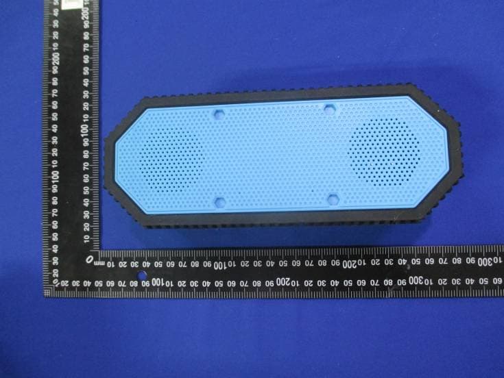
Sep 29, 2015Bluetooth Speaker with LED Lantern
Equipment Class
DSS - Part 15 Spread Spectrum Transmitter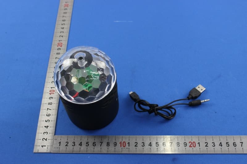
2ADXM56808BT
Aug 24, 2015Bluetooth Speaker
Equipment Class
DSS - Part 15 Spread Spectrum Transmitter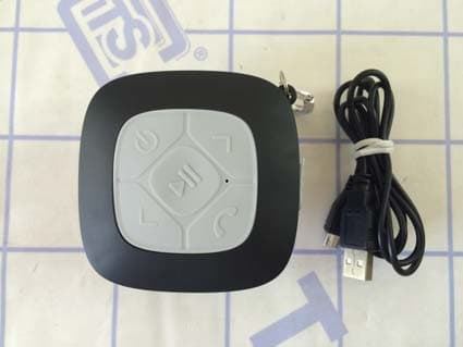
2ADXM521050BT
Jul 05, 2015Bluetooth Shower Speaker
Equipment Class
DXX - Part 15 Low Power Communication Device Transmitter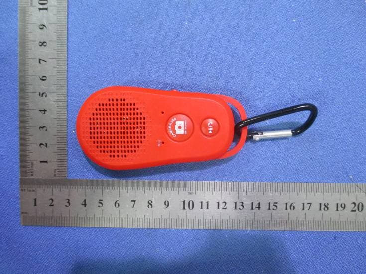
2ADXM56902BT
Jun 13, 2015Bluetooth Speaker
Equipment Class
DXX - Part 15 Low Power Communication Device Transmitter