2ADZF-S0001S0001
i1 SensorTech, Inc. D.B.A Athlete Intelligence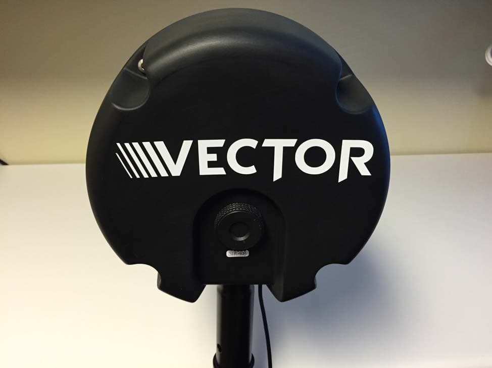
Click to zoom
Application Details
- Equipment Class
- DSS - Part 15 Spread Spectrum Transmitter
- Date of Grant
- Feb 22, 2015
- Application Purpose
- Original Equipment
- Date of Application
- Feb 22, 2015
- Equipment Note
- S0001
- Frequency Range
- 902.40000000 - 927.20000000
- Country
- United States
Documents & Files
Document Text
Text extracted from the exhibit documents filed with the FCC. Open a document above to read the original.
Users Manual
IMPACT INTELLIGENCE SYSTEM SET UP INSTRUCTIONS Lenovo Yoga 2 Pro (includes i1 Biometrics Event Software) S0001 Side Line Receiver (SLR) Tripod SLR stand 1. Remove and set up tripod raising mast to approximately 6 feet high. 2. Place SLR onto tripod through hole in base of SLR. 3. Secure SLR to tripod mast by tightening thumb screw. 4. Place tripod with attached SLR at midfield such that the domed end points directly at the field of play. 5. Unwrap attached USB cord from SLR and insert into Yoga laptop. 6. Power on Yoga laptop. 7. Launch i1 Biometrics Event Software by clicking on desktop icon. Per FCC 15.19(a)(3) and (a)(4) This device complies with part 15 of the FCC Rules. Operation is subject to the following two conditions: (1) This device may not cause harmful interference, and (2) this device must accept any interference received, including interference that may cause undesired operation. Per FCC 15.21, Changes or modifications made to this equipment not expressly approved by the party responsible for compliance could void the user's authority to operate the equipment Per RSS‐Gen, Section 8.4, this device complies with Industry Canada license‐exempt RSS standard(s). Operation is subject to the following two conditions: (1) this device may not cause interference, and (2) this device must accept any interference, including interference that may cause undesired operation of the device. Par RSS‐Gen, la section 8.4, cet appareil est conforme avec Industrie Canada exempts de licence standard RSS (s). Son fonctionnement est soumis aux deux conditions suivantes: (1) ce dispositif ne doit pas causer d'interférences et (2) cet appareil doit accepter toute interférence, y compris les interférences qui peuvent causer un mauvais fonctionnement de l'appareil. Note: This equipment has been tested and found to comply with the limits for a Class B digital device, pursuant to part 15 of the FCC Rules. These limits are designed to provide reasonable protection against harmful interference in a residential installation. This equipment generates, uses and can radiate radio frequency energy and, if not installed and used in accordance with the instructions, may cause harmful interference to radio communications. However, there is no guarantee that interference will not occur in a particular installation. If this equipment does cause harmful interference to radio or television reception, which can be determined by turning the equipment off and on, the user is encouraged to try to correct the interference by one or more of the following measures: Reorient or relocate the receiving antenna. Increase the separation between the equipment and receiver. Connect the equipment into an outlet on a circuit different from that to which the receiver is connected. Consult the dealer or an experienced radio/TV technician for help. This Class B digital apparatus complies with Canadian ICES‐003. Cet appareil numerique de la classe B est conforme a la norme NMB‐003 du Canada.
Cover Letter(s)
FCC Compliance Opinion 2015-1-14 I1BM0002 Information about the Applicant Grantee (Company Name) i1 SensorTech, Inc. FCC Contact Person Tom Nuxoll Address 12020 113th Avenue NE Suite 210 City, State, Zip Kirkland, WA 98034 Job Number I1BM0002 Model S0001 FCC ID 2ADZF-S0001 Agent Approval Type Original Equipment Class DSS Part 15, Spread Spectrum Transmitter Rule Part 15.247 Overview The i1 SensorTech S0001 is a side line receiver (SLR) base station which receives real‐time head impact data transmitted from individual Vector mouth guards via a ISM 900MHz radio link. The SLR operates while connected to a side line laptop connected via USB. The SLR contains a single radio PCB and a permanently attached Dual‐Dipole FPC antenna embedded within the device internally cabled to the radio PCB. The SLR contains a 900MHz ISM band frequency‐hopping spread spectrum (FHSS) radio which consists of a RF‐Transceiver (CC1101) + LNA/PA Front End (CC1190) all controlled by a low‐ power microcontroller (MSP430). Recommendation All items have been resolved and completed to my satisfaction; therefore I recommend this application for approval. Signature Dave Tolman, TCB Committee 2/16/2015
Operational Description
Antenna Info: Permanently attached Custom dual‐polarized dipole antenna printed on flex with soldered SMA coaxial feed cable. Connectorized end of coaxial feed cable connects internally to main radio board. The antenna design meets the requirements of FCC 15.203 to ensure that no other antenna can be used with the device by being enclosed in the antenna housing and inaccessible to the end user. Peak Gain: +2.4dBi
RF Exposure Info
This report must not be used to claim product certification, approval, or endorsement by NVLAP, NIST, or any agency of the federal government of the United States of America. This Report may only be duplicated in its entirety i1 Biometrics, Inc. Sideline Receiver FCC 2.1091:2014 Report # I1BM0002.3 NVLAP Lab Code: 200629-0 CERTIFICATE OF EVALUATION 2014-12-10 Product compliance is the responsibility of the client; therefore, the tests and equipment modes of operation represented in this report were agreed upon by the client, prior to testing. The results of this test pertain only to the sample(s) tested. The specific description is noted in each of the individual sections of the test report supporting this certificate of test. Last Date of Test: December 31, 2014 i1 Biometrics, Inc. Model: Sideline Receiver Radio Equipment Testing Standards Specification Method FCC 2.1091:2014 OET Bulletin 65, Supplement C Ed 01-01 Results Method Clause Test Description Applied Results Comments 7.1 Maximum Permissible Exposure Yes Pass Deviations From Test Standards None Approved By: Don Facteau, IT Manager Report No. I1BM0002.32/9 REVISION HISTORY REV 2014.10.14 Revision Number Description Date Page Number 00 None Report No. I1BM0002.33/9 ACCREDITATIONS AND AUTHORIZATIONS REV 2014.10.08 United States FCC - Designated by the FCC as a Telecommunications Certification Body (TCB). Certification chambers, Open Area Test Sites, and conducted measurement facilities are listed with the FCC. A2LA - Accredited by A2LA to ISO / IEC Guide 65 as a product certifier. This allows Northwest EMC to certify transmitters to FCC and IC specifications. NVLAP - Each laboratory is accredited by NVLAP to ISO 17025 Canada IC - Recognized by Industry Canada as a Certification Body (CB). Certification chambers and Open Area Test Sites are filed with IC. European Union European Commission – Validated by the European Commission as a Conformity Assessment Body (CAB) under the EMC directive and as a Notified Body under the R&TTE Directive. Australia/New Zealand ACMA - Recognized by ACMA as a CAB for the acceptance of test data. Korea MSIP / RRA - Recognized by KCC’s RRA as a CAB for the acceptance of test data. Japan VCCI - Associate Member of the VCCI. Conducted and radiated measurement facilities are registered. Taiwan BSMI – Recognized by BSMI as a CAB for the acceptance of test data. NCC - Recognized by NCC as a CAB for the acceptance of test data. Singapore IDA – Recognized by IDA as a CAB for the acceptance of test data. Israel MOC – Recognized by MOC as a CAB for the acceptance of test data. Hong Kong OFTA – Recognized by OFTA as a CAB for the acceptance of test data. Vietnam MIC – Recognized by MIC as a CAB for the acceptance of test data. SCOPE For details on the Scopes of our Accreditations, please visit: http://www.nwemc.com/accreditations/ Report No. I1BM0002.34/9 FACILITIES REV 2014.10.08 California Labs OC01-13 41 Tesla Irvine, CA 92618 (949) 861-8918 Minnesota Labs MN01-08, MN10 9349 W Broadway Ave. Brooklyn Park, MN 55445 (612)-638-5136 New York Labs NY01-04 4939 Jordan Rd. Elbridge, NY 13060 (315) 685-0796 Oregon Labs EV01-12 22975 NW Evergreen Pkwy Hillsboro, OR 97124 (503) 844-4066 Texas Labs TX01-09 3801 E Plano Pkwy Plano, TX 75074 (469) 304-5255 Washington Labs NC01-05 19201 120 th Ave NE Bothell, WA 9801 (425)984-6600 NVLAP NVLAP Lab Code: 200676-0 NVLAP Lab Code: 200881-0 NVLAP Lab Code: 200761-0 NVLAP Lab Code: 200630-0 NVLAP Lab Code:201049-0 NVLAP Lab Code: 200629-0 Industry Canada 2834B-1, 2834B-3 2834E-1 N/A 2834D-1, 2834D-2 2834G-1 2834F-1 BSMI SL2-IN-E-1154R SL2-IN-E-1152R N/A SL2-IN-E-1017 In Process SL2-IN-E-1153R VCCI A- 0029 A- 0109 N/A A- 0108 A- 0201 A- 0110 Report No. I1BM0002.35/9 PRODUCT DESCRIPTION 2014-12-10 Client and Equipment Under Test (EUT) Information Company Name: i1 Biometrics, Inc. Address: 12020 113th Avenue NE Suite 210 City, State, Zip: Kirkland, WA 98034 Test Requested By: David Brown Model: Sideline Receiver Evaluation Date: December 31, 2014 Information Provided by the Party Requesting the Test Functional Description of the EUT: Sideline Receiver Testing Objective: To demonstrate compliance with FCC requirements for RF exposure for 2.1091 mobile devices Report No. I1BM0002.36/9 MAXIMUM PERMISSIBLE EXPOSURE (MPE) WTD.2014.12.17 OVERVIEW Human exposure to RF emissions from mobile devices (47 CFR §2.1091) may be evaluated based on the MPE limits adopted by the FCC for electric and magnetic field strength and/or power density, as appropriate, since exposures are assumed to occur at distances of 20 cm or more from persons. ANSI C95.1-1992 specifies a minimum separation distance of 20 cm for performing reliable field measurements to determine adherence to MPE limits. If the minimum separation distance between a transmitter and nearby persons is more than 20 cm under normal operating conditions, compliance with MPE limits may be determined at such distance from the transmitter. When applicable, operation instructions and prominent warning labels may be used to alert the exposed persons to maintain a specified distance from the transmitter or to limit their exposure durations and usage conditions to ensure compliance. If the use of warning labels on a transmitter is not effective or desirable, the alternative of performing SAR evaluation with the device at its closest range to persons under normal operating conditions may be used. The field strength and power density limits adopted by the FCC are based on whole-body averaged exposure and the assumption of RF field levels relate most accurately to estimating whole-body averaged SAR. This means some local values of exposures exceeding the stated field strength and power density limits may not necessarily imply non-compliance if the spatial average of spatially averaged RF fields over the exposed portions of a person’s body does not exceed the limits. COMPLIANCE WITH 2.1091 “Mobile devices that operate in the Cellular Radiotelephone Servi…
Text truncated - open the document above for the full version.
Test Report
This report must not be used to claim product certification, approval, or endorsement by NVLAP, NIST, or any agency of the federal government of the United States of America. This Report may only be duplicated in its entirety i1 Biometrics, Inc. Sideline Receiver FCC 15.207:2014 FCC 15.247:2014 Report # I1BM0002.1 NVLAP Lab Code: 200629-0 CERTIFICATE OF TEST 2014-12-10 Product compliance is the responsibility of the client; therefore, the tests and equipment modes of operation represented in this report were agreed upon by the client, prior to testing. The results of this test pertain only to the sample(s) tested. The specific description is noted in each of the individual sections of the test report supporting this certificate of test. Last Date of Test: December 23, 2014 i1 Biometrics, Inc. Model: Sideline Receiver Radio Equipment Testing Standards Specification Method FCC 15.207: 2014 ANSI C63.10:2009 FCC 15.247:2014 ANSI C63.10:2009 Results Method Clause Test Description Applied Results Comments 6.2 AC Powerline Conducted Emissions Yes Pass 6.5, 6.6 Spurious Radiated Emissions Yes Pass 6.7 Spurious Conducted Emissions Yes Pass 6.9.1 Occupied Bandwidth Yes Pass 6.10.1 Output Power Yes Pass 7.7.2 Channel Separation Yes Pass 7.7.3 Number of Hopping Channels Yes Pass 7.7.4 Dwell Time Yes Pass 7.5 Duty Cycle Yes Pass 7.7.9 Band Edge Compliance Yes Pass 7.7.9 Band Edge Compliance - Hopping Mode Yes Pass Deviations From Test Standards None Approved By: Rod Munro, Operations Manager Report No. I1BM0002.12/59 REVISION HISTORY REV 2014.10.14 Revision Number Description Date Page Number 00 None Report No. I1BM0002.13/59 ACCREDITATIONS AND AUTHORIZATIONS REV 2014.10.08 United States FCC - Designated by the FCC as a Telecommunications Certification Body (TCB). Certification chambers, Open Area Test Sites, and conducted measurement facilities are listed with the FCC. A2LA - Accredited by A2LA to ISO / IEC Guide 65 as a product certifier. This allows Northwest EMC to certify transmitters to FCC and IC specifications. NVLAP - Each laboratory is accredited by NVLAP to ISO 17025 Canada IC - Recognized by Industry Canada as a Certification Body (CB). Certification chambers and Open Area Test Sites are filed with IC. European Union European Commission – Validated by the European Commission as a Conformity Assessment Body (CAB) under the EMC directive and as a Notified Body under the R&TTE Directive. Australia/New Zealand ACMA - Recognized by ACMA as a CAB for the acceptance of test data. Korea MSIP / RRA - Recognized by KCC’s RRA as a CAB for the acceptance of test data. Japan VCCI - Associate Member of the VCCI. Conducted and radiated measurement facilities are registered. Taiwan BSMI – Recognized by BSMI as a CAB for the acceptance of test data. NCC - Recognized by NCC as a CAB for the acceptance of test data. Singapore IDA – Recognized by IDA as a CAB for the acceptance of test data. Israel MOC – Recognized by MOC as a CAB for the acceptance of test data. Hong Kong OFTA – Recognized by OFTA as a CAB for the acceptance of test data. Vietnam MIC – Recognized by MIC as a CAB for the acceptance of test data. SCOPE For details on the Scopes of our Accreditations, please visit: http://www.nwemc.com/accreditations/ Report No. I1BM0002.14/59 MEASUREMENT UNCERTAINTY TMU.2014.12.03 Measurement Uncertainty When a measurement is made, the result will be different from the true or theoretically correct value. The difference is the result of tolerances in the measurement system that cannot be completely eliminated. To the extent that technology allows us, it has been our aim to minimize this error. Measurement uncertainty is a statistical expression of measurement error qualified by a probability distribution. A measurement uncertainty estimation has been performed for each test per our internal quality document WP 342. The estimation is used to compare the measured result with its "true" or theoretically correct value. The expanded measurement uncertainty (K=2) for each test is on each data sheet. Our measurement data meets or exceeds the measurement uncertainty requirements of the applicable specification; therefore, the test data can be compared directly to the specification limit to determine compliance. The calculations for estimating measurement uncertainty are based upon ETSI TR 100 028 (or CISPR 16-4-2 as applicable), and are available upon request. The following table represents the Measurement Uncertainty (MU) budgets for each of the tests that may be contained in this report. Test + MU - MU Frequency Accuracy (Hz) 0.0007% -0.0007% Amplitude Accuracy (dB) 1.2 dB -1.2 dB Conducted Power (dB) 0.3 dB -0.3 dB Radiated Power via Substitution (dB) 0.7 dB -0.7 dB Temperature (degrees C) 0.7°C -0.7°C Humidity (% RH) 2.5% RH -2.5% RH Voltage (AC) 1.0% -1.0% Voltage (DC) 0.7% -0.7% Field Strength (dB) 4.5 dB -4.5 dB AC Powerline Conducted Emissions (dB) 2.9 dB -2.9 dB Report No. I1BM0002.15/59 FACILITIES REV 2014.10.08 California Labs OC01-13 41 Tesla Irvine, CA 92618 (949) 861-8918 Minnesota Labs MN01-08, MN10 9349 W Broadway Ave. Brooklyn Park, MN 55445 (612)-638-5136 New York Labs NY01-04 4939 Jordan Rd. Elbridge, NY 13060 (315) 685-0796 Oregon Labs EV01-12 22975 NW Evergreen Pkwy Hillsboro, OR 97124 (503) 844-4066 Texas Labs TX01-09 3801 E Plano Pkwy Plano, TX 75074 (469) 304-5255 Washington Labs NC01-05 19201 120 th Ave NE Bothell, WA 9801 (425)984-6600 NVLAP NVLAP Lab Code: 200676-0 NVLAP Lab Code: 200881-0 NVLAP Lab Code: 200761-0 NVLAP Lab Code: 200630-0 NVLAP Lab Code:201049-0 NVLAP Lab Code: 200629-0 Industry Canada 2834B-1, 2834B-3 2834E-1 N/A 2834D-1, 2834D-2 2834G-1 2834F-1 BSMI SL2-IN-E-1154R SL2-IN-E-1152R N/A SL2-IN-E-1017 In Process SL2-IN-E-1153R VCCI A-0029 A-0109 N/A A-0108 A-0201 A-0110 Report No. I1BM0002.16/59 PRODUCT DESCRIPTION 2014-12-10 Client and Equipment Under Test (EUT) Information Company Name: i1 Biometrics, Inc. Address: 12020 113th Avenue NE Suite 210 City, State, Zip: Kirkland, …
Text truncated - open the document above for the full version.
Test Setup Photos
AC POWERLINE CONDUCTED EMISSIONS WTD.2014.10.14 PSA-ESCI 2014.09.10, EmiR5 2014.11.10 photo SRE (1).JPG SRE (2).JPG SPURIOUS RADIATED EMISSIONS PSA-ESCI 2014.09.10 Report No. I1BM0002.12/13 photo SRE (3).JPG SRE (4).JPG SPURIOUS RADIATED EMISSIONS PSA-ESCI 2014.09.10 Report No. I1BM0002.13/13 photo SRE (5).JPG SRE (6).JPG SPURIOUS RADIATED EMISSIONS PSA-ESCI 2014.09.10 Report No. I1BM0002.14/13 SPURIOUS CONDUCTED EMISSIONS XMit 2014.02.07 NORTHWEST SPURIOUS CONDUCTED EMISSIONS NweTx 2014.11.06 EMC Direct Connect (1).JPG Direct Connect (2).JPG SPURIOUS CONDUCTED EMISSIONS Report No. I1BM0002.15/13 OCCUPIED BANDWIDTH XMit 2014.02.07 NORTHWEST OCCUPIED BANDWIDTH NweTx 2014.11.06 EMC Direct Connect (1).JPG Direct Connect (2).JPG OCCUPIED BANDWIDTH Report No. I1BM0002.16/13 OUTPUT POWER XMit 2014.02.07 NORTHWEST OUTPUT POWER NweTx 2014.11.06 EMC Direct Connect (1).JPG Direct Connect (2).JPG OUTPUT POWER Report No. I1BM0002.17/13 CHANNEL SEPARATION XMit 2014.02.07 NORTHWEST CHANNEL SEPARATION NweTx 2014.11.06 EMC Direct Connect (1).JPG Direct Connect (2).JPG CHANNEL SEPARATION Report No. I1BM0002.18/13 NUMBER OF HOPPING CHANNELS XMit 2014.02.07 NORTHWEST NUMBER OF HOPPING CHANNELS NweTx 2014.11.06 EMC Direct Connect (1).JPG Direct Connect (2).JPG NUMBER OF HOPPING CHANNELS Report No. I1BM0002.19/13 DWELL TIME XMit 2014.02.07 NORTHWEST DWELL TIME NweTx 2014.11.06 EMC Direct Connect (1).JPG Direct Connect (2).JPG DWELL TIME Report No. I1BM0002.110/13 DUTY CYCLE XMit 2014.02.07 NORTHWEST DUTY CYCLE NweTx 2014.11.06 EMC Direct Connect (1).JPG Direct Connect (2).JPG DUTY CYCLE Report No. I1BM0002.111/13 BAND EDGE COMPLIANCE XMit 2014.02.07 NORTHWEST BAND EDGE COMPLIANCE NweTx 2014.11.06 EMC Direct Connect (1).JPG Direct Connect (2).JPG BAND EDGE COMPLIANCE Report No. I1BM0002.112/13 BAND EDGE COMPLIANCE -HOPPING MODE XMit 2014.02.07 NORTHWEST BAND EDGE COMPLIANCE -HOPPING MODE NweTx 2014.11.06 EMC Direct Connect (1).JPG Direct Connect (2).JPG BAND EDGE COMPLIANCE - HOPPING MODE Report No. I1BM0002.113/13
Contact Information
Applicant
Andrew Golden(VP Operations)
Test Firm
Northwest EMC, Inc.Greg Kiemel
Technical Specifications
| # | Rule Parts | Frequency Range | Power Output |
|---|---|---|---|
| 1 | 15C | 902.4 MHz - 927.2 MHz | 443.00 mW |
Other Applications from i1 SensorTech, Inc. D.B.A Athlete Intelligence
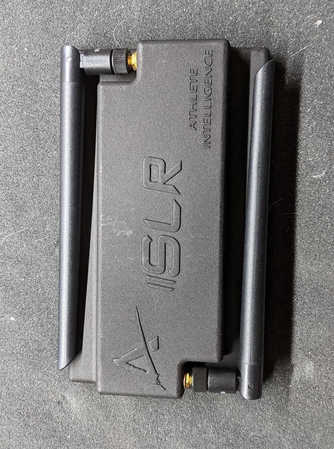
2ADZF-S0002
Jul 17, 2022915 - 923 MHz Transceiver
Equipment Class
DTS - Digital Transmission System
2ADZF-D0002
Jun 14, 2022915 - 923 MHz Transceiver
Equipment Class
DTS - Digital Transmission System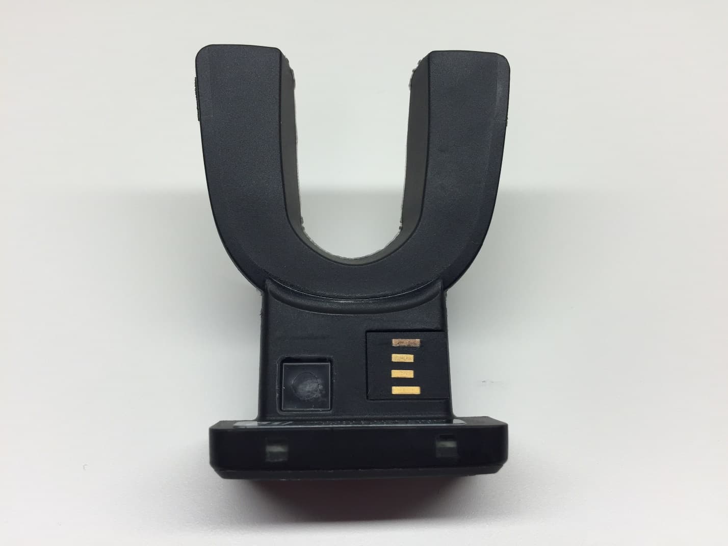
2ADZF-D0001
Feb 22, 2015D0001
Equipment Class
DSS - Part 15 Spread Spectrum Transmitter