2ADZF-S0002915 - 923 MHz Transceiver
i1 SensorTech, Inc. D.B.A Athlete Intelligence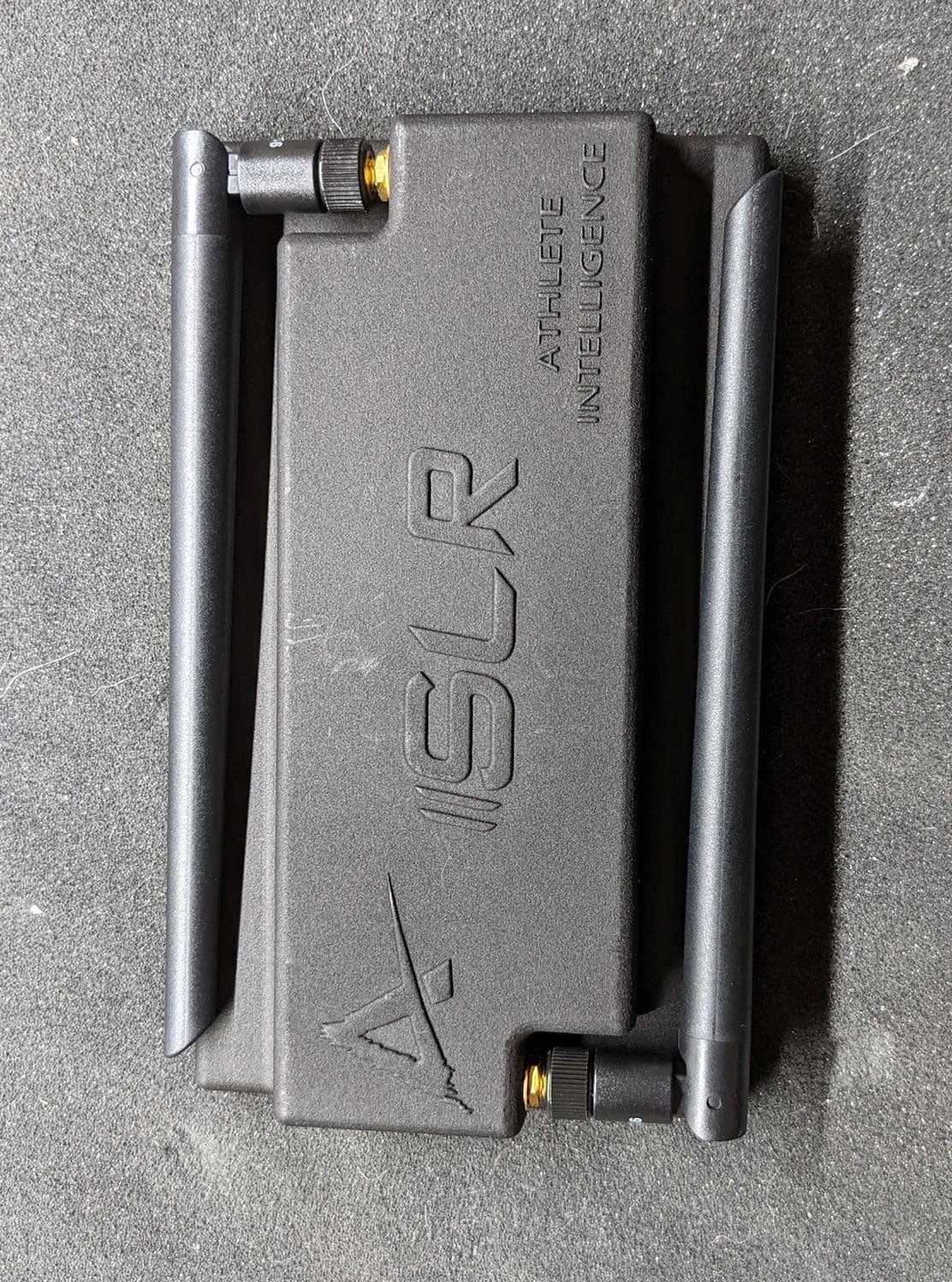
Click to zoom
Application Details
- Equipment Class
- DTS - Digital Transmission System
- Date of Grant
- Jul 17, 2022
- Application Purpose
- Original Equipment
- Date of Application
- Jul 17, 2022
- Equipment Note
- 915 - 923 MHz Transceiver
- Frequency Range
- 915.00000000 - 923.00000000
- Country
- United States
Documents & Files
Document Text
Text extracted from the exhibit documents filed with the FCC. Open a document above to read the original.
Users Manual
Team User Manual 1 | P a g e [email protected] | (425)372-7811 IMPROVE PERFORMANCE | IMPROVE SAFETY About Athlete Intelligence Athlete Intelligence is a sports data analytics company specializing in head-impact monitoring and performance tracking solutions. Using the Athlete Intelligence Platform with our innovative wearables, Coaching and sideline professionals can gain access to data they have never had access to previously to: Improve Athlete Technique Manage Head-Impact Exposure Reduce the Risk of Injury Stop Guessing, Start Monitoring Since 2015, Athlete Intelligence has been on the field with some of sports top teams and most prestigious research institutions globally to provide on-field head-impact monitoring. At Athlete Intelligence, we strive each day to elevate athletic performance while helping to keep athletes safe. With a main goal of building better athletes, we accomplish this by providing Coachable Moments allowing staff to improve technique, manage head-impact exposure, and reduce the risk of injury. Using integrated technology, athletic staff, has an objective view of what happens during games and practices to better analyze and adjust player behavior. It is recommended to read the user manual thoroughly prior to use. If you need any assistance at all, please contact our Customer Support Team directly at (425)372-7811 or by e-mailing [email protected] Product Warning: No mouthguard sensor or helmet sensor can prevent, diagnose, or identify concussions. If concussion symptoms become apparent in an athlete, please remove the athlete from play. Athlete Intelligence analytics platform is designed to empower decision making of sideline professionals, not replace it. FCC Notice: This device complies with Part 15 of the FCC Rules. Operation is subject to the following two conditions: (1) this device may not cause harmful interference, and (2) this device must accept any interference received, including interference that may cause undesired operation. To ensure compliance with FCC RF exposure for the SLR+, a minimum 20cm separation distance from users and bystanders should be maintained when both transmitters are transmitting simultaneously. Changes or modifications not expressly approved by the manufacturer could void the user’s ability to operate the equipment. 2 | P a g e [email protected] | (425)372-7811 IMPROVE PERFORMANCE | IMPROVE SAFETY Table of Contents About Athlete Intelligence Page 1 Product Warning Page 1 FCC Notice Page 1 System Components Page 4 Daily Best Practices Page 5 Product Specifications Page 5 Initial Set-Up Completed System Tasks by Athlete Intelligence Page 6 Administrator Set-Up Tasks 1. Complete Admin Account Set-Up Page 6 2. Confirm Access to Web Platform Page 7 3. Create Your Team(s) Page 7-9 4. Pre-Set Practice and Game Sessions Page 9 5. Create Additional Team User Profiles Page 10-11 6. Verify Team Roster Page 12-13 7. Set-Up Automated Reports Page 14 8. Install Sideline Manager Computer Application Page 15 9. Download AI Team Mobile App Page 15 Testing System Connectivity Page 16 Placing Clips in Helmets Page 17-25 Daily On-Field Operations Page 26 About the Web Platform Page 27 Athlete Intelligence Web Platform Icons Page 28 Administrative Page Page 29 Team Settings Page 30 Player Comparison Reports Page 31 Roster Management Page 32 Edit Player Page 33 Dashboard Reports Page 34 Device Status Page 35 3 | P a g e [email protected] | (425)372-7811 IMPROVE PERFORMANCE | IMPROVE SAFETY Table of Contents (continued) Gameday Live Feed Page 36 About the AI TEAM Mobile App Page 37 Mobile App Home Screen Icons Page 38 Player Status Screen Page 39 Today’s Impacts Page 40 Frequently Asked Questions Page 41 4 | P a g e [email protected] | (425)372-7811 IMPROVE PERFORMANCE | IMPROVE SAFETY System Components 1. CUE+ Helmet Sensor 2. CUE+ Sensor Mounting Clip 3. Sideline Receiver (SLR+) 4. Bulk Charging Board 5. Jersey Stickers 6. Helmet Velcro 7. Clip Velcro 8. iOS or Android Mobile Phone (Not Included) AI Web Platform The AI Web Platform is our secure cloud platform used for account, team, and player management. All player impact data and historic analytics are also stored in the Web Platform, which is accessible from any computer. Use the Web Platform during Live Mode or to view reports and trends post practice or game at any time. AI TEAM Mobile Application The AI Team mobile application is your live stream of impacts during use and where you receive notifications. 5 | P a g e [email protected] | (425)372-7811 IMPROVE PERFORMANCE | IMPROVE SAFETY Daily Best Practices To ensure the highest level of data collection, we suggest the following best practices are followed for each practice and game day when the CUE+ helmet sensors. It is recommended to use the system in Live Mode. CUE+ Product Specifications Weight 0.6 oz Impact Memory Storage 2,000 Impacts Transmission Range 180 Yards (540 Ft) Live Data Streaming (915 Mhz) Charging Method 30 Unit Bulk Charging Board Battery Life 24 hours in Active Mode Impact Monitoring Location, Quantity, Severity Mobile Accessibility iOS, Android. Apple Watch Impact Notifications Uninterrupted, Real-Time From the field, confirm Wi-Fi connection and connectivity to the CUE+. Make sure SLM, SLR, and devices remain connected when on the field. If status is green, your system is set-up and ready to begin a session. When the practice or game begins, select, start session from the Home screen in the mobile application (if sessions are not pre- scheduled). Impacts will display when in session. Once the practice or game has ended, select, end session (if sessions have not been pre-scheduled). This will close the window for displayable impacts. Reports and analytics can now be reviewed in the Web Platform. Make sure your CUE+ are in the charging board and charging when not in use. Plug in your SLR into your windows computer and use the Device Status p…
Text truncated - open the document above for the full version.
Cover Letter(s)
i1 SensorTech, Inc. 7 33 7 th Ave. Suite 215 Kirkland, WA 980 33 Request for Confidentiality Date: 6/21/2021 Subject: Confidentiality Request for: FCC ID: 2ADZF-S0002 Pursuant to FCC 47 CFR 0.457(d) and 0.459, the applicant requests that a part of the subject FCC application be held confidential. Type of Confidentiality Requested D Short Term IZl Permanent D Short Term D Sho1i Term D Permanent * 1 D Short Term IZl Permanent □Short Term D Permanent □Short Term D Permanent D Short Term IZl Permanent D Short Term D Sho1i Term D Permanent * 3 Exhibit Block Diagrams External Photos Internal Photos Operation Description/Theory of Operation Parts List & Placement/BOM Tune-Up Procedure Schematics Test Setup Photos User's Manual i 1 SensorTech, Inc. has spent substantial effort in developing this product and it is one of the first of its kind in industry. Having the subject information easily available to "competition" would negate the advantage they have achieved by developing this product. Not protecting the details of the design will result in financial hardship. Permanent Confidentiality: The applicant requests the exhibits listed above as permanently confidential be permanently withheld from public review due to materials that contain trade secrets and proprietary information not customarily released to the public. Short-Term Confidentiality: The applicant requests the exhibits selected above as short term confidential be withheld from public view for a period of Q 2 days from the date of the Grant of Equipment Authorization and prior to marketing. This is to avoid premature release of sensitive information prior to marketing or release of the product to the public. Applicant is also aware that they are responsible to notify ACB in the event information regarding the product or the product is made available to the public before the requested period has expired. ACB will then release the documents listed above for public disclosure pursuant to FCC Public Notice DA 04-1705. Sincerely, By: Andrew Golden (Print name) 1 -The asterisked items (*) require further information to be provided to ACB before permanent confidentiality will be extended to these exhibits. Please refer to FCC KDB 726920 and the specific Document link for D01 found at: https://apps.fcc.gov/oetdi'kdb/forms/FTSSearchResultPage.cfm?switch = P&id=4173 I and review section II, 3) regarding specific information that must accompany these requests. 2 -Please refer to http://acbcert.com/documents/misc-docs/Merno-Short-Term-Vs-Standard-Confidentiality.pdf for complete details. - Must be signed by applicant contact given for applicant on the FCC site, or by the authorized agent if an appropriate authorized agent letter has been provided. Letters should be placed on appropriate letterhead.
External Photos
SLR+ Top External Photo External whip antenna P/N: TI.92.2113 External whip antenna P/N: TI.92.2113 SLR+ Bottom External Photo
ID Label/Location Info
FCC ID Label ID Label Location on Bottom of SLR+
Internal Photos
SLR+ Internal Photos Custom Whip Antenna with RP-SMA Connector RP-S MA Coax Cable U.FL to RP-SMA Coax to external Custom whip antenna U.FL to RP-SMA Coax to external Custom whip antenna Ferrite P/N: 10461178181 Ferrite P/N: 10461178181 Silicon Labs SoC with RF transmitter Silicon Labs SoC with RF transmitter SLR+ Top Internal Photo SLR+ Bottom Internal Photo
RF Exposure Info
Rhein Tech Laboratories, Inc. Client: i1 SensorTech, Inc. 360 Herndon Parkway Model #: SLR+ Suite 1400 Standards: 15.247 Herndon, VA 20170 FCC ID: 2ADZF-S0002 http://www.rheintech.com Report #: 2021077 Page 34 of 41 Appendix A: RF Exposure FCC Part 1.1307, 1.1310, 2.1091, 2.1093 MPE Co-location Calculations The maximum permissible RF exposure for an uncontrolled environment is specified in FCC 1.1310 table 1B. From OET 65, S = EIRP / 4πR 2 where: S = Power density (mw/cm 2 ) EIRP = Equivalent Isotropic Radiated Power R = 20 cm separation distance Power Density Conducted power is 0.087 W Maximum antenna gain for this frequency range of operation is 1.2 dBi (1.32 numeric) S = 0.023 mW/cm 2 = at 20 cm separation Co-location - Summary of MPE Transmitter Frequency (MHz) MPE Result (mW/cm 2 ) FCC Limit (mW/cm 2 ) Ratio TX1 915 - 923 0.023 0.6 0.04 TX2 915 - 923 0.023 0.6 0.04 Sum of Ratios 0.08 Sum of ratios = 0.08 < 1, therefore compliant. Thus, the EUT meets the uncontrolled exposure limit at 20 cm when both transmitters are transmitting simultaneously.
Test Report
Engineering Solutions & Electromagnetic Compatibility Services 360 Herndon Pkwy | Suite 1400 | Herndon | Virginia 20170 Phone: 703.689.0368 | Fax: 703.689.2056 | www.rheintech.com FCC Part 15.247 Certification Report Test Lab: Rhein Tech Laboratories, Inc. Phone: 703-689-0368 360 Herndon Parkway Fax: 703-689-2056 Suite 1400 www.rheintech.com Herndon, VA 20170 Applicant: i1 SensorTech, Inc. Phone: 425-372-7811 733 7th Avenue Suite 215 Kirkland, WA 98033 USA FCC ID 2ADZF-S0002 Test Report Date April 25, 2022 Platform N/A RTL Work Order Number 2021077 Model SLR+ RTL Quote Number QRTL21-077A American National Standard Institute ANSI C63.10-2013: American National Standard of Procedures for Compliance Testing of Unlicensed Wireless Devices FCC Classification DTS – Digital Transmission System FCC Rule Part(s) Part 15.247: Operation within the bands 902-928 MHz, 2400-2483.5 MHz and 5725-5850 MHz (10-01-2020) Frequency Range (MHz) Output Power (W)* Frequency Tolerance Emission Designator 915 – 923 0.087 N/A 1M66F1D *Power is conducted peak I, the undersigned, hereby declare that the equipment tested and referenced in this report conforms to the identified standard(s) as described in this test report. No modifications were made to the equipment during testing in order to achieve compliance with these standards. Furthermore, there was no deviation from, additions to, or exclusions from, the applicable parts of FCC Part 2, FCC Part 15, and ANSI C63.10. Signature: Date: April 25 , 2022 Typed/Printed Name: Desmond A. Fraser Position: President This report may not be reproduced, except in full, without the written approval of Rhein Tech Laboratories, Inc. and i1 SensorTech, Inc. The test results relate only to the item(s) tested. Replaces R2.1. These tests are accredited and meet the requirements of ISO/IEC 17025 as verified by ANAB. Refer to certificate and scope of accreditation AT-1445. Rhein Tech Laboratories, Inc. Client: i1 SensorTech, Inc. 360 Herndon Parkway Model #: SLR+ Suite 1400 Standards: 15.247 Herndon, VA 20170 FCC ID: 2ADZF-S0002 http://www.rheintech.com Report #: 2021077 Page 2 of 41 Table of Contents 1 General Information .................................................................................................................................. 5 1.1 Scope ................................................................................................................................................... 5 1.2 Description of EUT ............................................................................................................................... 5 1.3 Test Facility .......................................................................................................................................... 5 1.4 Related Submittal(s)/Grant(s) .............................................................................................................. 5 1.5 Modifications ........................................................................................................................................ 5 2 Test Information ........................................................................................................................................ 6 2.1 Description of Test Modes ................................................................................................................... 6 2.2 Exercising the EUT .............................................................................................................................. 6 2.3 Test Result Summary ........................................................................................................................... 6 2.4 Test System Details ............................................................................................................................. 6 2.5 Configuration of Tested System ........................................................................................................... 7 3 Maximum Conducted Output Power – FCC 15.247(b)(3) ........................................................................ 8 3.1 Power Output Test Procedure.............................................................................................................. 8 3.2 Power Output Test Data ....................................................................................................................... 8 4 Band Edge Compliance of RF Conducted Emissions – FCC 15.247(d) ................................................ 11 4.1 Band Edge Test Procedure ................................................................................................................ 11 4.2 Test Results ....................................................................................................................................... 12 5 Antenna Conducted Spurious Emissions – FCC 15.247(d) ................................................................... 14 5.1 Antenna Conducted Spurious Emissions Test Procedures ............................................................... 14 5.2 Antenna Conducted Spurious Emissions Test Results ..................................................................... 15 6 6 dB Bandwidth – FCC 15.247(a)(2) ...................................................................................................... 19 6.1 6 dB Bandwidth Test Procedure ........................................................................................................ 19 6.2 Bandwidth Test Results ..................................................................................................................... 19 7 Power Spectral Density – FCC 15.247(e) .............................................................................................. 22 7.1 Power Spectral Density Test Procedure ............................................................................................ 22 7.2 Power Spectral Density Test Data .............................................................…
Text truncated - open the document above for the full version.
Test Setup Photos
Rhein Tech Laboratories, Inc. Client: i1 SensorTech, Inc. 360 Herndon Parkway Model #: SLR+ Suite 1400 Standards: 15.247 Herndon, VA 20170 FCC ID: 2ADZF-S0002 http://www.rheintech.com Report #: 2021077 Page 40 of 48 Appendix I: Test Photographs Photograph 1: Radiated Emissions (Below 1 GHz) Front View Rhein Tech Laboratories, Inc. Client: i1 SensorTech, Inc. 360 Herndon Parkway Model #: SLR+ Suite 1400 Standards: 15.247 Herndon, VA 20170 FCC ID: 2ADZF-S0002 http://www.rheintech.com Report #: 2021077 Page 41 of 48 Photograph 2: Radiated Emissions (Below 1 GHz) Back View Rhein Tech Laboratories, Inc. Client: i1 SensorTech, Inc. 360 Herndon Parkway Model #: SLR+ Suite 1400 Standards: 15.247 Herndon, VA 20170 FCC ID: 2ADZF-S0002 http://www.rheintech.com Report #: 2021077 Page 42 of 48 Photograph 3: Radiated Emissions (Above 1 GHz) Front View Rhein Tech Laboratories, Inc. Client: i1 SensorTech, Inc. 360 Herndon Parkway Model #: SLR+ Suite 1400 Standards: 15.247 Herndon, VA 20170 FCC ID: 2ADZF-S0002 http://www.rheintech.com Report #: 2021077 Page 43 of 48 Photograph 4: Radiated Emissions (Above 1 GHz) Back View Rhein Tech Laboratories, Inc. Client: i1 SensorTech, Inc. 360 Herndon Parkway Model #: SLR+ Suite 1400 Standards: 15.247 Herndon, VA 20170 FCC ID: 2ADZF-S0002 http://www.rheintech.com Report #: 2021077 Page 44 of 48 Photograph 5: Conducted Antenna Port Rhein Tech Laboratories, Inc. Client: i1 SensorTech, Inc. 360 Herndon Parkway Model #: SLR+ Suite 1400 Standards: 15.247 Herndon, VA 20170 FCC ID: 2ADZF-S0002 http://www.rheintech.com Report #: 2021077 Page 45 of 48 Photograph 6: AC Conducted Emissions (Front View) Rhein Tech Laboratories, Inc. Client: i1 SensorTech, Inc. 360 Herndon Parkway Model #: SLR+ Suite 1400 Standards: 15.247 Herndon, VA 20170 FCC ID: 2ADZF-S0002 http://www.rheintech.com Report #: 2021077 Page 46 of 48 Photograph 7: AC Conducted Emissions (Back View)
Contact Information
Applicant
Andrew Golden(VP Operations)
Test Firm
Rhein Tech Laboratories, Inc.Richard McMurray
Technical Specifications
| # | Rule Parts | Frequency Range | Power Output |
|---|---|---|---|
| 1 | 15C | 915 MHz - 923 MHz | 174.00 mW |
Other Applications from i1 SensorTech, Inc. D.B.A Athlete Intelligence

2ADZF-D0002
Jun 14, 2022915 - 923 MHz Transceiver
Equipment Class
DTS - Digital Transmission System
2ADZF-S0001
Feb 22, 2015S0001
Equipment Class
DSS - Part 15 Spread Spectrum Transmitter
2ADZF-D0001
Feb 22, 2015D0001
Equipment Class
DSS - Part 15 Spread Spectrum Transmitter