2AEBDIP01IP-CAM
Kenxen Electronic (SZ) Limited.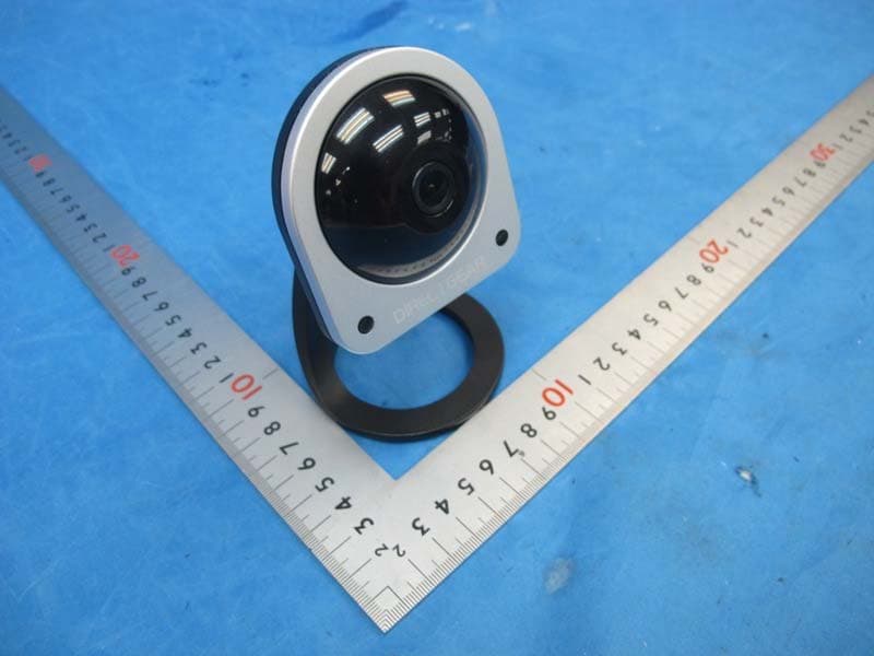
Click to zoom
Application Details
- Equipment Class
- DTS - Digital Transmission System
- Date of Grant
- Apr 18, 2015
- Application Purpose
- Original Equipment
- Date of Application
- Apr 18, 2015
- Equipment Note
- IP-CAM
- Frequency Range
- 2412.00000000 - 2462.00000000
- Country
- China
Documents & Files
Document Text
Text extracted from the exhibit documents filed with the FCC. Open a document above to read the original.
Users Manual
Cloud Camera User Manual 1. Introduction IP01 Cloud Camera is designed for middle, small enterprise & normal family use and it can monitor your environment in 24 hours every day. night time. It supports Wireless connection and it is convenient to setup & operate. • 802.11n Wireless Standard; • Motion & sound detection; • Wireless connection and no need for network wire connection; • High quality level 720P CMOS sensor; • Send snapshot or video to cloud server; environment. Dimensions124 X 80 X 35mm Weight208 g AudioLinear input/output two-way voice intercom Audio compression PCM or ADPCM Video compressionH.264 Working frequency50Hz / 60Hz Video Format720p / 512kbps , WVGA / 256kbps, WQVGA / 128kbps Exposure balanceAutomatic White balanceAutomatic Infrared modeAutomatic Night vision8 infrared lights, infrared irradiation distance: 3-4meters Supported protocolTCP/IP Wireless standardWIFI(IEEE802.11b/g/n) Support IP addresses Dynamic IP are supported Operating temperature 0° ~ 40°C Operating humidity10% ~ 85% (non-condensing) Storage temperature -10°C ~ 60° Storage humidity10% ~ 85%(non-condensing) Operation systemMicrosoft Windows 2000/XP, Vista, Windows7, Windows8,Mac OS, Linux Alarm detectionMotion detection support Noise Detection 3. Introduction on appearance Front Back USB port Microphone Wi-Fi indicator IR light Camera IR Sensor Speaker Reset 4. Ways to assemble wall mount Right Base Wall mount Wrong 5. Before setup a) Connect your mobile to your Wi-Fi router b) Connect the USB cable to the IP camera and the USB power adaptor, plug in the power adaptor into the power socket c) Wait for around 30 second for device startup, there is a flash green light at the right on the IP camera Output: 5V 1AInput: 5V 1A 6. Start up and register a) Click the “DirectGear” on the screen b) You will see the “DIRECTGEAR” logo shown c) The first time you start, the Sign up screen will show d) Type in an e-mail address and password into the relate field. Retype the password for double confirm e) Click the “Sign up” button to register f) You will received an e-mail for the registration, click the link on the e-mail to confirm a) The first time login, it prompt for e-mail address and password b) Click “Log in” after finish type in a) If forgot the password, select the lower right corner “Forgot password” at the “Log in” b) Type in the e-mail address c) Click “Send” and system will send an e-mail to your mailbox to reset your password a) After login, the first screen will show which said “Your account is lonely. It needs a camera. Add on by tapping below.” b) Click the “Add camera” c) The add camera welcome screen will show d) You need your mobile connect to the same Wi-Fi network. Then click “OK” e) Follow the instruction on the screen, then click “Next” f ) Press the “Reset” button at the back of the IP camera for at least two seconds until you hear a “beep” sound. Then click “Next” on the screen i) It will scan the QR code on the mobile screen. Usually take 2~5 seconds. After you hear the “beep beep” sound, you can click the “Yes, I heard it” button. j) It will automatic configure the IP camera, it need takes around 20 to 30 seconds. k) After finished, it will show two fields which you can change the device name and time zone. Click “Let’s go” after finish modify. Now the camera is ready. g) It will prompt to select the Wi-Fi network and input the password. Press “Next” when finished. h) Read the instruction on the screen. It asks you hold the mobile in front of the camera between 10cm~20cm after click the “OK”. DIRECTGEAR 7. The login 8. Forgot password 9. Add camera 11. Camera settings (IP camera needs to connected state) a) Preferences of the camera i. Camera name: users can change the name or choose a default name ii. Location: choose the Greenwich mean time b) Camera i. Camera: enable or disable the camera ii. Camera off at: Scheduling the camera on/off time c) Cloud recording (need enable the cloud service) i. Recording: enable or disable the cloud recording ii. Recording off at: Scheduling the recording on/off time d) Services i. Closeli plan: Your cloud service plan status. If expired, you can select the plan here and it will forward to the online billing website e) General settings i. Notification settings Motion detection: Enable/disable motion detection Motion area settings: Drag to set an area in the grid to detect motion To exit the app, click the mobile “Back” button and it will ask you “Are you sure you want to exit?” Select “Exit” to quit. Warning: Changes or modifications to this unit not expressly approved by the party responsible for compliance could void the user’s authority to operate the equipment. NOTE: This equipment has been tested and found to comply with the limits for a Class B digital device, pursuant to Part 15 of the FCC Rules. These limits are designed to provide reasonable protection against harmful interference in a residential installation. This equipment generates, uses and can radiate radio frequency energy and, if not installed and used in accordance with the instructions, may cause harmful interference to radio communications. However, there is no guarantee that interference will not occur in a particular installation. If this equipment does cause harmful interference to radio or television reception, which can be determined by turning the equipment off and on, the user is encouraged to try to correct the interference by one or more of the following measures: Reorient or relocate the receiving antenna. Increase the separation between the equipment and receiver. Connect the equipment into an outlet on a circuit different from that to which the receiver is connected. Consult the dealer or an experienced radio/TV technician for help. For MPE (Fixed or Mobile Device) “FCC RF Radiation Exposure Statement Caution: To maintain compliance with the FCC’s RF exposure guidelines, place the product at least 20cm from nearby persons.” 10. My Cameras (main screen) 12. Account a) A…
Text truncated - open the document above for the full version.
Cover Letter(s)
5 16/Mar/2015 To whom it may concern, Letter of Agency I, an officer of Kenxen Electronic (SZ) Limited. do hereby authorize Intertek Testing Services (Mr. Tommy Leung / Shawn Xing) to act on our behalf in front of the Federal Communications Commission with respect to all matters relating to certification of equipment under FCC Part 15 of the FCC Rules until further notice. I further certify that no party (as defined in §1.2002(b) of CFR 47, 2007) to this application, including myself, is subject to a denial of federal benefits, that includes FCC benefits, pursuant to Section 5301 of the Anti- Drug Abuse Act of 1988, 21 U.S.C., 862. Regards, ____ Jason Lim General Manager
Cover Letter(s)
2AEBDIP01 Kenxen Electronic (SZ) Limited W hom it may concern, Re: Request for confidentiality Applicant: FCC ID: To Permanent Confidentiality Request is hereby submitted by to withhold permanently from public review certain portions of the application for equipment certification for the referenced FCC identifiers. This request for confidentiality is made pursuant to 47 CFR 0.457(d) and 0.459 of the FCC Rules. In particular, the following sections of the application are to be kept permanently confidential: Schematics Detailed Block diagrams Detailed Operational/Functional Description Short-term Confidentiality Request is hereby submitted by to withhold from public review for a period of 45 days from the date of the Grant of Equipment Authorization and prior to marketing, certain portions of the application for equipment certification for the referenced FCC identifiers. This request for confidentiality is made pursuant to 47 CFR 0.457(d) and 0.459 of the FCC Rules. In particular, the following sections of the application are to be kept confidential for a period of 45 days from the date of Authorization: Test setup photos External photos Internal photos User manual Rationale for request for confidentiality: has invested considerable time and materials in research and development to produce the referenced product. [Permanent confidentiality: Disclosure of the permanently confidential portions of this application to competitors would not only give them significant competitive advantages in developing similar products, but would also disclose successful implementation of unpublished, leading edge technology developed by us.][Short term confidentiality: Disclosure of the short-term confidential portions of this application during the period of importation and/or distribution would reveal key aspects of proprietary technology to competitors and diminish the value of our investment in research and development.] If you have questions or need further information, please contact the undersigned. Sincerely, Kenxen Electronic (SZ) Limited Kenxen Electronic (SZ) Limited Kenxen Electronic (SZ) Limited Jason Lim General Manager Kenxen Electronic (SZ) Limited
External Photos
External Photos
ID Label/Location Info
Model No. : IP01 USB 5V 1A F MAC Address:2059A0C00068 Made in China CC ID : 2AEBDIP01
Internal Photos
Internal Photos
RF Exposure Info
INTERTEK TESTING SERVICES FCC ID: 2AEBDIP01 RF Exposure report The Equipment Under Test (EUT) is a IP-Cam with WiFi function operating at 2412-2462MHz for 802.11b/g/n-HT20, 11 channels with 5MHz channel spacing and 2422-2452MHz for 802.11n-HT40, 9 channels with 5MHz channel spacing. The EUT was powered by AC120V/60Hz. For more detailed features description, please refer to the user’s manual. Modulation Type: BPSK, QPSK, 16QAM, 64QAM for OFDM. CCK, DQPSK, DBPSK for DSSS. Antenna Type: Integral antenna Antenna Gain: 2dBi The nominal conducted output power specified: 19dBm (Tolerance: +/-5dB) The maximum conducted output power for the EUT is 23.4 dBm in the frequency 2.462GHz 802.11g mode which is within the production variation. The minimum conducted output power for the EUT is 17.8 dBm in the frequency 2.437GHz 802.11b mode which is within the production variation. According to FCC Part 2.1091, this unlicensed transmitting devices is categorically excluded from routine environmental evaluation for RF exposure prior to equipment authorization or use. For Maximum Permissible Exposure (MPE) evaluation of the product, the maximum power density at 20 cm from this transmitter shall be less than the General Population / Uncontrolled MPE limit in FCC Part 1.1310. The maximum EIRP= 19+5+2=26dBm=398.1mW The source-based time averaged maximum radiated power = 398.1 x Duty Cycle = 398.1mW From above data, the exposed power density at a distance (R) of 20cm from the center of radiation of the antenna can be calculated according to OET Bulletin 65 as follow: = PG/4πR^2 = EIRP/4πR^2 = 398.1/ 4πR^2 = 0.08 mW/cm^2 INTERTEK TESTING SERVICES FCC ID: 2AEBDIP01 The MPE limit is 1.0 mWcm-2 for general population and uncontrolled exposure in the WiFi frequency range according to FCC Part 1.1310. As the measured power density at 20cm from the transmitter is lower than the MPE limit, the compliance to the MPE limit can be ensured by indicating the minimum 20cm separation between the transmitter's radiating structure and body of the user or nearby persons. Transmitter Duty Cycle Calculation The EUT transmit continuously during the test, the duty cycle is 1. The following RF exposure statement or similar sentence is proposed to be included in the user manual: “FCC RF Radiation Exposure Statement Caution: This Transmitter must be installed to provide a separation distance of at least 20 cm from all persons.”
Test Report
The test results reported in this test report shall refer only to the sample actually tested and shall not refer or be deemed to refer to bulk from which such a sample may be said to have been obtained. This report is for the exclusive use of Intertek's Client and is provided pursuant to the agreement between Intertek and its Client. Intertek's responsibility and liability are limited to the terms and conditions of the agreement. Intertek assumes no liability to any party, other than to the Client in accordance with the agreement, for any loss, expense or damage occasioned by the use of this report. Only the Client is authorized to copy or distribute this report. Any use of the Intertek name or one of its marks for the sale or advertisement of the tested material, product or service must first be approved in writing by Intertek. The observations and test results referenced from this report are relevant only to the sample tested. This report by itself does not imply that the material, product, or service is or has ever been under an Intertek certification program. For Terms And Conditions of the services, it can be provided upon request. The evaluation data of the report will be kept for 3 years from the date of issuance. TRF no.: FCC 15C_Tx_b Intertek Testing Services Shenzhen Ltd. Kejiyuan Branch 6F, D Block, Huahan Building, Langshan Road, Nanshan District, Shenzhen, P. R. China Tel: (86 755) 8601 6288 Fax: (86 755) 8601 6751 Website: www.china.intertek-etlsemko.com Kenxen Electronic (SZ) Limited. Application For Certification FCC ID: 2AEBDIP01 IP-Cam Model: IP01 2.4GHz WiFi Transceiver Report No.: 141222019SZN-001 We hereby certify that the sample of the above item is considered to comply with the requirements of FCC Part 15, Subpart C for Intentional Radiator, mention 47 CFR [10-1-13] Prepared and Checked by: Approved by: Sign on file Sunny Zhou Engineer Andy Yan Senior Project Engineer Date: April 09, 2015 INTERTEK TESTING SERVICE TRF no.: FCC 15C_TX_b FCC ID: 2AEBDIP01 Report No.: 141222019SZN-001 i LIST OF EXHIBITS INTRODUCTION EXHIBIT 1: Summary of Tests EXHIBIT 2: General Description EXHIBIT 3: System Test Configuration EXHIBIT 4: Measurement Results EXHIBIT 5: Equipment Photographs EXHIBIT 6: Product Labeling EXHIBIT 7: Technical Specifications EXHIBIT 8: Instruction Manual EXHIBIT 9: Confidentiality Request EXHIBIT 10: Miscellaneous Information EXHIBIT 11: Test Equipment List INTERTEK TESTING SERVICES TRF no.: FCC 15C_TX_b FCC ID: 2AEBDIP01 Report No.: 141222019SZN-001 ii MEASUREMENT/TECHNICAL REPORT IP-Cam Model: IP01 FCC ID: 2AEBDIP01 This report concerns (check one) Original Grant X Class II Change Equipment Type: DTS - Part 15 Digital Transmission Systems (WiFi transmitter portion) Deferred grant requested per 47 CFR 0.457(d)(1)(ii)? Yes No X If yes, defer until : date Company Name agrees to notify the Commission by: date of the intended date of announcement of the product so that the grant can be issued on that date. Transition Rules Request per 15.37? Yes No X If no, assumed Part 15, Subpart C for intentional radiator - the new 47 CFR [10-01-13] Edition] provision. Report prepared by: Sunny Zhou Intertek Testing Services Shenzhen Ltd. Kejiyuan Branch 6F, Block D, Huahan Building, Langshan Road, Nanshan District, Shenzhen, P. R. China Phone: (86 755) 8614 0695 Fax: (86 755) 8614 6751 INTERTEK TESTING SERVICES TRF no.: FCC 15C_TX_b FCC ID: 2AEBDIP01 Report No.: 141222019SZN-001 iii Table of Contents 1.0 Summary of Test results ............................................................................................................................. 2 2.0 General Description ...................................................................................................................................... 4 2.1 Product Description ..................................................................................................................................... 4 2.2 Related Submittal(s) Grants ....................................................................................................................... 5 2.3 Test Methodology ........................................................................................................................................ 5 2.4 Test Facility .................................................................................................................................................. 5 3.0 System Test Configuration ......................................................................................................................... 7 3.1 Justification .................................................................................................................................................. 7 3.2 EUT Exercising Software ............................................................................................................................ 7 3.3 Special Accessories .................................................................................................................................... 7 3.4 Measurement Uncertainty .......................................................................................................................... 8 3.5 Equipment Modification .............................................................................................................................. 8 3.6 Support Equipment List and Description ................................................................................................ 8 4.0 Measurement Results ................................................................................................................................. 10 4.1 Maximum Conducted Output Power at Antenna Terminals ..................................................................... 10 4.2 Minimum 6 dB RF Bandwidth .................................................................................................................. 12 4.3 Maximum Power Density Reading ..…
Text truncated - open the document above for the full version.
Test Setup Photos
Radiated Emission
Test Setup Photos
Conducted Emission
Contact Information
Applicant
Jason Lim(General Manager)
Technical Contact
Intertek Testing Services Shenzhen Ltd. Kejiyuan BShawn Xing
[email protected](86-755) 8614 0603
6F, D Block, Huahan Building, Langshan Road · Shenzhen · China
Non-Technical Contact
Intertek Testing Services Shenzhen Ltd. Kejiyuan BShawn Xing
[email protected](86-755) 8614 0603
Test Firm
Intertek Testing Services Shenzhen Ltd.Shawn Xing
Technical Specifications
| # | Rule Parts | Frequency Range | Power Output |
|---|---|---|---|
| 1 | 15C | 2.41 GHz - 2.46 GHz | 218.80 mW |
Other Applications from Kenxen Electronic (SZ) Limited.
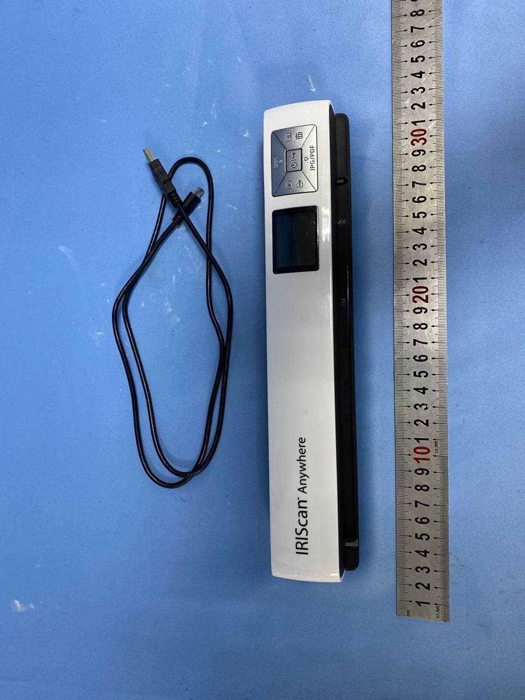
2AEBD-ANYWHERE
May 09, 2021Scanner
Equipment Class
DTS - Digital Transmission System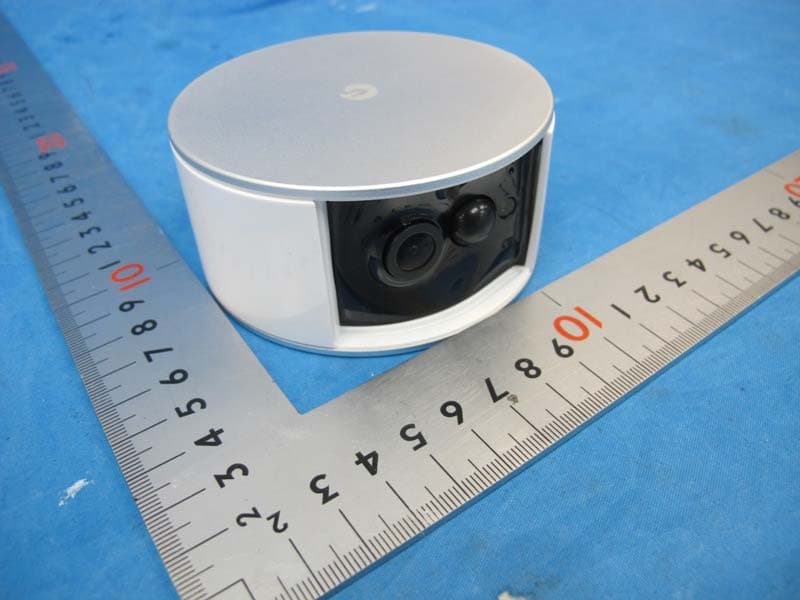
2AEBDBU4001
Apr 14, 2015IP-CAM
Equipment Class
DTS - Digital Transmission System