2AEBHAR2101B1Remote Control Transmitter
Guangde Ledup Enterprise Inc.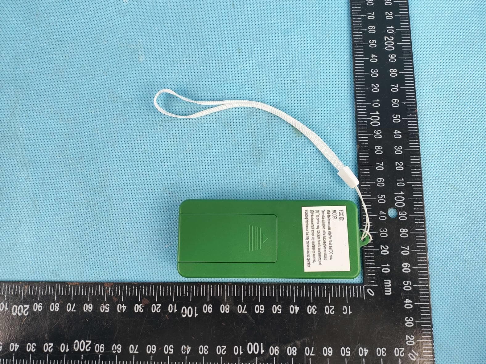
Click to zoom
Application Details
- Equipment Class
- DXX - Part 15 Low Power Communication Device Transmitter
- Date of Grant
- Mar 10, 2021
- Application Purpose
- Original Equipment
- Date of Application
- Mar 10, 2021
- Equipment Note
- Remote Control Transmitter
- Frequency Range
- 2402.00000000 - 2402.00000000
- Country
- China
Documents & Files
Document Text
Text extracted from the exhibit documents filed with the FCC. Open a document above to read the original.
Users Manual
LED21 Model No. 10AR-2101B1 Made in China Printed in China This is not a toy, for decorative use only. DISTRIBUTED BY HOME DEPOT U.S.A., INC. 2455 PACES FERRY RD., N.W. Atlanta, GA 30339 All rights reserved. Simply spread the branch tips upward and outward. THE TREE IS JUST NOT FULL ENOUGH? A LIGHT SET OR AREA IS OUT? Simply check the connections on your Quick Set® pole. MISPLACED YOUR REMOTE CONTROL? Operate the color & function by phone or tablet! DOWNLOAD THE APP! UNDECIDED? WHITE OR MULTI LIGHTS? This tree provides you with both options! ? 1. Gently remove the plug from its electrical outlet, and carefully bind the cord which contains the on/off push button foot pedal and plug. 2. Beginning with the tree’s top section; lift each section straight up from the section below, and continue working downward. NOTE: You may have to slightly wiggle each section as you lift each section upward. 3. To remove the bottom and final section; loosen the eyebolt by turning in a counter-clockwise direction and lift section “A” from the support collar of the tree stand. 4. Gently fold the branches of each section upward, towards the center, utilizing the fabric strapping provided and position in the storage container. NOTE: With the exception of the tree’s “top” section; by holding each section upside down; the branches will collapse downward, due to the hinging, aiding in the packing of each section into the storage container. 5. Unthread the eyebolt from the tree’s stand and fold together; placing in the storage container. 6. It is recommended to always store the tree in a cool, dry location protected from excessive exposure to heat or sunlight. NOTE: Store your remote control in a SAFE & DRY location and remove the batteries from remote control before storage. NOTE: ALTHOUGH THE LED LIGHT STRINGS ON THE TREE ARE RATED FOR INDOOR OR OUTDOOR USE; THE COMBINATION OF THE TREE WITH THE LED LIGHTS IS FOR INDOOR USE ONLY. DISASSEMBLY & STORAGE This product was pre-tested before shipment and date coded. In keeping with the National Electric Code, this product is intended for seasonal (90 days max.) installation and use. For problems or questions on this product call our customer service toll-free at 1-877-527-0313. TROUBLESHOOTING 1. If the tree does not illuminate press the on/off button on your remote control. If failure to light persists, the battery may need to be replaced. Insert 2 x AAA batteries. NOTE: The tree’s 10 function lighting capability is controlled by the use of the remote control provided, by phone or tablet - by down loading the App. NOTE: By reducing the distance from your tree; you may achieve better remote control and App reception. If the tree fails to light due to a damaged or defective remote control; please resort to App operation until a new remote control can be provided through our customer service center. 2. If failure to light persists, press the on/off push button foot pedal; as it may be in the “Off” mode. 3. If the top of the tree or another individual lettered section does not illuminate, remove each section and then reinsert as instructed, to ensure the electrical connection is made. NOTE: The tree’s top is designed specifically for a secure and firm connection point. Downward force will be needed to ensure that the electrical connection occurs. NOTE: A SPECIALTY NON-REPLACEABLE LED HAS BEEN APPLIED TO YOUR PRE-LIT TREE; IN THE CASE THAT A INDIVIDUAL LED BULB BURNS OUT, THE REMAINING LED BULBS WILL CONTINUE TO STAY LIT. Fig 7 • HOME USE • Remote Control Operation: • Press the and buttons at the same time. - The tree will flash MULTI color twice to activate. Light Show Fig 9 COLOR CHANGING Steady WW Twinkle WW Steady MLT Slow Fade WW Slow Fade MLT Slow Color Variable Slow FadeSlow FlipFast Flip Light Show Light Show ACTIVATE YOUR REMOTE CONTROL! Press the and buttons at the same time. The tree will flash MULTI color twice to activate the “HOME USE” operation. You are now all set! COLOR CHANGING Steady WW Twinkle WW Steady MLT Slow Fade WW Slow Fade MLT Slow Color Variable Slow FadeSlow FlipFast Flip Light Show TIMER FEATURE: • Press the “Timer” button; the trees lights will flash WARM WHITE 3 times – Indicating that the 6 hour “On” / 18 hour “Off” timer has now been activated. • Note: The tree’s lights will automatically resume back to the “On” position – 24 hours from when it was initially activated. • Press the “Timer” button again, the trees lights will flash MULTI 3 times – Indicating that the timer feature has now been deactivated. • Note: The trees On/Off operation is now controlled by either the manual operation of the remote control, foot-pedal control or by the App! REMOTE CONTROL OPERATION Your Pre-Shaped & Pre-lit LED Christmas Tree’s 10 Function capability is controlled by the use of the remote control provided, (Fig 7) by phone or tablet - by down loading the App! IMPORTANT: “HOME MODE” Activation of your Remote Control. • Press the and at the same time. • The Tree will flash MULTI color twice to activate. • This double flashing of the MULTI color allows you to now operate the remote control manually (Fig 9). NOTE: Once set on “Home Mode”; If the tree is powered off by the use of the push button foot pedal, remote control , by unplugging it from the electrical outlet or by App; when powered back on, the tree will automatically default to the last color & function selected. • Please Note: If you again press these two buttons simultaneously; (whereas the tree would flash MULTI just once), the tree would now be in “Store Mode” – Causing the tree to automatically default to the “Light Show” function (after remaining in idle for just 3 minutes) – Cycling through ALL of the trees 10 lighting function combinations. Light Show Fig 8 Simply press a desired lighting function button - Per the 10 individual lighting functions available. • Light Show • Steady Warm White • Steady Multi • Twinkle Warm White • Slow Fade Warm White • Slow Fade Multi • Slow Color Variable • Fas…
Text truncated - open the document above for the full version.
Attestation Statements
Guangde Ledup Enterprise, Inc. Jingtang Road, Guangde Economic Development Zone, Guangde, Anhui, China Tel: 0563-6988761 Fax: 0563-6767137 Model Difference Statement 10NAR-2101B1 10AR-2101B1 The models 10AR-2010B1 and 10NAR-2010B1 are identical to each other except for the model name and function position of the keys. <SIGNATURE> (Lianfeng Ma) (Manager)
Cover Letter(s)
Guangde Ledup Enterprise, Inc. Jingtang Road, Guangde Economic Tel: 0563-6988761 Fax : 0 5 6 3 - 61 61 131 Development Zone, Guangde, Anhui, China POWER OF ATTORNEY 2A27/02/24 Federal Communications Commission Authorization and Evafuation Division 7435 Oakland Mills Road Colrmbia, MD 21046 To Whom It May Concern: We, the undersrgned, hereby authorize ITL Co., Ltd. (MR. pauler LI/ Manager) on our behalf, to apply to the F'ederaf Communicatlons CommissLon on our equipment. Any and all acts carried out by ITL Co., Ltd. (MR. pauler LI, Manager) on our behalf shalf have the same effect as acts of our own. This authorization expires on 202L/AB/24. This is to advise that we are in fuIl compllance with the Anti-Drug Abuse Act. we, (Guangde Ledup Enterprise, rnc.), are not subject to a denial of federal benefits pursuant to Section 5301 of the Anti-Drug Act of 1988, 21 USC853a, and no party to the application is subject to a denial of federal benefits pursuant to that section. ci h^^v^'t., (Guangde Ledup <S IGNATURE> (Lianfeng Ma) (Manager ) Enterprise,
Cover Letter(s)
Cuangde Ledup Enterprise, Inc. Jingtang Road, Guangde Economic Development Zone, Guangde, Federal Communications Commission 7435 Oakland Mills Road Columbia, MD 21046 Centlemen: This letter is to comply with Sectlons 0.457 and confidentlal material. Guangde Ledup Enterprise, following documents regarding thls submission for be kept confidential. Type of Confidentiality Requested Exhibit Block Diagrams External Photos Intemal Photos Operation Description/Theory of Operation Parts List & Placement/BOM Tune-Up Procedure Schematics Test Setup Photos User's Manual Short Term Short Term Short Term Short Term Short Term Short Term Short Term Short Term Short Term I Permanent Permanent*l Permanent Permanent Permanent Permanent Permanent* The above material contains trade secrets or technical data, which would customarily be guarded from competitors. We do not want these documents to be accessible to the general public. Pursuant to sections 0.457 and 0.459 of CFR 47 and to avoid premature release of sensitive information prior to marketing or release of the product to the public, the applicant requests the following documents contained in this certification application be temporarily withheld from public disclosure for an initial period of 180 days. Sincerely,
External Photos
Page 1 of 5 External PHOTO: Model: 10NAR-2010B1 Page 2 of 5 Page 3 of 5 Page 4 of 5 Page 5 of 5
ID Label/Location Info
Label location
Internal Photos
Page 1 of 2 Internal PHOTO: Model: 10NAR-2010B1 Antenna Page 2 of 2
RF Exposure Info
RF Exposure Requirements Product Description: Remote Model No.: 10NAR-2010B1 FCC ID: 2AEBHAR2101B1 IC: 20239-AR2101B1 According to the KDB-4474498 D01, RSS-102 and FCC 1.1310, the following RF exposure evaluation shall to demonstrate RF exposure compliance. F= Frequency in MHz Friis Formula Friis transmission formula: Pd=PG/4πR 2 Where Pd = power density in mW/cm2 Pout = output power to antenna in mW G = gain of antenna in linear scale Pi = 3.1416 R = distance between observation point and center of the radiator in cm Pd id the limit of MPE, 1 mW/cm2. If we know the maximum gain of the antenna and the total power input to the antenna, through the calculation, we will know the distance r where the MPE limit is reached. If we know the maximum Gain of the antenna and the total power input to the antenna, through the calculation, we will know the MPE value at distance 20cm. The software provided by Manufacturer enabled the EUT to transmit and receive data at lowest, middle and highest channel individually. Test Results Max Conducted Peak Output Power: 3.06 dbm Limit: 1.31 x 10 -2 f 0.6834 W (where f is in MHz, f=2402MHz) ≈2.676W Antenna Gain: 1dbi (Gain of antenna in linear scale: 1.26dbi) Frequency (MHz) Max Conducted Peak Output Power (dBm) e.i.r.p (dBm) Output Power to Antenna (mW) Power Density at R = 20 cm (mW/ cm 2 ) Limit (W) Result 2402 3.06 4.06 2.55 0.0006 2.676 Pass
Test Report
ITL Page 1 of 26 Report No.: D210303003 TEST REPORT Applicant: Guangde Ledup Enterprise, Inc. Address of Applicant: Jingtang Road, Guangde Economic Development Zone, Guangde, Anhui, China Manufacturer: Guangde Ledup Enterprise, Inc. Address of Manufacturer: Jingtang Road, Guangde Economic Development Zone, Guangde, Anhui, China Product name: Remote Model: 10AR-2010B1, 10NAR-2010B1 Rating(s): DC 3V battery Trademark: LEDUP Standards: 47 CFR PART 15 Subpart C: section 15.249 FCC ID: 2AEBHAR2101B1 Data of Receipt: 2021-02-24 Date of Test: 2021-02-24~2021-03-03 Date of Issue: 2021-03-04 Test Result Pass* * In the configuration tested, the test item complied with the standards specified above. Authorized for issue by: Test by: Reviewed by: Mar.04, 2021 Eleven Liang Mar.04, 2021 P Pauler Li Project Engineer Project Engineer Date Name/Position Signature Date Name/Position Signature ITL Page 2 of 26 Report No.: D210303003 Possible test case verdicts: test case does not apply to the test object .. : N/A test object does meet the requirement ........ : P (Pass) test object does not meet the requirement .. : F (Fail) Testing Laboratory information: Testing Laboratory Name .......... : ITL Co., LTD Address : No.8, Jinqianling Street 5, Huangjiang, Dongguan, Guangdong, China. Testing location : Same as above Tel : 0086-769-39001678 Fax : 0086-20-62824387 E-mail : [email protected] General remarks: The test results presented in this report relate only to the object tested. The results contained in this report reflect the results for this particular model and serial number. It is the responsibility of the manufacturer to ensure that all production models meet the intent of the requirements detailed within this report. This report would be invalid test report without all the signatures of testing technician and approver. This report shall not be reproduced, except in full, without the written approval of the Issuing testing laboratory. Note: The models 10AR-2010B1 and 10NAR-2010B1 are identical to each other except for the model name and function position of the keys. All tests were performed on the model 10NAR-2010B1 as representative ITL Page 3 of 26 Report No.: D210303003 1 Test Summary Test Test Requirement Test method Result Antenna Requirement FCC PART 15 C Section 15.203 FCC PART 15 C Section 15.203 PASS Occupied Bandwidth FCC PART 15 C section 15.215 (c) ANSI C63.10:2013 PASS Radiated Emission FCC PART 15 C section 15.249 (a), (d) ANSI C63.10:2013 PASS Band Edges Measurement FCC PART 15 C section 15.249 (d) ANSI C63.10:2013 PASS Conducted Emissions at Mains Terminals FCC PART 15 C section 15.207 ANSI C63.10:2013 N/A Note: The remote is powered by 3V batteries, the Conducted Emissions at Mains Terminals for 15.207 does not require testing. ITL Page 4 of 26 Report No.: D210303003 2 Contents Page TEST REPORT ....................................................................................................................................................................... 1 1 TEST SUMMARY ......................................................................................................................................................... 3 2 CONTENTS ................................................................................................................................................................... 4 3 GENERAL INFORMATION ........................................................................................................................................ 5 3.1 CLIENT INFORMATION ............................................................................................................................................ 5 3.2 GENERAL DESCRIPTION OF E.U.T. ....................................................................................................................... 5 3.3 DETAILS OF E.U.T. ................................................................................................................................................ 5 3.4 DESCRIPTION OF SUPPORT UNITS ........................................................................................................................ 5 3.5 TEST LOCATION ..................................................................................................................................................... 5 3.6 DEVIATION FROM STANDARDS .............................................................................................................................. 5 3.7 ABNORMALITIES FROM STANDARD CONDITIONS.................................................................................................. 5 3.8 OTHER INFORMATION REQUESTED BY THE CUSTOMER ....................................................................................... 5 3.9 TEST FACILITY ....................................................................................................................................................... 6 3.10 MEASUREMENT UNCERTAINTY .............................................................................................................................. 6 4 INSTRUMENTS USED DURING TEST .................................................................................................................... 7 5 TEST RESULTS ........................................................................................................................................................... 8 5.1 E.U.T. TEST CONDITIONS ...................................................................................................................................... 8 5.2 ANTENNA REQUIREMENT ..................................................................................................................................... 10 5.3 OCCUPIED BANDWIDTH ....................................................................................................................................... 11 5.4 RADIATED SPURIOUS EMISSIONS ............................................…
Text truncated - open the document above for the full version.
Test Setup Photos
Page 1 of 2 TEST PHOTO: Page 2 of 2
Contact Information
Applicant
Lianfeng Ma
Test Firm
ITL Co., LTDBob Dai
Technical Specifications
| # | Rule Parts | Frequency Range | Power Output |
|---|---|---|---|
| 1 | 15C | 2.40 GHz - 2.40 GHz | - |
Other Applications from Guangde Ledup Enterprise Inc.
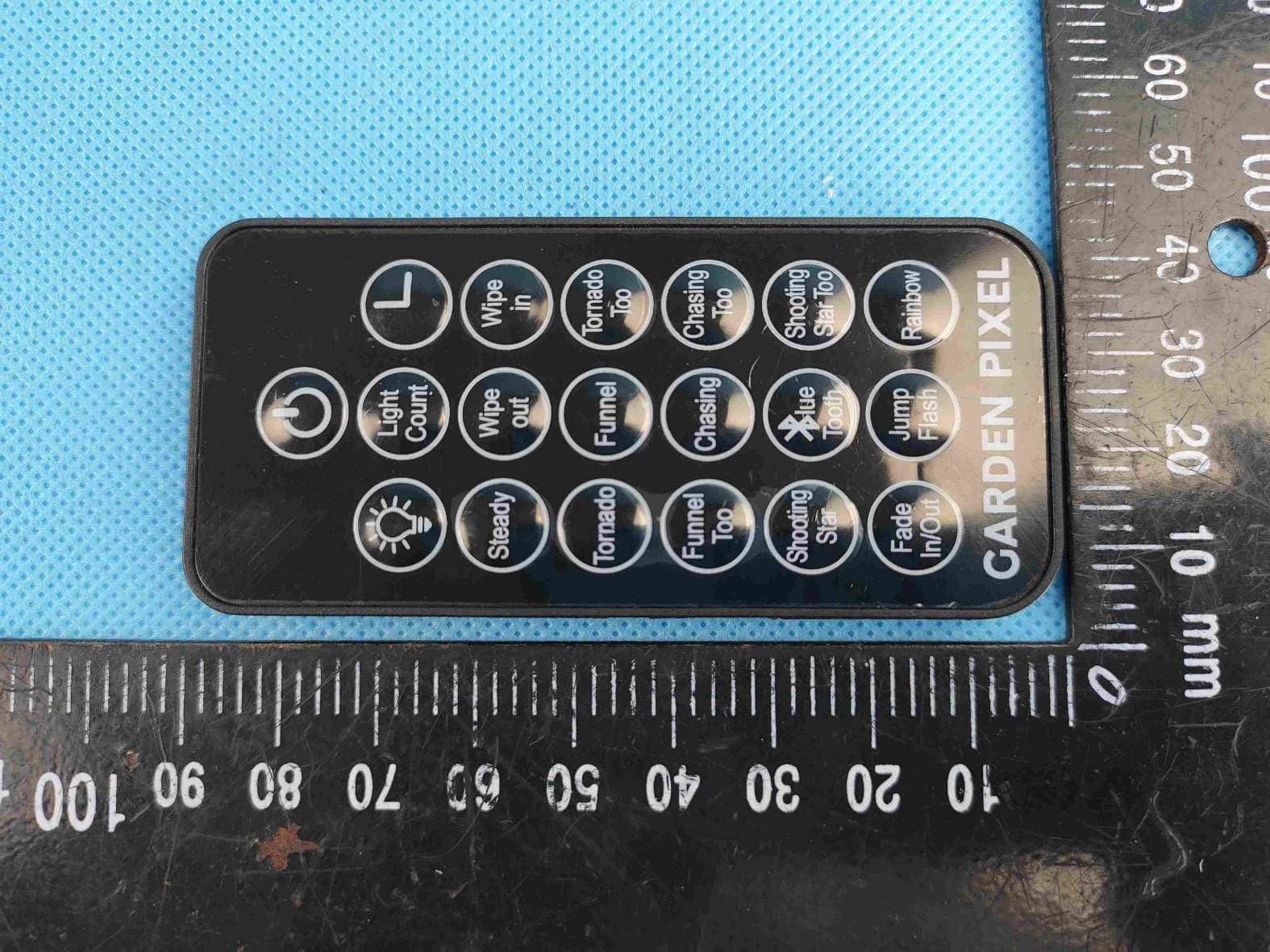
2AEBHPIXEL131
Apr 13, 2020Remote Control Transmitter
Equipment Class
DSC - Part 15 Security/Remote Control Transmitter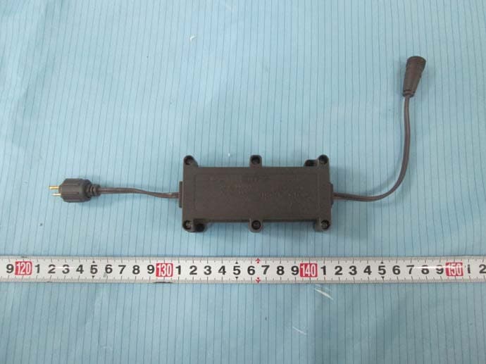
2AEBHR21501B2C
May 24, 2015Control box for light string
Equipment Class
CYY - Communications Receiver used w/Pt 15 Transmitter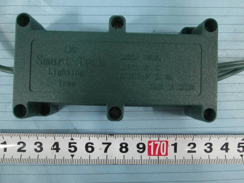
2AEBHR51501B1C
May 24, 2015Control box for light string
Equipment Class
CYY - Communications Receiver used w/Pt 15 Transmitter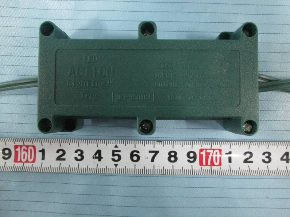
2AEBHR41501B1C
May 21, 2015Control Box for Light String
Equipment Class
CYY - Communications Receiver used w/Pt 15 Transmitter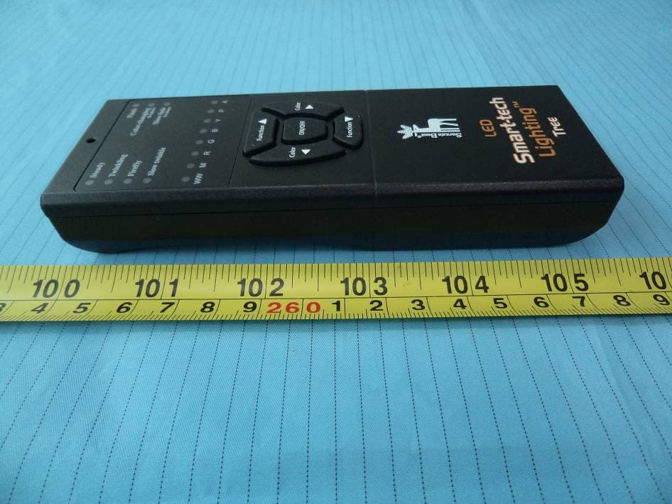
2AEBHR51501B1
Apr 20, 2015Remote Control
Equipment Class
DSC - Part 15 Security/Remote Control Transmitter