2AEBHR41501B1CControl Box for Light String
Guangde Ledup Enterprise Inc.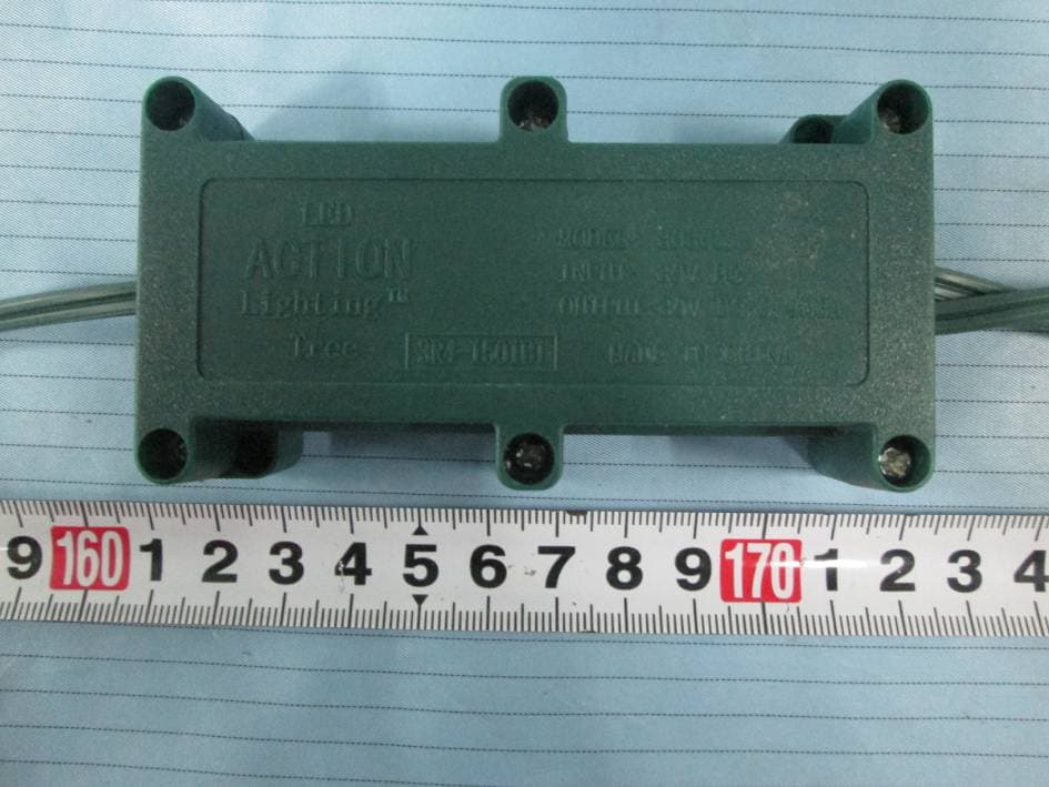
Click to zoom
Application Details
- Equipment Class
- CYY - Communications Receiver used w/Pt 15 Transmitter
- Date of Grant
- May 21, 2015
- Application Purpose
- Original Equipment
- Date of Application
- May 21, 2015
- Equipment Note
- Control Box for Light String
- Frequency Range
- 433.92000000 - 433.92000000
- Country
- China
Documents & Files
Document Text
Text extracted from the exhibit documents filed with the FCC. Open a document above to read the original.
Users Manual
responsible for compliance could void the user's authority to This device complies with part 15 of the FCC Rules. Operation Fig 7 Fig 3 ASSEMBLY OF THE TREE 1. Locate the bottom section of the tree which is identified by a label on the outer branches marked “A” (Fig 5). 2. Remove the protective plastic cap from the end of the pole, (that is pinched to a point), and place that end into the tree stand. Be sure that the pointed end of the pole extends to the bottom of the stand. 3. Now tighten the eyebolts evenly on the tree stand; being careful not to over-tighten (Fig 3). ASSEMBLY INSTRUCTIONS (We recommend wearing proper clothing in order to prevent scratches that may occur during the assembly process.)Carefully unpack the contents from the tree’s carton (Fig 1); including the contents of the poly-bag that is adhered to the interior flap of the tree’s carton.Contained in the poly-bag are RGB replacement bulbs and a remote control which operates your tree's 42 function lighting capability.Your tree should include the following components:A folding metal tree stand with (3) eyebolts.An on/off push button foot pedal with cord and plug (Fig 6); which is pre-attached at the lowest section of your tree (Fig 5). 7.5’ trees will have (3) tree sections; (“A” , “B” and “C”; as shown in Fig 5). Thank you for your purchase of this pre-lit & pre-shaped Christmas tree.With proper use and care, this tree will provide years of trouble-free enjoyment. Please follow the instructions below in order to effectively assemble and disassemble your tree. PRE-LIT & PRE-SHAPED CHRISTMAS TREE ASSEMBLY OF THE TREE STAND 1. Remove the tree stand from the plastic bag, loosen the eye bolt and open the tree stand to form an “X” . 2. Align the holes for the insertion of the remaining (2) eyebolts.3. Insert each eyebolt and begin threading in a clockwise direction for a couple of rotations only; leaving enough room for the tree’s pole from section “A” to be inserted into the assembled stand (Fig 2). 4. Place the tree stand in its desired location; as once the tree is fully assembled, it may be too difficult to move and relocate. Fig 1 4. Carefully cut the nylon strapping bounding the branches upright. CAUTION: Be extremely careful not to cut any of the exposed light set wires. 5. Now gently guide the branches downward into place.6. Beneath the canopy of section “A” , contains an on/off push button foot pedal with cord and plug (Fig 6). Remove the twist-tie binding the cord together and insert the plug into a working electrical outlet. 7. On/off push button foot pedal operation: The on/off push button foot pedal is intended to provide basic manual on/off operation only; and therefore cannot provide the remote control’s 42 function lighting capability. TROUBLESHOOTING 1. If the tree does not illuminate press the on/off button on your remote control. If failure to light persists, the battery may need to be replaced. Insert a standard 9 volt type battery (6F22, 6LR61 or 23F6-220); aligning the appropriate ( +/- ) markings accordingly. NOTE: The tree’s 42 function lighting capability is controlled solely by the use of the remote control provided. If the tree fails to light due to a damaged or defective remote control; please resort to manual on/off push button foot pedal operation until a new remote control can be provided through our customer service center. 2. If failure to light persists, press the on/off push button foot pedal; as it may be in the “Off ” mode. 3. If the top of the tree or another individual lettered section does not illuminate, remove each section and then reinsert as instructed, to ensure the electrical connection is made. NOTE: The tree’s top is designed specifically for a secure and firm connection point. Downward force will be needed to ensure that the electrical connection occurs. 4. Always inspect your tree for any burned out LED/RGB bulbs. Although the tree will continue to remain lit even if a bulb burns out, is loose or is missing; any burned out LED/RGB should be replaced promptly to ensure the performance and life expectancy of your tree. NOTE: Replacement bulbs are provided; this is a specialty LED/RGB bulb. Do not attempt to replace with a standard LED or incandescent bulb. Should you require additional bulbs please contact our customer service department. NOTE: In order to determine which color replacement bulb is needed; select “Steady” function and “Multi” (M) color on your remote control; to determine which color is absent. 5. If there is a delayed response while switching between color selections on the remote control. This is in no way a malfunction of the lighting, but is a normal operating response due to the complexity of the technology. All bulbs must independently receive their signal to alter to the correct color selected. Some bulbs may receive their signals quicker than others, hence a delayed receiver response may occur. Again, this is innate of the technology and a normal response. Made in China Printed in ChinaThis is not a toy, for decorative use only. NOTE: DO NOT USE A DIMMER SWITCH; OR INSTALL ANY ADDITIONAL LIGHTING OR ORNAMENTION THAT IS POW-ERED THROUGH THE LIGHT BULB SOCKETS. DOING THIS MAY RESULT IN DAMAGE TO THE LIGHTING SYSTEM OR MAY CAUSE PERSONAL INJURY; THEREFORE VOIDING THE LIMIT-ED WARRANTY PROVIDED WITH THIS PRODUCT. 1. Gently remove the plug from its electrical outlet, and carefully bind the cord which contains the on/off push button foot pedal and plug. 2. Beginning with the tree’s top section; lift each section straight up from the section below, and continue working downward. NOTE: You may have to slightly wiggle each section as you lift each section upward. 3. To remove the bottom and final section; loosen the eyebolts by turning in a counter-clockwise direction and lift section “A” from the support collar of the tree stand. 4. Gently fold the branches of each section upward, towards the center, and position in the storage container. NOTE: With the except…
Text truncated - open the document above for the full version.
Cover Letter(s)
Guangde Ledup Enterprise Inc. Add: Jingtang Road, Economic Development Zone, Xuancheng City, Anhui Province, China Tel: 0086 18956371120 Fax: 0086 563 6767225 FCC Authorization 2015-4-14 FEDERAL COMMUNICATIONS COMMISSIONS Authorization and Evaluation Division 7435 Oakland Mills Road Columbia, MD 21046 Subject: Agent Authorization To whom it may concern: We, Guangde Ledup Enterprise Inc., the undersigned, hereby authorize Bay Area Compliance Laboratories Corporation to act on its behalf in all matters relating to application for Equipment authorization, including the signing of all documents relating to these matters. All acts carried out by Bay Area Compliance Laboratory Corporation on our behalf shall have the same effect as our own action. We, the undersigned, hereby certify that we are not subject to a denial of federal benefits, that includes FCC benefits, pursuant to Section 5301 of the Anti-Drug Abuse Act of 1988, 21 U.S.C. 862. This authorization is valid until further written notice from the applicant. Sincerely Yours, Signature: Print Name: Lianfeng Ma Title: General Manager QA-FR-170-B
Cover Letter(s)
FCC ID: 2AEBHR41501B1C
Cover Letter(s)
Guangde Ledup Enterprise Inc. Add: Jingtang Road, Economic Development Zone, Guangde, Xuancheng City, Anhui, China Tel: Tel: 0563-6988761 Fax: 0563-6767225 2015-5-11 Product Similarity Declaration To Whom It May Concern, We, Guangde Ledup Enterprise Inc. , hereby declare that we have a product named as Control Box (Model number: 3R4-1501B1 ) was tested by BACL, meanwhile, for our marketing purpose, we would like to list a series models 7R4-1501B1, 7R4-1502B1, 12R4-1501B1, 30R4-1501B1, 11R4- 1501B1, 8R4-1501B1 on reports and certificate, all the models are identical schematics. No other changes are made to them. We confirm that all information above is true, and we’ll be responsible for all the consequences. Please contact me if you have any question. Signature: Printed Name: Lianfeng Ma Title: General Manager
External Photos
EXHIBIT B - EUT EXTERNAL PHOTOGRAPHS EUT – Front View EUT – Rear View EUT – Top View EUT – Bottom View EUT – Left Side View EUT – Right Side View
ID Label/Location Info
EXHIBIT A - FCC ID LABEL AND LOCATION FCC ID Label FCC ID Label Location Information The label shown shall be permanently affixed at a conspicuous location on the device and be readily visible to the user at the time purchase (Labeling requirements per 2.925)
Internal Photos
EXHIBIT C - EUT INTERNAL PHOTOGRAPHS EUT – Cover off View 1 EUT – Main Board Top View EUT – Main Board Bottom View EUT – Rear Board Top View EUT – Main Board Bottom View
Test Report
Note: This test report is prepared for the customer shown above and for the device described herein. It may not be duplicated or used in part without prior written consent from Bay Area Compliance Laboratories Corp. FCC PART 15B, CLASS B TEST REPORT For Guangde Ledup Enterprise Inc. Jingtang Road, Economic Development Zone, Xuancheng City, Anhui Province, China FCC ID: 2AEBHR41501B1C Report Type: Original Report Product Type: control box for light string Test En gineer: Joanna Jiao Re port Number: RSZ150428550-00 Re port Date: 2015-05-05 Reviewed B y: Suny Sun EMC Manager Prepared By: Bay Area Compliance Laboratories Corp. (Shenzhen) 6/F, the 3rd Phase of WanLi Industrial Building ShiHua Road, FuTian Free Trade Zone Shenzhen, Guangdong, China Tel: +86-755-33320018 Fax: +86-755-33320008 www.baclcorp.com.cn Bay Area Compliance Laboratories Corp. (Shenzhen) Report No.: RSZ150428550-00 FCC Part 15B, Class B Page 2 of 16 TABLE OF CONTENTS GENERAL INFORMATION ....................................................................................................................................... 3 PRODUCT DESCRIPTION FOR EQUIPMENT UNDER TEST (EUT) ..................................................................................... 3 OBJECTIVE ................................................................................................................................................................... 3 RELATED SUBMITTAL(S)/GRANT(S) ............................................................................................................................. 3 TEST FACILITY ............................................................................................................................................................. 3 SYSTEM TEST CONFIGURATION .......................................................................................................................... 4 DESCRIPTION OF TEST CONFIGURATION ...................................................................................................................... 4 EUT EXERCISE SOFTWARE .......................................................................................................................................... 4 SPECIAL ACCESSORIES ................................................................................................................................................. 4 EQUIPMENT MODIFICATIONS ....................................................................................................................................... 4 SUPPORT EQUIPMENT LIST AND DETAILS .................................................................................................................... 4 EXTERNAL I/O CABLE .................................................................................................................................................. 4 BLOCK DIAGRAM OF TEST SETUP ................................................................................................................................ 5 SUMMARY OF TEST RESULTS ............................................................................................................................... 6 FCC §15.107 – AC LINE CONDUCTED EMISSIONS ............................................................................................. 7 APPLICABLE STANDARD .............................................................................................................................................. 7 MEASUREMENT UNCERTAINTY .................................................................................................................................... 7 EUT SETUP .................................................................................................................................................................. 7 EMI TEST RECEIVER SETUP ......................................................................................................................................... 8 TEST PROCEDURE ........................................................................................................................................................ 8 TEST EQUIPMENT LIST AND DETAILS ........................................................................................................................... 8 CORRECTED FACTOR & MARGIN CALCULATION ......................................................................................................... 8 TEST RESULTS SUMMARY ............................................................................................................................................ 9 TEST DATA .................................................................................................................................................................. 9 FCC §15.109 - RADIATED SPURIOUS EMISSIONS ............................................................................................ 12 APPLICABLE STANDARD ............................................................................................................................................ 12 MEASUREMENT UNCERTAINTY .................................................................................................................................. 12 EUT SETUP ................................................................................................................................................................ 12 EMI TEST RECEIVER SETUP ....................................................................................................................................... 13 TEST PROCEDURE ...................................................................................................................................................... 13 TEST EQUIPMENT LIST AND DETAILS ......................................................................................................................... 13 CORRECTED AMPLITUDE & MARGIN CALCULATION ...................................…
Text truncated - open the document above for the full version.
Test Setup Photos
EXHIBIT D - TEST SETUP PHOTOGRAPHS Conducted Emissions - Front View Conducted Emissions - Side View Radiated Emissions – Front View (Below 1 GHz) Radiated Emissions – Rear View (Below 1 GHz) Radiated Emissions – Front View (Above 1 GHz) Radiated Emissions – Rear View (Above 1 GHz)
Contact Information
Applicant
Lianfeng Ma
Test Firm
Bay Area Compliance Laboratory Corp. (Shenzhen)John Chan
Technical Specifications
| # | Rule Parts | Frequency Range | Power Output |
|---|---|---|---|
| 1 | 15B | 433.92 MHz - 433.92 MHz | - |
Other Applications from Guangde Ledup Enterprise Inc.
2AEBHAR2101B1
Mar 10, 2021Remote Control Transmitter
Equipment Class
DXX - Part 15 Low Power Communication Device Transmitter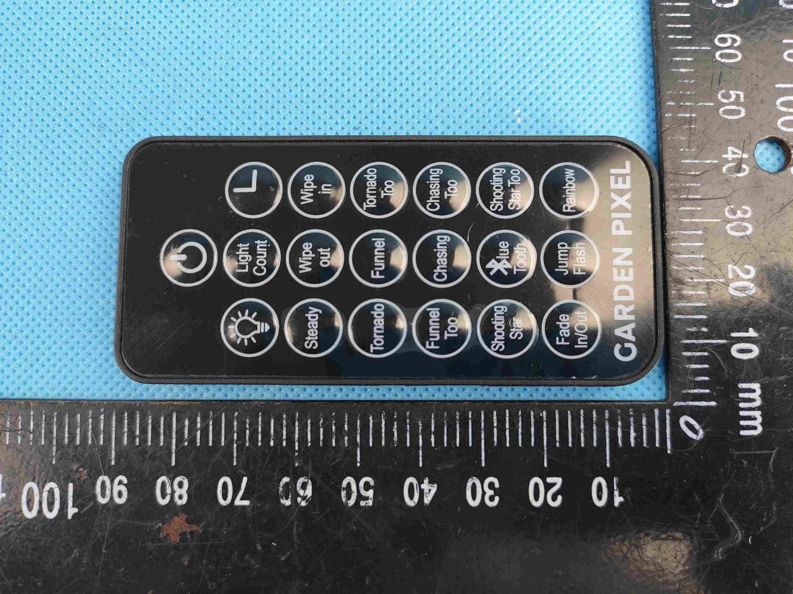
2AEBHPIXEL131
Apr 13, 2020Remote Control Transmitter
Equipment Class
DSC - Part 15 Security/Remote Control Transmitter
2AEBHR21501B2C
May 24, 2015Control box for light string
Equipment Class
CYY - Communications Receiver used w/Pt 15 Transmitter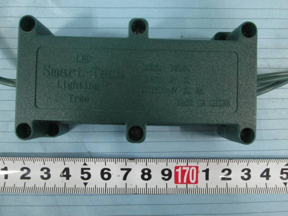
2AEBHR51501B1C
May 24, 2015Control box for light string
Equipment Class
CYY - Communications Receiver used w/Pt 15 Transmitter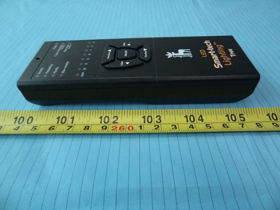
2AEBHR51501B1
Apr 20, 2015Remote Control
Equipment Class
DSC - Part 15 Security/Remote Control Transmitter