2AEBHPIXEL131Remote Control Transmitter
Guangde Ledup Enterprise Inc.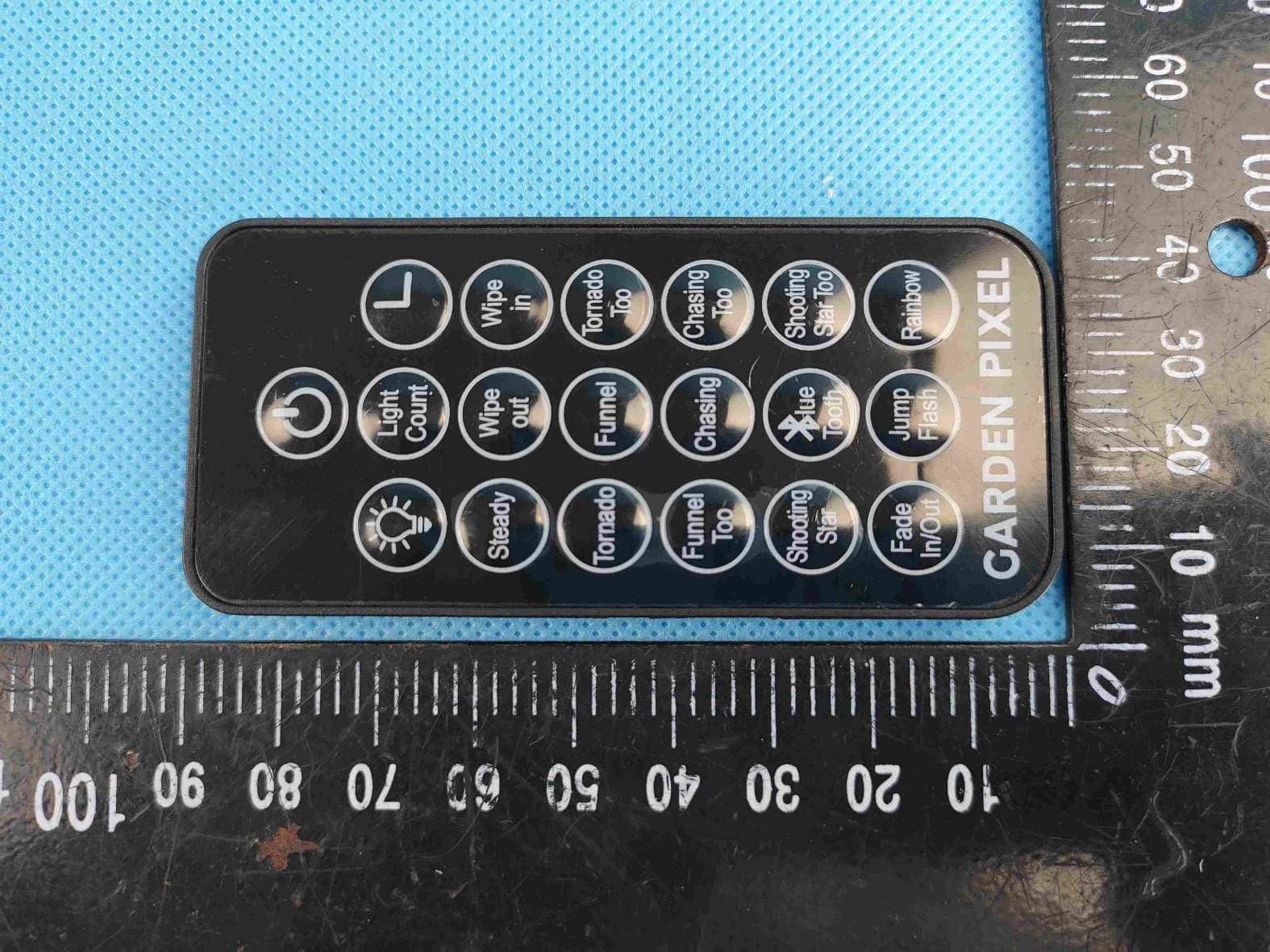
Click to zoom
Application Details
- Equipment Class
- DSC - Part 15 Security/Remote Control Transmitter
- Date of Grant
- Apr 13, 2020
- Application Purpose
- Original Equipment
- Date of Application
- Apr 13, 2020
- Equipment Note
- Remote Control Transmitter
- Frequency Range
- 433.92000000 - 433.92000000
- Country
- China
Documents & Files
Document Text
Text extracted from the exhibit documents filed with the FCC. Open a document above to read the original.
Users Manual
LED20 ASSEMBLY INSTRUCTIONS: No tools required. Retain carton for storage. 1. Carefully remove all parts from the carton. Your Garden Pixel Lights should include the following (Fig 1): • 15 pcs staked Garden Pixel Lights • 1 control box with speaker • 1 remote control 1. Leave assembled if storage room permits or disassemble, placing all components in the original carton. 2. Store in cool, dry location away from sunlight. DISASSEMBLY & STORAGE 2. Remove the protective caps (Fig 2a & 2b). 3. In your desired location; begin to position your 15 pc staked Garden Pixel Lights; spacing accordingly to your prefered placement & design. Grasp each staked Garden Pixel Light near the lowest point possible and push downward into the ground (Fig 3a). NOTE: Each Garden Pixel Light has 36” of spacing wire. 4. Now place your control box with speaker in a position in order to direct the sound to your desired location. Position and push downward into the ground (Fig 3b). 5. To illuminate; insert the plug into a working GFCI outlet or an outdoor rated extension cord. Made in China Printed in China This is not a toy, for decorative use only. Please follow the instructions below in order to properly assemble and store your Garden Pixel Lights. GARDEN PIXEL LIGHTS Fig 1 Remote Control Control box with Speaker 15 pcs staked Garden Pixel set Fig 2a Fig 2b Fig 3a Fig 3b 6. You have completed the installation of the Garden Pixel Lights set (Fig 4). Fig 4 REMOTE CONTROL OPERATION Your 15 Garden Pixel Light’s 131 Function capability is controlled solely by the use of the remote control provided (Fig 5). A CR2025 Battery is included within the remote control. Before operating the remote; remove the thin plastic film that has been inserted - by slightly pulling downward away from the lower portion of the remote control. ✓ ✓ ✓ ✓ ✓ ✓ ✓ ✓ ✓ ✓ ✓ ✓ ✓ ✓ ✓ ✓ ✓ ✓ ✓ ✓ ✓ ✓ ✓ ✓ ✓ ✓ ✓ ✓ ✓ ✓ ✓ ✓ ✓ ✓ ✓ ✓ ✓ ✓ ✓ ✓ ✓ ✓ ✓ ✓ ✓ ✓ ✓ ✓ ✓ ✓ ✓ ✓ ✓ ✓ ✓ ✓ ✓ ✓ ✓ ✓ ✓ ✓ ✓ ✓ ✓ ✓ ✓ ✓ ✓ ✓ ✓ ✓ ✓ ✓ ✓ ✓ ✓ ✓ ✓ ✓ ✓ ✓ ✓ ✓ ✓ ✓ ✓ ✓ ✓ ✓ ✓ ✓ ✓ ✓ ✓ ✓ ✓ ✓ ✓ ✓ ✓ ✓ ✓ ✓ ✓ ✓ ✓ ✓ ✓ ✓ ✓ ✓ ✓ ✓ ✓ ✓ ✓ ✓ ✓ ✓ ✓ ✓ ✓ ✓ ✓ ✓ ✓ ✓ ✓ ✓ ✓ 1. Red 2. Green 3. Blue 4. Purple 5. Yellow 6. Teal 7. Warm White 8. Multi 3 Color 9. Multi 7 Color 10. Multi 15 Color Total no. of functions SteadyWipe Out Wipe In TornadoFunnelTornado Too Funnel Too Chasing 1010101010101010101010 Chasing Too Shooting Star Shooting Star Too 10101 Fade In/ Out Jump Flash RainbowColor / Function 131 LIGHTING COMBINATIONS: Funnel Wipe out Light Count Tornado Rainbow Tornado To o Steady Wipe in Chasing Chasing To o Funnel To o Shooting Star Fade In/Out Jump Flash Shooting Star Too GARDEN PIXEL lue Tooth Fig 5 SPECIAL FEATURES: BRIGHTNESS CONTROL: • Press the “Brightness” button 5 times; to achieve your preferred level of brightness – Select either a low, medium or high brightness level. NOTE: Only the “Steady” function has this brightness control capability. TIMER FEATURE: • Press the “Timer” button; the lights will flash GREEN 3 times – Indicating that the 6 hour “On” / 18 hour “Off” timer has now been activated. • Note: The lights will automatically resume back to the “On” position – 24 hours from when it was initially activated. • Press the “Timer” button again, the lights will flash RED 3 times – Indicating that the timer feature has now been deactivated. lue Tooth BLUE TOOTH: • In order for your Garden Pixel Lights to synchronise with your phone’s music selections; first press the “Blue Tooth” button located on the remote control provided. Located in the “Settings” section of your phone; select “Blue Tooth”, select device “LED_UP” in order to connect. Once connected; make your music selection accordingly. 1. If the Garden Pixel Light does not illuminate press the on/off button on your remote control. If failure to light persists, the battery within the remote control, may need to be replaced. Insert a standard CR2025 battery. NOTE: The 15 Garden Pixel Light’s 131 function lighting capability is controlled solely by the use of the remote control provided. NOTE: By reducing the distance from your Garden Pixel Lights; you may achieve better remote control reception. 2. If an individual Garden Pixel Light fails to light; you are able to remove said light by unthreading the coaxial connections. You can then reconnect the Garden Pixel Lights that are still operating, again, by the male and female coaxial connections (Fig 6). TROUBLESHOOTING Fig 6 Light Count LIGHT COUNT: 2 special pattern programs have been installed into your 15 pc Garden Pixel Light Set. NOTE: An additional 2 special pattern programs are available upon connecting a second 15 pc Garden Pixel Set. When you press the Light Count button, blue lights will flash once; indicating that the 1st special pattern has now been activated. When you press the Light Count button again, blue lights will flash twice; indicating that the 2nd special pattern has now been activated. Upon a second 15 pc Garden Pixel Light Set being added-on; a third and fourth special pattern program is now available. NOTE: The maximum connect-ability of your 15 pc Garden Pixel Light Set is (2) sets. A total of 30 Garden Pixel Lights. Light Count Light Count Pattern 1 (1 x 15) Pattern 3 (3 x 5) Pattern 4 (5 x 6) Pattern 2 (2 x 15) 15” 11.5” 2020 QVC Garden Pixel Lights - 131 Function RGB - Instruction Sheet (English) Date: 3/18/2020 This device complies with Industry Canada’s license-exempt RSSs. Operation is subject to the (1) This device may not cause interference; and (2) this device must accept any interference, including interference that may cause undesired operation of the device. following two conditions: Le présent appareil est conforme aux CNR d'Industrie Canada applicables aux appareils radio exempts de licence. L'exploitation est autorisée aux deux conditions suivantes: (1) l'appareil ne doit pas produire de brouillage, et (2) l'utilisateur de l'appareil doit accepter tout brouillage radioélectrique subi, même si le brouillage est susceptible d'en compromettre le fonctionne…
Text truncated - open the document above for the full version.
External Photos
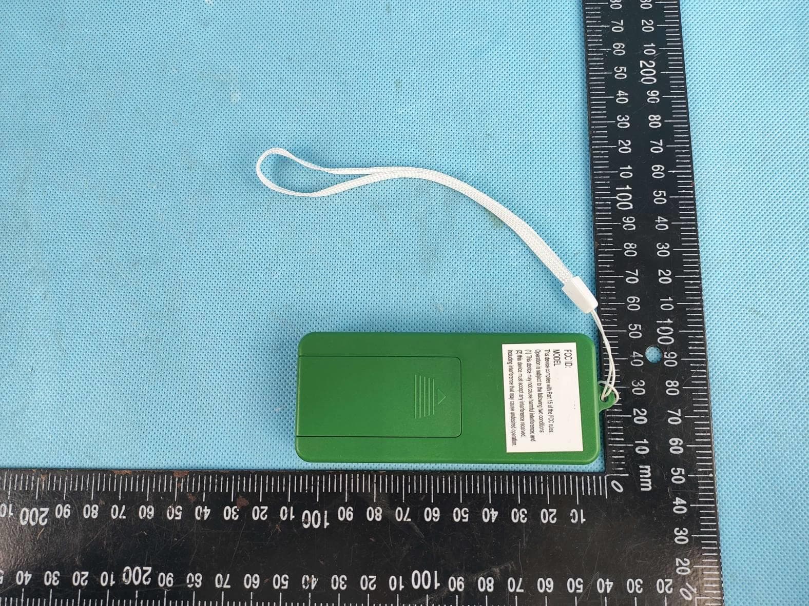
Page 1 of 4 External PHOTO: Model: PIXEL-131 Page 2 of 4 Page 3 of 4 Page 4 of 4
Internal Photos
Page 1 of 2 Internal PHOTO: Model: PIXEL-131 Antenna Page 2 of 2
Test Report
ITL Page 1 of 26 Report No.: D200109001 TEST REPORT Applicant: Guangde Ledup Enterprise, Inc. Address of Applicant: Jingtang Road, Guangde Economic Development Zone, Guangde, Anhui, China Manufacturer: Guangde Ledup Enterprise, Inc. Address of Manufacturer: Jingtang Road, Guangde Economic Development Zone, Guangde, Anhui, China Product name: Remote control Model: PIXEL-131 Rating(s): 3Vdc Trademark: LEDUP Standards: 47 CFR PART 15 Subpart C: section 15.231 FCC register number: 239076 FCC ID: 2AEBHPIXEL131 Data of Receipt: 2020-01-06 Date of Test: 2020-01-06~2020-03-27 Date of Issue: 2020-03-27 Test Result Pass* * In the configuration tested, the test item complied with the standards specified above. Authorized for issue by: Test by: Reviewed by: Mar.27, 2020 Eleven Liang Mar.27, 2020 Pauler Li Project Engineer Project Engineer Date Name/Position Signature DateName/Position Signature ITL Page 2 of 26 Report No.: D200109001 Possible test case verdicts: test case does not apply to the test object .. : N/A test object does meet the requirement ........ : P (Pass) test object does not meet the requirement .. : F (Fail) Testing Laboratory information: Testing Laboratory Name .......... : ITL Co., Ltd. Address : No.8, JinQianLing street 5, DongHuan Road, Huangjiang Town, Dongguan, China. Testing location : Same as above Tel : 0086-769-39001678 Fax : 0086-20-62824387 E-mail : [email protected] General remarks: The test results presented in this report relate only to the object tested. The results contained in this report reflect the results for this particular model and serial number. It is the responsibility of the manufacturer to ensure that all production models meet the intent of the requirements detailed within this report. This report would be invalid test report without all the signatures of testing technician and approver. This report shall not be reproduced, except in full, without the written approval of the Issuing testing laboratory. General product information: / ITL Page 3 of 26 Report No.: D200109001 1 Test Summary Test Test Requirement Test method Result Radiated Emission FCC PART 15 section 15.231(b) ANSI C 63.10: Clause 6.4, 6.5 and 6.6 PASS Occupied Bandwidth FCC PART 15 section 15.231(c) ANSI C 63.10: Clause 6.9 PASS Dwell Time FCC PART 15 section 15.231(a) FCC PART 15: Section 15.231(a) PASS Conducted Emission RSS-Gen Issue 4 / N/A Remark: N/A: because the device is battery operated. EUT: In this whole report EUT means Equipment Under Test. Tx: In this whole report Tx (or tx) means Transmitter. Rx: In this whole report Rx (or rx) means Receiver. RF: In this whole report RF means Radio Frequency. ANSI C63.10: the detail version is ANSI C63.10:2013 in the whole report. ITL Page 4 of 26 Report No.: D200109001 2 Contents TEST REPORT ....................................................................................................................................................................... 1 1 TEST SUMMARY ......................................................................................................................................................... 3 2 CONTENTS ................................................................................................................................................................... 4 3 GENERAL INFORMATION ........................................................................................................................................ 5 3.1 CLIENT INFORMATION ............................................................................................................................................ 5 3.2 GENERAL DESCRIPTION OF E.U.T. ....................................................................................................................... 5 3.3 DETAILS OF E.U.T. ................................................................................................................................................ 5 3.4 DESCRIPTION OF SUPPORT UNITS ........................................................................................................................ 5 3.5 TEST LOCATION ..................................................................................................................................................... 6 3.6 DEVIATION FROM STANDARDS .............................................................................................................................. 6 3.7 ABNORMALITIES FROM STANDARD CONDITIONS .................................................................................................. 6 3.8 OTHER INFORMATION REQUESTED BY THE CUSTOMER ....................................................................................... 6 3.9 TEST FACILITY ....................................................................................................................................................... 6 3.10 MEASUREMENT UNCERTAINTY .............................................................................................................................. 6 4 INSTRUMENTS USED DURING TEST .................................................................................................................... 7 5 TEST RESULTS ........................................................................................................................................................... 8 5.1 E.U.T. TEST CONDITIONS ...................................................................................................................................... 8 5.2 RADIATED EMISSIONS ........................................................................................................................................... 9 5.3 OCCUPIED BANDWIDTH ....................................................................................................................................... 19 5.4 DWELL TIME .................................................................................................................…
Text truncated - open the document above for the full version.
Test Setup Photos
Page 1 of 2 TEST PHOTO: Page 2 of 2
Contact Information
Applicant
Lianfeng Ma
Technical Contact
ITL Co., LtdPauler Li
[email protected]0086-769-39001678
No. 8 Jinqianling Street 5 · Dongguan · China
Test Firm
ITL Co., LTDBob Dai
Technical Specifications
| # | Rule Parts | Frequency Range | Power Output |
|---|---|---|---|
| 1 | 15.231 | 433.92 MHz - 433.92 MHz | - |
Other Applications from Guangde Ledup Enterprise Inc.
2AEBHAR2101B1
Mar 10, 2021Remote Control Transmitter
Equipment Class
DXX - Part 15 Low Power Communication Device Transmitter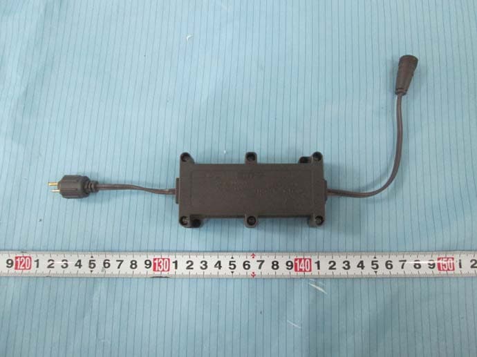
2AEBHR21501B2C
May 24, 2015Control box for light string
Equipment Class
CYY - Communications Receiver used w/Pt 15 Transmitter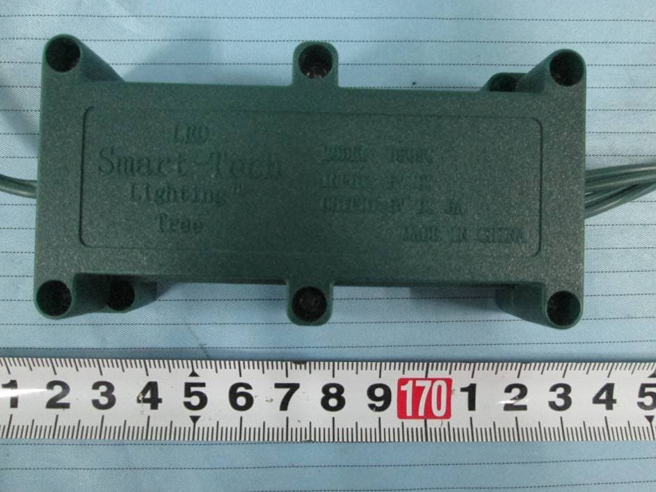
2AEBHR51501B1C
May 24, 2015Control box for light string
Equipment Class
CYY - Communications Receiver used w/Pt 15 Transmitter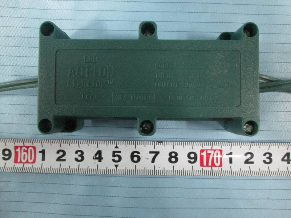
2AEBHR41501B1C
May 21, 2015Control Box for Light String
Equipment Class
CYY - Communications Receiver used w/Pt 15 Transmitter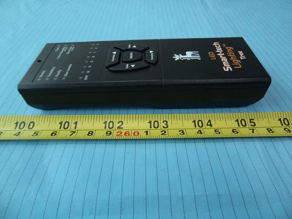
2AEBHR51501B1
Apr 20, 2015Remote Control
Equipment Class
DSC - Part 15 Security/Remote Control Transmitter