2AEFTAW310RSmart Microphone
AVerMedia Technologies, Inc.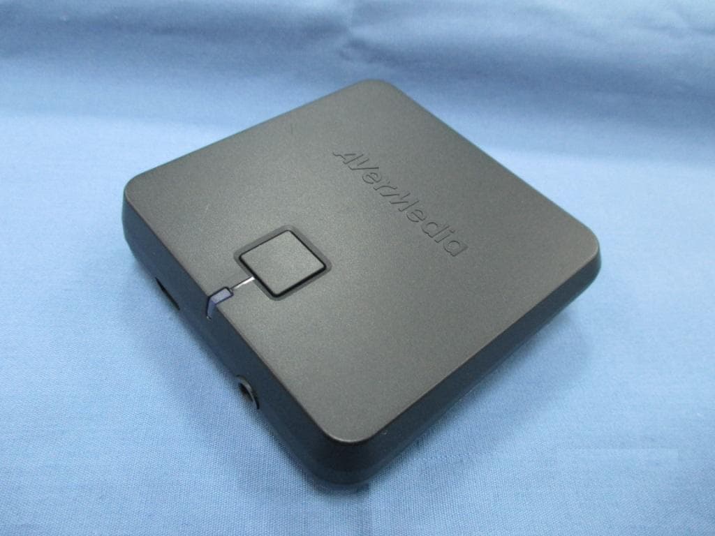
Click to zoom
Application Details
- Equipment Class
- DSS - Part 15 Spread Spectrum Transmitter
- Date of Grant
- Apr 21, 2015
- Application Purpose
- Original Equipment
- Date of Application
- Apr 21, 2015
- Equipment Note
- Smart Microphone
- Frequency Range
- 2406.00000000 - 2474.00000000
- Company
- AVerMedia Technologies, Inc.
- Country
- Taiwan
Documents & Files
Document Text
Text extracted from the exhibit documents filed with the FCC. Open a document above to read the original.
Users Manual
1 Connect the receiver to a power outlet. 2 Connect the receiver to a mic. input. Press the Power button. 3 T urn on the microphone and start using.* Installation 12 MIC IN Note: To avoid excessive sound on initial sound test, lower your audio system volume first. * If both Power LEDs continue to flash, re-synchronize the microphone and receiver by pressing both power buttons simultaneously for 3 seconds and wait until the LEDs turn solid. 3 Quick Guide In the Box Microphone Receiver USB AC Adapter Receiver Press and hold 3 sec t o synchronize. Press to turn On/Off. 1 2 3 4 POWER MIC OUT USB power jack 2 Power LED 3 3.5 mm mic. out jack 4 Power button 1 Power LED Solid: On Flashing: Synchronizing Power LED Solid: On Flashing: Synchronizing 5 4 6 7 4 Sound inlet 5 USB power jack 6 Lanyard hole 7 Clip Microphone 1 2 3 3 P ower LED 2 Battery LED Multi-function switch 1 2 3 Volume Up Volume Down Press: On/Off Hold 3s: Synchronize USB Power Cable 3.5 mm to 6.3 mm Audio Cable Carrying Bag Lanyard Quick Guide Smart Microphone AW310 Clip Form 1 Rot at e the clip. 2 Clip it on. Pendant Form 1 Remove the clip. 3 Place it around your neck. 2 Attach the lanyard. English -9 English -10 www.avermedia.com Note: Fully charge your microphone before first use. Charging Solid: Charging Off: Fully Charged Flashing: Low Battery Battery LED English -1 English -2English-3English-4English -5 English -6English -7 English -8 Français -1 Français -2 Quick Guide Contenu de la Boîte Microphone Adaptateur USB AC Récepteur Guide Utilisateur Câble Alimentation USB Câble Audio 3.5mm vers 6.3mm Sac de Transport Cordon M o d e l N o . : A W3 1 0 P / N 3 0 0 A A W3 1 0 D 7 B Ma d e i n T a i w a n Français -9 Français -10 Français -3Français -4Français -5 Français -6Français -7Français -8 4 5 6 7 Microphone 4 Tête de micro 5 Jack alimentation USB 6 Trou cordon 7 Clip Récepteur Presser et Appuyer 3 sec pour synchroniser. Presser pour On/Off. 1 2 3 4 1 2 3 3 Alimentation LED 2 Batterie LED Switch multi fonction 1 Connecter le récepteur à une source d'alimentation. 2 Connecter le récepteur à une entrée micro. Appuyer sur le bouton marche. 3 Allumer le micro et commencer l'utilisation.* Installation 12 MIC IN Remarque: pour éviter un volume sonore excessif lors de votre premier test de son, veuillez diminuer le son sur votre système audio. * Si les deux LEDs d'alimentation continuent à clignoter, re-synchroniser le microphone et le récepteur en appuyant sur les 2 boutons d'alimentation simultanément pendant 3 secondes, et attendre que les LEDs arrêtent de clignoter. 3 Remarque: Charger complètement votre microphone avant la première utilisation. Mise en Charge Constant: En Charge Eteint: Entièrement chargé Clignote: Batterie Faible Batterie LED POWER MIC OUT Bouton alimentation 1 Jack alimentation USB 2 LED alimentation 3 Jack micro 3.5mm 4 1 2 3 Alimentation LED Constant: On Clignotant: Synchronisation Alimentation LED Constant: On Clignotant: Synchronisation Volume Fort Volume Faible Presser: On/Off Appuyer 3s: Synchroniser Clip Form 1 Tourner le clip. 2 Accrocher-le à la veste. Pendentif 1 Enlever le clip. 3 Placer le autour du cou. 2 Attacher le cordon. Disclaimer All the screen shots in this documentation are only example images. The images may vary depending on the product and software version. Information presented in this documentation has been carefully checked for reliability; however, no responsibility is assumed for inaccuracies. The information contained in this documentation is subject to change without notice. ©2015 by AVerMedia Technologies, Inc. All rights reserved. No part of this publication, in whole or in part, may be reproduced, transmitted, transcribed, altered or translated into any language in any form by any means without the written permission of AVerMedia Technologies, Inc. Information and specification contained in this manual are subject to change without notice and do not represent a commitment on the part of AVerMedia. For more information, please refer to www.avermedia.com. "AVerMedia" is a trademark or registered trademark of AVerMedia Technologies, Inc.The pictures contained in this manual are provided for reference purposes only. Made in Taiwan (Except Accessories). US Office Address: 47358 Fremont Blvd., Fremont, CA 94538 Website: www.avermedia-usa.com Telephone: (408)-263-3828 Headquarters Address: No.135, Jian 1st Rd., Zhonghe Dist., New Taipei City 23585, Taiwan Website: www.avermedia.com Telephone: 886-2-2226-3630 v1.0 03/2015 AVerMedia (or its authorized service centers); - Failure to adhere to user’s manual. - Product that are operated in combination with third party’s software which may be obtained by user or provided by AVerMedia in the product packaging. - Product that are operated in combination with third party’s device(s)/equipment(s), or the damage is caused from computer viruses - Damage caused by (a) misuse, abuse, neglect, improper use of the physical or operating environment (such as the exterior ruptures, moisture, exposure to temperature, high or low humidity, power overload, placement subject to extreme environments that include a lack of ventilation or stacking, throwing, soakage, etc.) or modification; (b) improper or unauthorized installation, wiring, repair, testing; (c) use of the Product outside AVerMedia published guidelines; (d) accident, fire, acts of God or force majeure such as natural disasters, environmental distress, or lightning; power surges; (e)improper maintenance or failure to use the information content in accordance with the Product. - Other than the above, similar circumstances not attributable to AVerMedia. Warranty Period The term of the warranty begins from the date of purchase. Your dated sales receipt showing the date of purchase is the proof of purchase. The warranty period varies by product and is generally 1 or 2 years; consult your original AVerMedia product packaging or user information provided by AVerMedia and local in-country distributo…
Text truncated - open the document above for the full version.
Cover Letter(s)
Date: 2015‐04‐02 FCC ID: 2AEFTAW310R AUTHORIZATION LETTER To whom it may concern: We, the undersigned, hereby authorize Amanda Wu/ Senior Specialist of Bureau Veritas Consumer Products Services (H.K.) Ltd., Taoyuan Branch (BV CPS Taoyuan) of Taiwan to act on our behalf in all manners relating to FCC application for equipment authorization, including signing of all documents relating to these matters. Any and all acts carried out by Amanda Wu/ Senior Specialist of BV CPS Taoyuan on our behalf shall have the same effect as acts of our own. If you have any questions regarding the authorization, please don’t hesitate to contact us. Sincerely yours, ‐‐‐‐‐‐‐‐‐‐‐‐‐‐‐‐‐‐‐‐‐‐‐‐‐‐‐‐‐‐‐‐‐‐‐ Name: Ken Yang Title: Technical Supervisor Tel: +886‐2‐2226‐3630 Fax: +886‐2‐2221‐1901 E‐mail: [email protected]
Cover Letter(s)
Date: 2015‐04‐02 FCC ID: 2AEFTAW310R To the attention of Federal Communications Commission Authorization and Evaluation Division Confidentiality Request Pursuant to Sections 0.457 and 0.459 of the Commission’s Rules, the Applicant hereby requests confidential treatment of information accompanying this Application as outlined below: Schematics Block Diagram The above materials contain trade secrets and proprietary information not customarily released to the public. The public disclosure of these matters might be harmful to the Applicant and provide unjustified benefits to its competitors. The Applicant understands that pursuant to Rule 0.457, disclosure of this Application and all accompanying documentation will not be made before the date of the Grant for this application. Sincerely yours, ‐‐‐‐‐‐‐‐‐‐‐‐‐‐‐‐‐‐‐‐‐‐‐‐‐‐‐‐‐‐‐‐‐‐‐ Name: Ken Yang Title: Technical Supervisor Tel: +886 ‐2‐2226‐3630 Fax: +886‐2‐2221‐1901 E‐mail: [email protected]
External Photos
Page 1 CONSTRUCTION PHOTOS OF EUT Page 2 Page 3 Page 4
ID Label/Location Info
FCC Label Location
Internal Photos
Page 5 Page 6 Page 7 Page 8 Page 9
Operational Description
FCC ID: 2AEFTAW310R Report No.: RF150319D07 Operational Description This device is a SMART MICROPHONE. The transmitter of the EUT is powered by 5Vdc from adapter. The antenna is PCB antenna without antenna connector. The other instruction, please have a look at the users manual.
RF Exposure Info
Report No.: SA150319D07 Page No. 1 / 6 Report Format Version: 6.1.1 RF Exposure Report Report No.: SA150319D07 FCC ID: 2AEFTAW310R Test Model: AW310R Received Date: Mar. 16, 2015 Test Date: Mar. 16 ~ Apr. 2, 2015 Issued Date: Apr. 9, 2015 Applicant: AVerMedia Technologies Inc. Address: NO.135, Jian 1st Rd., Zhonghe Dist, New Taipei City, Taiwan (R.O.C.) Issued By: Bureau Veritas Consumer Products Services (H.K.) Ltd., Taoyuan Branch Lab Address: No. 47-2, 14th Ling, Chia Pau Vil., Lin Kou Dist., New Taipei City, Taiwan (R.O.C.) This report is for your exclusive use. Any copying or replication of this report to or for any other person or entity, or use of our name or trademark, is permitted only with our prior written permission. This report sets forth our findings solely with respect to the test samples identified herein. The results set forth in this report are not indicative or representative of the quality or characteristics of the lot from which a test sample was taken or any similar or identical product unless specifically and expressly noted. Our report includes all of the tests requested by you and the results thereof based upon the information that you provided to us. You have 60 days from date of issuance of this report to notify us of any material error or omission caused by our negligence, provided, however, that such notice shall be in writing and shall specifically address the issue you wish to raise. A failure to raise such issue within the prescribed time shall constitute your unqualified acceptance of the completeness of this report, the tests conducted and the correctness of the report contents. Unless specific mention, the uncertainty of measurement has been explicitly taken into account to declare the compliance or non-compliance to the specification. Report No.: SA150319D07 Page No. 2 / 6 Report Format Version: 6.1.1 Table of Contents Release Control Record ............................................................................................................................. 3 1 Certificate of Conformity ................................................................................................................. 4 2 RF Exposure .................................................................................................................................... 5 2.1 Limits For Maximum Permissible Exposure (MPE) .......................................................................... 5 2.2 MPE Calculation Formula ............................................................................................................... 5 2.3 Classification .................................................................................................................................. 5 3 Calculation Result Of Maximum Conducted Power ....................................................................... 6 Report No.: SA150319D07 Page No. 3 / 6 Report Format Version: 6.1.1 Release Control Record Issue No. Description Date Issued SA150319D07 Original release. Apr. 9, 2015 Report No.: SA150319D07 Page No. 4 / 6 Report Format Version: 6.1.1 1 Certificate of Conformity Product: SMART MICROPHONE Brand: AVerMedia Test Model: AW310R Sample Status: Engineering sample Applicant: AVerMedia Technologies Inc. Test Date: Mar. 16 ~ Apr. 2, 2015 Standards: FCC Part 2 (Section 2.1091) KDB 447498 D03 IEEE C95.1 The above equipment has been tested by Bureau Veritas Consumer Products Services (H.K.) Ltd., Taoyuan Branch, and found compliance with the requirement of the above standards. The test record, data evaluation & Equipment Under Test (EUT) configurations represented herein are true and accurate accounts of the measurements of the sample’s EMC characteristics under the conditions specified in this report. Prepared by : , Date: Apr. 9, 2015 Celia Chen / Senior Specialist Approved by : , Date: Apr. 9, 2015 Rex Lai / Assistant Manager Report No.: SA150319D07 Page No. 5 / 6 Report Format Version: 6.1.1 2 RF Exposure 2.1 Limits For Maximum Permissible Exposure (MPE) Frequency Range (MHz) Electric Field Strength (V/m) Magnetic Field Strength (A/m) Power Density (mW/cm 2 ) Average Time (minutes) Limits For General Population / Uncontrolled Exposure 300-1500 ... ... F/1500 30 1500-100,000 ... ... 1.0 30 F = Frequency in MHz 2.2 MPE Calculation Formula Pd = (Pout*G) / (4*pi*r 2 ) where Pd = power density in mW/cm 2 Pout = output power to antenna in mW G = gain of antenna in linear scale Pi = 3.1416 R = distance between observation point and center of the radiator in cm 2.3 Classification The antenna of this product, under normal use condition, is at least 20cm away from the body of the user. So, this device is classified as Mobile Device. Report No.: SA150319D07 Page No. 6 / 6 Report Format Version: 6.1.1 3 Calculation Result Of Maximum Conducted Power Frequency Band (MHz) Max Power (dBm) Antenna Gain (dBi) Distance (cm) Power Density (mW/cm 2 ) Limit (mW/cm 2 ) 2406-2474 7.42 0.46 20 0.0012 1 --- END ---
Test Report
Report No.: RF150319D07 Page No. 1 / 38 Report Format Version: 6.1.1 FCC Test Report Report No.: RF150319D07 FCC ID: 2AEFTAW310R Test Model: AW310R Received Date: Mar. 16, 2015 Test Date: Mar. 16 ~ Apr. 2, 2015 Issued Date: Apr. 9, 2015 Applicant: AVerMedia Technologies Inc. Address: NO.135, Jian 1st Rd., Zhonghe Dist, New Taipei City, Taiwan (R.O.C.) Issued By: Bureau Veritas Consumer Products Services (H.K.) Ltd., Taoyuan Branch Lab Address: No. 47-2, 14th Ling, Chia Pau Vil., Lin Kou Dist., New Taipei City, Taiwan (R.O.C.) This report is for your exclusive use. Any copying or replication of this report to or for any other person or entity, or use of our name or trademark, is permitted only with our prior written permission. This report sets forth our findings solely with respect to the test samples identified herein. The results set forth in this report are not indicative or representative of the quality or characteristics of the lot from which a test sample was taken or any similar or identical product unless specifically and expressly noted. Our report includes all of the tests requested by you and the results thereof based upon the information that you provided to us. You have 60 days from date of issuance of this report to notify us of any material error or omission caused by our negligence, provided, however, that such notice shall be in writing and shall specifically address the issue you wish to raise. A failure to raise such issue within the prescribed time shall constitute your unqualified acceptance of the completeness of this report, the tests conducted and the correctness of the report contents. Unless specific mention, the uncertainty of measurement has been explicitly taken into account to declare the compliance or non-compliance to the specification. The report must not be used by the client to claim product certification, approval, or endorsement by TAF or any government agencies. Report No.: RF150319D07 Page No. 2 / 38 Report Format Version: 6.1.1 Table of Contents Release Control Record ............................................................................................................................. 4 1 Certificate of Conformity ................................................................................................................. 5 2 Summary of Test Results ................................................................................................................ 6 2.1 Measurement Uncertainty............................................................................................................... 6 2.2 Modification Record........................................................................................................................ 6 3 General Information ......................................................................................................................... 7 3.1 General Description of EUT ............................................................................................................ 7 3.2 Description of Test Modes .............................................................................................................. 8 3.2.1 Test Mode Applicability and Tested Channel Detail .......................................................................... 9 3.3 Description of Support Units ..........................................................................................................11 3.3.1 Configuration of System under Test ...............................................................................................11 3.4 General Description of Applied Standards ..................................................................................... 12 4 Test Types and Results.................................................................................................................. 13 4.1 Radiated Emission and Bandedge Measurement.......................................................................... 13 4.1.1 Limits of Radiated Emission and Bandedge Measurement ............................................................ 13 4.1.2 Test Instruments ........................................................................................................................... 14 4.1.3 Test Procedures ........................................................................................................................... 15 4.1.4 Deviation from Test Standard ........................................................................................................ 15 4.1.5 Test Set Up................................................................................................................................... 16 4.1.6 EUT Operating Conditions ............................................................................................................ 16 4.1.7 Test Results .................................................................................................................................. 17 4.2 Conducted Emission Measurement .............................................................................................. 21 4.2.1 Limits of Conducted Emission Measurement ................................................................................. 21 4.2.2 Test Instruments ........................................................................................................................... 21 4.2.3 Test Procedures ........................................................................................................................... 22 4.2.4 Deviation From Test Standard ....................................................................................................... 22 4.2.5 Test Setup .................................................................................................................................... 22 4.2.6 EUT Operating Condition ..............................................................................................................…
Text truncated - open the document above for the full version.
Test Setup Photos
1 of 2 PHOTOGRAPHS OF THE TEST CONFIGURATION CONDUCTED EMISSION TEST 2 of 2 RADIATED EMISSION TEST
Contact Information
Applicant
Ken Yang(Technical Supervisor)
Test Firm
Bureau Veritas CPS (H.K.) Ltd., Taoyuan BranchRichard Chen
Technical Specifications
| # | Rule Parts | Frequency Range | Power Output |
|---|---|---|---|
| 1 | 15C | 2.41 GHz - 2.47 GHz | 6.00 mW |
Other Applications from AVerMedia Technologies, Inc.
2AEFTAW111T
Jul 10, 2024Wireless Expansion Microphone
Equipment Class
NII - Unlicensed National Information Infrastructure TX
2AEFTAW313T
Nov 24, 2015Smart Microphone
Equipment Class
DSS - Part 15 Spread Spectrum Transmitter
2AEFTAW310T
Apr 21, 2015Smart Microphone
Equipment Class
DSS - Part 15 Spread Spectrum Transmitter