2AEHV902232902232
Sunlight Supply, Inc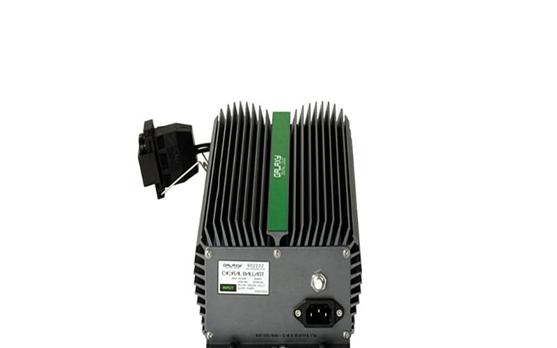
Click to zoom
Application Details
- Equipment Class
- 8CC - Part 18 Consumer Device
- Date of Grant
- Apr 28, 2015
- Application Purpose
- Original Equipment
- Date of Application
- Apr 28, 2015
- Equipment Note
- 902232
- Frequency Range
- 0.04000000 - 0.06000000
- Company
- Sunlight Supply, Inc
- Country
- United States
Documents & Files
Document Text
Text extracted from the exhibit documents filed with the FCC. Open a document above to read the original.
Users Manual
400 / 600 / 1000 Watt + Turbo Charge ® *** READ THESE IMPORTANT INSTRUCTIONS BEFORE USING YOUR BALLAST *** INSTRUCTION MANUAL KEEP ORIGINAL PACKAGING— all returns need to be in the original packaging in order to avoid product damage during shipping. Any damage to products not in their original packaging will not be covered under warranty. SAFETY FIRST! Failure to observe the following safety warnings may result in serious injury. In addition, failure to observe these safety warnings will result in a waiver of all liabilities and will void all warranties. WARNING If the exterior of the lamp is damaged, replace lamp immediately. When re-lamping, make sure lamp has time to cool before touching. Make sure power cord and lamp cord are connected properly. Disconnect power before re-lamping. DO NOT make contact with the interior of the socket while power is on. DO NOT operate light systems in wet locations. DO NOT attempt to rewire or reconfigure your system, it will void warranty and could cause serious safety hazards (i.e. power cord, lamp cord, lamp socket or ballast). DO NOT hang by power or lamp cord. DO NOT plug system into supply voltage other than what is designated on ballast. Keep away from children. DO NOT alter or modify this unit in any way. It may cause bodily injury or death as this is a high power electrical device. DO NOT submerse in water or splash water on the unit. DO NOT plug or unplug the lamp cord while the ballast is energized. These high performance Electronic Ballasts are extremely efficient. They have a high power factor and high luminous efficacy. It’s stable performance creates constant power output even when power fluctuates (power surge). Short circuit protection technology prevents damage to the lamp and other ballasts connected to the same circuit. 1. INSTALLATION PROCEDURE DO NOT alter or modify the electronic ballast in any way. Not only may it damage the unit, it will void the warranty. Lamp power rating must match electronic ballast power rating. OUTPUT TO HPS/MH LAMP Connect lamp cord with male plug to dual universal female lamp cord receptacle on ballast WARRANTY This unit, when properly used will provide you with years of service. It is covered under a 3 year warranty. This warranty will be voided if the unit is misused, abused or altered. Warranty repair or replacement will be at the sole discretion of the manufacturer. Defective units need to be returned to the place of purchase with proof of purchase/receipt. This warranty is expressly in lieu of all other warranties, expressed or implied, including the warranties of merchantability and fitness for use and of all other obligations or liabilities on the part of the seller. This warranty shall not apply to this product or any part thereof which has been damaged by accident, abuse, misuse, modification, negligence, alteration or misapplication. Manufacturer makes no warranty whatsoever in respect to accessories or parts not supplied by manufacturer. This warranty does not cover labor, materials, equipment, etc. to install or de-install lighting fixtures or any other product. Buyers sole and exclusive remedy shall be the repair or replacement of the defective product at the sellers sole discretion. This warranty shall apply only to the United States, including Alaska, Hawaii and territories of the United States and Canada. RETURNING UNITS Please contact your retail store for returns. CONNECT APPROPRIATE AC POWER PLUG HERE AC input 120 (included) or 240V (purchase separately) The Galaxy Digital Logic offers our exclusive Smart Volt ® feature, allowing operation on either 120 or 240 volt power by simply plugging in the appropriate power cord. There is no further modification necessary. It comes with a 120 volt power cord. To run this ballast on 240 volt, purchase the 240 volt power cord separately (part #903082 six foot or #903084 twenty foot). 2. SPECIFICATIONS 120-240 Volts Power source frequency: 50/60Hz Power Factor (cosø): > 0.99 Ambient Temp: 50 ̊F to 120 ̊F Crest Factor: < 1.5 Acoustic Resonance: none Total Harmonic Distortion: (THD): < 10.0% www.galaxyballasts.com Part 18 complianceThis device complies with Part 18 of the FCC Rules. Advisory statement This product may cause interference to radio equipment and should not be installed near maritime safety communications equipment or other critical navigation or communication equipment operating between 0.45-30 MHz. The interference potential of the device or system The interference potential of the device or system is the operating frequency; 60 kHz. Maintenance of the systemUnplug the unit, wait 30 seconds, and plug the unit back in. Simple measures that can be taken by the user to correct interference Move the unit away from any radio device. This product contains delicate electronic components. This means that if it is placed near an object that transmits radio signals, it could cause interference. This could be, for example, mobile telephones, walkie talkies, CB radios, remote controls and microwaves. If interference occurs, move such objects away from the appliance. Do not use the fixture when either its lamp or its power cord are damaged. Replace the power cord only with original certified cords. Replace the lamp only with lamps specified by Gavita (see paragraph 10.1). Modifications to the cords can lead to unwanted electromagnetic effects, which makes the product not comply with legal requirements. 3. NOTES Galaxy Electronic Ballasts will operate with Metal Halide lamps and High Pressure Sodium lamps that are rated at the proper wattage. This unit offers short-circuit and power fluctuation. MAINTENANCE Regularly check the ballast for dust or dirt buildup. Clean the outside of the fixture using a dry or damp cloth. Regularly check the wiring of the product to ensure it is undamaged. 240V WIRING - VERY IMPORTANT! All digital ballasts may malfunction if the 240V circuit has a neutral. The input…
Text truncated - open the document above for the full version.
Cover Letter(s)
FCC Compliance Opinion 2015-1-14 SUPR0149 Information about the Applicant Grantee (Company Name) Sunlight Supply, Inc. FCC Contact Person Bruce LeBlanc Address 5408 NE 88 th St. Bldg A City, State, Zip Vancouver, WA 98665 Job Number SNSY0030 Model 902232 FCC ID 2AEHV902232 Agent NA Approval Type Original Equipment Class 8CC Rule Part 18 Overview This application is for Sunlight Supply’s consumer RF lighting device, FCC ID: 2AEHV902232. Confidentiality requested for allowed files. Request is properly addressed and referenced. Recommendation All items have been resolved and completed to my satisfaction; therefore I recommend this application for approval. Signature Greg Kiemel, TCB Committee 4/27/2015
Cover Letter(s)
Sunlight Supply, Inc Page 1 Cover Letter for FCC Application FCC ID: 2AEHV902232 Date: 04/01/2015 Sunlight Supply requests certification under FCC Part 18 for our consumer RF lighting device with FCC ID number 2AEHV902232. This contains the 120/240V Model 902232. These are all listed under Class B Residential requirements. The radio frequency for each model is identical and was tested under all the same requirements. It utilized a 1000W High Pressure Sodium Lamp in a Single Ended Reflector with a 15 foot lamp cord. Sincerely, Bruce LeBlanc Compliance Manager
Cover Letter(s)
Confidentiality Letter-FCC Date: 4/01/2015 Federal Communications Commission Authorization and Evaluation Division 7435 Oakland Mills Road Columbia, Maryland 21046 To whom it may concern, We hereby respectfully request that under the provision of 47 CFR 0.459 and 0.457(d) the documents listed below and attached with this application for certification be provided with confidential status. Schematics.pdf Operational Description.pdf Frequency Block Diagrams.pdf Internal Photos o Long term Confidentiality due to the circuit board is covered in epoxy and not accessible by the users. Any exhibit / information for which we have requested confidentiality, but which may not be accorded such treatment by the FCC, should be returned to us. The documents listed above contain trade secrets that are treated as confidential by us. Substantial competitive harm to us could result should they be made available to the public. Sincerely, Bruce LeBlanc Compliance Manager
Test Report
Sunlight Supply, Inc. 902232 Digital Ballast FCC 18.305:2014 FCC 18.307:2014 Report #: SNSY0011 Report Prepared By Northwest EMC Inc. NORTHWEST EMC – (888) 364-2378 – www.nwemc.com California – Minnesota – Oregon – New York – Washington WTD 12.5.23 CERTIFICATE OF TEST Last Date of Test: August 06, 2014 Sunlight Supply, Inc. Model: 902232 Digital Ballast Emissions Test Description Specification Test Method Pass/Fail Radiated Emissions FCC 18.305:2014 Consumer equipment MP-5:1986 Pass Conducted Emissions FCC 18.307:2014 Consumer equipment MP-5:1986 Pass Deviations From Test Standards None Approved By: Kyle Holgate, Operations Manager NVLAP Lab Code: 200630-0 This report must not be used to claim product certification, approval, or endorsement by NVLAP, NIST, or any agency of the federal government of the United States of America. Product compliance is the responsibility of the client, therefore the tests and equipment modes of operation represented in this report were agreed upon by the client, prior to testing. This Report may only be duplicated in its entirety. The results of this test pertain only to the sample(s) tested. The specific description is noted in each of the individual sections of the test report supporting this certificate of test. Report No. SNSY00112/17 REV 2012.08.02 REVISION HISTORY Revision Number Description Date Page Number 00 None Barometric Pressure The recorded barometric pressure has been normalized to sea level. Report No. SNSY00113/17 REV 2014.07.25 ACCREDITATIONS AND AUTHORIZATIONS United States FCC - Designated by the FCC as a Telecommunications Certification Body (TCB). Certification chambers, Open Area Test Sites, and conducted measurement facilities are listed with the FCC. A2LA - Accredited by A2LA to ISO / IEC Guide 65 as a product certifier. This allows Northwest EMC to certify transmitters to FCC and IC specifications. NVLAP - Each laboratory is accredited by NVLAP to ISO 17025 Canada IC - Recognized by Industry Canada as a Certification Body (CB). Certification chambers and Open Area Test Sites are filed with IC. European Union European Commission – Validated by the European Commission as a Conformity Assessment Body (CAB) under the EMC directive and as a Notified Body under the R&TTE Directive. Australia/New Zealand ACMA - Recognized by ACMA as a CAB for the acceptance of test data. Korea KCC / RRA - Recognized by KCC’s RRA as a CAB for the acceptance of test data. Japan VCCI - Associate Member of the VCCI. Conducted and radiated measurement facilities are registered. Taiwan BSMI – Recognized by BSMI as a CAB for the acceptance of test data. NCC - Recognized by NCC as a CAB for the acceptance of test data. Singapore IDA – Recognized by IDA as a CAB for the acceptance of test data. Israel MOC – Recognized by MOC as a CAB for the acceptance of test data. Hong Kong OFTA – Recognized by OFTA as a CAB for the acceptance of test data. Vietnam MIC – Recognized by MIC as a CAB for the acceptance of test data. SCOPE For details on the Scopes of our Accreditations, please visit: http://www.nwemc.com/accreditations/ Report No. SNSY00114/17 REV 2013.12.13 EMISSIONS MEASUREMENTS Measurement Uncertainty When a measurement is made, the result will be different from the true or theoretically correct value. The difference is the result of tolerances in the measurement system that cannot be completely eliminated. To the extent that technology allows us, it has been our aim to minimize this error. Measurement uncertainty is a statistical expression of measurement error qualified by a probability distribution. A measurement uncertainty estimation has been performed for each test per our internal quality document WP 342. The estimation is used to compare the measured result with its "true" or theoretically correct value. The expanded measurement uncertainty (K=2) can be found included as part of the applicable test description page. Our measurement data meets or exceeds the measurement uncertainty requirements of the applicable specification; therefore, the test data can be compared directly to the specification limit to determine compliance. The calculations for estimating measurement uncertainty are based upon ETSI TR 100 028 (or CISPR 16-4-1 as applicable), and are available upon request. Measurement Bandwidths Frequency Range (MHz) Peak Data (kHz) Quasi-Peak Data (kHz) Average Data (kHz) 0.01 - 0.15 1.0 0.2 0.2 0.15 - 30.0 10.0 9.0 9.0 30.0 - 1000 100.0 120.0 120.0 Above 1000 1000.0 N/A 1000.0 Measurements were made using the bandwidths and detectors specified. No video filter was used. Sample Calculations Radiated Emissions: Field Strength Measured Level Antenna Factor Cable Factor Amplifier Gain Distance Adjustment Factor External Attenuation 33.5 = 42.6 + 28.6 + 3.1 - 40.8 + 0.0 + 0.0 Conducted Emissions: Adjusted Level Measured Level Transducer Factor Cable Factor External Attenuation 47.1 = 26.7 + 0.3 + 0.1 + 20.0 Report No. SNSY00115/17 REV 2013.06.28 FACILITIES Oregon Labs EV01-12 22975 NW Evergreen Pkwy Hillsboro, OR 97124 (503) 844-4066 California Labs OC01-13 41 Tesla Irvine, CA 92618 (949) 861-8918 New York Labs NY01-04 4939 Jordan Rd. Elbridge, NY 13060 (315) 685-0796 Minnesota Labs MN01-08 9349 W Broadway Ave. Brooklyn Park, MN 55445 (763) 425-2281 Washington Labs NC01-0 5,SU02,SU07 19201 120 th Ave. NE Bothell, WA 98011 (425) 984-6600 VCCI A- 0108 A- 0029 A- 0109 A- 0110 Industry Canada 2834D-1, 2834D-2 2834B-1, 2834B-2, 2834B-3 2834E-1 2834F-1 NVLAP NVLAP Lab Code: 200630-0 NVLAP Lab Code: 200676-0 NVLAP Lab Code: 200761-0 NVLAP Lab Code: 200881-0 NVLAP Lab Code: 200629-0 Report No. SNSY00116/17 WTD 12.5.23 PRODUCT DESCRIPTION Client and Equipment Under Test (EUT) Information Company Name: Sunlight Supply, Inc. Address: 5408 NE 88th Street Bldg A101 City, State, Zip: Vancouver, WA 98665 Test Requested By: Ken Garver Model: 902232 Digital Ballast First Date of Test: August 06, 2014 Last Date of Test: August 06, 2014 Receipt Date of Samples: August 06, 2…
Text truncated - open the document above for the full version.
Test Setup Photos
WTD.2013.12.04, PSA-ESCI 2014.06.19, EmiR5 2014.07.09 RADIATED EMISSIONS WTD.2013.12.04, PSA-ESCI 2014.06.19, EmiR5 2014.07.09 RADIATED EMISSIONS WTD.2013.12.04, PSA-ESCI 2014.06.19, EmiR5 2014.07.09 CONDUCTED EMISSIONS TEST DESCRIPTION Using the mode of operation and configuration noted within this report, conducted emissions tests were performed. The frequency range investigated (scanned), is also noted in this report. Conducted power line measurements are made, unless otherwise specified, over the frequency range from 150 kHz to 30 MHz to determine the line-to-ground radio-noise voltage that is conducted from the EUT power-input terminals that are directly (or indirectly via separate transformer or power supplies) connected to a public power network. Equipment is tested with power cords that are normally used or that have electrical or shielding characteristics that are the same as those cords normally used. Typically those measurements are made using a LISN (Line Impedance Stabilization Network), the 50 measuring port is terminated by a 50 EMI meter or a 50 resistive load. All 50 measuring ports of the LISN are terminated by 50. TEST EQUIPMENT Description Manufacturer Model ID Last Cal. Interval Receiver Rohde & Schwarz ESCI ARH 02/05/2014 12 mo High Pass Filter TTE H97-100K-50-720B HHD 01/22/2014 12 mo EV07 Cables N/A Conducted Cables EVG 03/07/2014 12 mo Attenuator Fairview Microwave SA6B10W-20 RKA 10/24/2013 12 mo LISN Solar 9252-50-R-24-BNC LIR 10/09/2013 12 mo MEASUREMENT UNCERTAINTY Description Expanded k=2 2.94 dB -2.94 dB CONFIGURATIONS INVESTIGATED SNSY0011-1 MODES INVESTIGATED On, 1000 watt setting as requested by client. WTD.2013.12.04, PSA-ESCI 2014.06.19, EmiR5 2014.07.09 CONDUCTED EMISSIONS EUT: 902232 Digital Ballast Work Order: SNSY0011 Serial Number: None Date: 08/06/2014 Customer: Sunlight Supply Inc. Temperature: 25°C Attendees: None Relative Humidity: 45% Customer Project: None Bar. Pressure: 1020 mb Tested By: Carl Engholm Job Site: EV07 Power: 110VAC/60Hz Configuration: SNSY0011-1 TEST SPECIFICATIONS Specification: Consumer equipment Method: FCC 18.307:2014 MP-5:1986 TEST PARAMETERS Run #: 4 Line: Neutral Ext. Attenuation (dB): 20 COMMENTS Testing started after 15 minute warm-up period. EUT OPERATING MODES On, 1000 watt setting as requested by client. DEVIATIONS FROM TEST STANDARD None 0 10 20 30 40 50 60 70 80 90 100 0110100 dBuV MHz Peak Data - vs - Quasi Peak Limit WTD.2013.12.04, PSA-ESCI 2014.06.19, EmiR5 2014.07.09 CONDUCTED EMISSIONS RESULTS - Run #4 Peak Data - vs - Quasi Peak Peak Limit Freq (MHz) Amp. (dBuV) Factor (dB) Adjusted (dBuV) Spec. Limit (dBuV) Margin (dB) 10.810 19.1 19.5 38.6 48.0 -9.4 9.949 18.5 19.5 38.0 48.0 -10.0 10.732 18.2 19.5 37.7 48.0 -10.3 23.323 18.0 19.6 37.6 48.0 -10.4 23.552 17.8 19.6 37.4 48.0 -10.6 23.230 17.8 19.6 37.4 48.0 -10.6 23.138 17.7 19.6 37.3 48.0 -10.7 9.484 17.8 19.5 37.3 48.0 -10.7 10.027 17.8 19.5 37.3 48.0 -10.7 10.374 17.8 19.5 37.3 48.0 -10.7 10.429 17.8 19.5 37.3 48.0 -10.7 10.854 17.8 19.5 37.3 48.0 -10.7 9.798 17.7 19.5 37.2 48.0 -10.8 10.056 17.7 19.5 37.2 48.0 -10.8 10.263 17.7 19.5 37.2 48.0 -10.8 0.454 17.4 19.8 37.2 48.0 -10.8 11.028 17.7 19.5 37.2 48.0 -10.8 10.001 17.6 19.5 37.1 48.0 -10.9 10.330 17.6 19.5 37.1 48.0 -10.9 10.603 17.6 19.5 37.1 48.0 -10.9 10.691 17.6 19.5 37.1 48.0 -10.9 11.002 17.6 19.5 37.1 48.0 -10.9 23.581 17.4 19.7 37.1 48.0 -10.9 23.212 17.4 19.6 37.0 48.0 -11.0 23.086 17.4 19.6 37.0 48.0 -11.0 22.887 17.4 19.6 37.0 48.0 -11.0 CONCLUSION Pass Tested By WTD.2013.12.04, PSA-ESCI 2014.06.19, EmiR5 2014.07.09 CONDUCTED EMISSIONS EUT: 902232 Digital Ballast Work Order: SNSY0011 Serial Number: None Date: 08/06/2014 Customer: Sunlight Supply Inc. Temperature: 25°C Attendees: None Relative Humidity: 45% Customer Project: None Bar. Pressure: 1020 mb Tested By: Carl Engholm Job Site: EV07 Power: 110VAC/60Hz Configuration: SNSY0011-1 TEST SPECIFICATIONS Specification: Consumer equipment Method: FCC 18.307:2014 MP-5:1986 TEST PARAMETERS Run #: 5 Line: High Line Ext. Attenuation (dB): 20 COMMENTS Testing started after 15 minute warm-up period. EUT OPERATING MODES On, 1000 watt setting as requested by client. DEVIATIONS FROM TEST STANDARD None 0 10 20 30 40 50 60 70 80 90 100 0110100 dBuV MHz Peak Data - vs - Quasi Peak Limit WTD.2013.12.04, PSA-ESCI 2014.06.19, EmiR5 2014.07.09 CONDUCTED EMISSIONS RESULTS - Run #5 Peak Data - vs -Quasi Peak Limit Freq (MHz) Amp. (dBuV) Factor (dB) Adjusted (dBuV) Spec. Limit (dBuV) Margin (dB) 11.456 20.8 19.5 40.3 48.0 -7.7 10.880 20.5 19.5 40.0 48.0 -8.0 11.087 20.5 19.5 40.0 48.0 -8.0 11.271 20.4 19.5 39.9 48.0 -8.1 10.496 20.2 19.5 39.7 48.0 -8.3 10.529 19.9 19.5 39.4 48.0 -8.6 11.194 19.9 19.5 39.4 48.0 -8.6 12.501 19.9 19.5 39.4 48.0 -8.6 12.265 19.6 19.5 39.1 48.0 -8.9 10.932 19.5 19.5 39.0 48.0 -9.0 10.957 19.5 19.5 39.0 48.0 -9.0 11.375 19.4 19.5 38.9 48.0 -9.1 11.958 19.4 19.5 38.9 48.0 -9.1 10.784 19.3 19.5 38.8 48.0 -9.2 10.551 19.2 19.5 38.7 48.0 -9.3 10.747 19.2 19.5 38.7 48.0 -9.3 12.793 19.2 19.5 38.7 48.0 -9.3 12.409 19.2 19.5 38.7 48.0 -9.3 9.661 19.1 19.5 38.6 48.0 -9.4 11.408 19.1 19.5 38.6 48.0 -9.4 11.545 19.1 19.5 38.6 48.0 -9.4 12.036 19.1 19.5 38.6 48.0 -9.4 11.334 19.0 19.5 38.5 48.0 -9.5 11.441 19.0 19.5 38.5 48.0 -9.5 12.394 19.0 19.5 38.5 48.0 -9.5 11.740 19.0 19.5 38.5 48.0 -9.5 CONCLUSION Pass Tested By
Contact Information
Applicant
Bruce LeBlanc(Compliance Manager)
Test Firm
Northwest EMC, Inc.Greg Kiemel
Technical Specifications
| # | Rule Parts | Frequency Range | Power Output |
|---|---|---|---|
| 1 | 18 | 0.04 MHz - 0.06 MHz | - |
Other Applications from Sunlight Supply, Inc
2AEHV902238
Nov 16, 2015902238
Equipment Class
8CC - Part 18 Consumer Device
2AEHV902235
May 31, 2015902235
Equipment Class
8CC - Part 18 Consumer Device
2AEHV902215
May 31, 2015902215
Equipment Class
8CC - Part 18 Consumer Device
2AEHV902220
May 31, 2015902220
Equipment Class
8CC - Part 18 Consumer Device
2AEHV902518
May 31, 2015902518
Equipment Class
8CC - Part 18 Consumer Device