2AEMI-P2Wi-Fi Module
Particle Industries, Inc.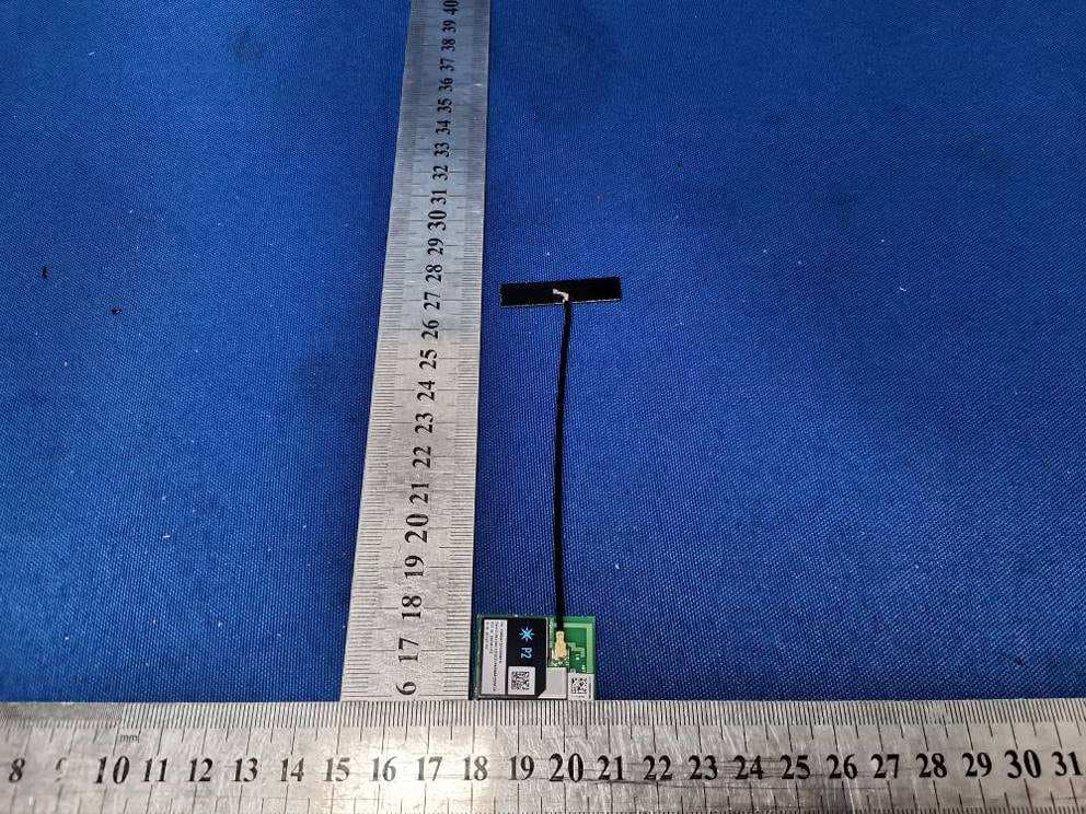
Click to zoom
Application Details
- Equipment Class
- NII - Unlicensed National Information Infrastructure TX
- Date of Grant
- Jun 08, 2022
- Application Purpose
- Original Equipment
- Date of Application
- Jun 08, 2022
- Equipment Note
- Wi-Fi Module
- Frequency Range
- 5745.00000000 - 5825.00000000
- Company
- Particle Industries, Inc.
- Country
- United States
Documents & Files
Document Text
Text extracted from the exhibit documents filed with the FCC. Open a document above to read the original.
Users Manual
P2 Datasheet Functional description The P2 is a SMD module with a microcontroller and Wi-Fi networking. The form-factor is the same as the P1, but the P2 supports 2.4 GHz and 5 GHz Wi-Fi, BLE, and has much larger RAM and flash that can support larger applications. 802.11a/b/g/n Wi-Fi, 2.4 GHz and 5 GHz Integrated PCB antenna Integrated U.FL connector for external antenna Integrated RF switch BLE 5 using same antenna as Wi-Fi Realtek RTL8721DM MCU ARM Cortex M23 CPU, 200 MHz 2048 KB (2 MB) user application maximum size 2 MB flash file system FCC, IC, and CE certified OVERVIEW FEATURES Interfaces The P2 includes an on-module PCB trace antenna and a U.FL connector that allows the user to connect an external antenna. The antenna is selected in software. The default is the PCB trace antenna. The area surrounding the PCB antenna on the carrier PCB should be free of ground planes and signal traces for maximum Wi-Fi performance when using the trace antenna. Device operation in the 5150-5250 MHz band is only for indoor use to reduce the potential for harmful interference to co-channel mobile satellite systems. Antenna TypeManufacturerMFG. Part #Gain External antennaWistron NeWeb Corporation95XEAK15.G531.55dBi Internal PCB AntennaIncluded-2.41dBi BLOCK DIAGRAM RF FCC APPROVED ANTENNAS The P2 module supports programming and debugging use SWD (Serial Wire Debug) on pins D6 and D7. PinJTAGMCU PinP2 Pin #Pull at boot D7SWDIOPA[27]54Pull-up D6SWCLKPB[3]55Pull-down 3V3Power GNDGround RSTReset When the bootloader starts, for a brief period of time a weak pull-up is applied to pin D7 and pull- down to pin D6 to detect whether a SWD debugger is attached. After boot, you can use these pins for regular GPIO, but beware of a possible GPIO state change caused by the pull-up or pull-down when using these pins as output. Note that SWD is shared with GPIO pins D6 and D7, and by default SWD is only enabled while the bootloader is running, immediately at boot, and when in DFU mode (blinking yellow). Only Debug builds in Particle Workbench have SWD enabled in when user firmware is running. SWD/JTAG Memory Map [This information is from the P1, and is likely to remain the same, but is subject to change.] The DCT area of flash memory has been mapped to a separate DFU media device so that we can incrementally update the application data. This allows one item (say, server public key) to be updated without erasing the other items. DCT layout in release/stable found here in firmware. RegionOffsetSize system flags032 version322 device private key341216 device public key1250384 ip config1634120 feature flags17544 country code17584 claim code176263 claimed18251 ssid prefix182626 device code18526 version string185832 dns resolve1890128 reserved1201864 server public key2082768 padding28502 flash modules2852100 product store295224 antenna selection29761 cloud transport29771 alt device public key2978128 alt device private key3106192 alt server public key3298192 alt server address3490128 device id361812 radio flags36301 mode button mirror363132 led mirror366396 led theme375964 reserved23823435 Note: Writing 0xFF to offset 34 (DEFAULT) or 3106 (ALTERNATE) will cause the device to re- generate a new private key on the next boot. Alternate keys are currently unsupported on the P1 but are used on the Electron as UDP/ECC keys. You should not need to use this feature unless your keys are corrupted. DCT LAYOUT // Regenerate Default Keys echo -en "\xFF" > fillbyte && dfu-util -d 2b04:d00a -a 1 -s 34 -D fillbyte // Regenerate Alternate Keys echo -en "\xFF" > fillbyte && dfu-util -d 2b04:d00a -a 1 -s 3106 -D fillbyte Pin and button definition Peripheral TypeQtyInput(I) / Output(O) Digital22I/O Analog (ADC)6I SPI2I/O I2C1I/O UART3I/O USB1I/O PWM6O Pin NameModule PinMCU A0 / D1150ADC_4 PB[1] A1 / D1243ADC_5 PB[2] A2 / D1349ADC_3 PB[7] A5 / D1423ADC_0 PB[4] D0 / A336ADC_2Wire (SDA) PB[6] D1 / A435ADC_1Wire (SCL) PB[5] D10 / WKP30 Serial3 (CTS)PA[15] D245 SPI1 (MOSI)Serial2 (RTS)PA[16] D351 SPI1 (MISO)Serial2 (CTS)PA[17] D452 SPI1 (SCK)Serial2 (TX)PA[18] D553 SPI1 (SS)Serial2 (RX)PA[19] D655 SWCLK PB[3] D754 SWDIO PA[27] NC7 PIN MARKINGS GPIO AND PORT LISTING RGBB31 PB[22] RGBG32 PB[23] RGBR29 PA[30] RX / D963 Serial1 (RX)PA[8] S0 / D1540 SPI (MOSI)Serial3 (TX)PA[12] S1 / D1641 SPI (MISO)Serial3 (RX)PA[13] S2 / D1742 SPI (SCK)Serial3 (RTS)PA[14] S3 / D1844 SPI (SS) PB[26] S4 / D1947 PA[0] S5 / D2048 PB[29] S6 / D2133 PB[31] TX / D864 Serial1 (TX)PA[7] USBDATA-62 PA[25] USBDATA+61 PA[26] The P2 supports six ADC inputs. PinPin NameDescriptionInterfaceMCU 23A5 / D14A5 Analog in, GPIO, PWM.ADC_0PB[4] 35D1 / A4D1 GPIO, PWM, I2C SCL, A4 Analog InADC_1PB[5] 36D0 / A3D0 GPIO, PWM, I2C SDA, A3 Analog InADC_2PB[6] 43A1 / D12A1 Analog in, GPIOADC_5PB[2] 49A2 / D13A2 Analog in, PWM, GPIOADC_3PB[7] 50A0 / D11A0 Analog in, GPIOADC_4PB[1] ADC inputs are single-ended and limited to 0 to 3.3V Resolution is 12 bits The P2 supports three UART serial interfaces. PinPin NameDescriptionInterfaceMCU 30D10 / WKPD10 GPIO, Serial 3 CTS. (Was WKP/A7 on P1.)Serial3 (CTS)PA[15] 40S0 / D15S0 GPIO, PWM, SPI MOSI, Serial3 TX. (Was P1S0 on P1.)Serial3 (TX)PA[12] 41S1 / D16S1 GPIO, PWM, SPI MISO, Serial3 RX. (Was P1S1 on P1.)Serial3 (RX)PA[13] 42S2 / D17S2 GPIO, SPI SCK, Serial3 RTS. (Was P1S2 on P1.)Serial3 (RTS)PA[14] 45D2D2 GPIO, Serial2 RTS, SPI1 MOSISerial2 (RTS)PA[16] 51D3D3 GPIO, Serial2 CTS, SPI1 MISOSerial2 (CTS)PA[17] 52D4D4 GPIO, Serial2 TX, SPI1 SCKSerial2 (TX)PA[18] 53D5D5 GPIO, Serial2 RX, SPI1 SSSerial2 (RX)PA[19] 63RX / D9Serial1 RX (received data), GPIOSerial1 (RX)PA[8] 64TX / D8Serial1 TX (transmitted data), GPIOSerial1 (TX)PA[7] The UART pins are 3.3V and must not be connected directly to a RS-232C port or to a 5V TTL serial port ADC (ANALOG TO DIGITAL CONVERTER) UART SERIAL Hardware flow control is optional; if not used then the RTS and CTS pins can be used as regular GPIO Serial1 uses the RTL872x UART_LOG peripheral Serial2 uses the RTL872x HS_UART0 periphe…
Text truncated - open the document above for the full version.
Cover Letter(s)
SCS-F026 Modular Approval Letter P1ge 1 NUMPAGES |2} 775 Montague Expressway Milpitas, CA 95035 Tel: 408-526-1188 Fax: 408-526-1088 Email: [email protected] Website: https://www.cps.bureauveritas.com/ Modular Approval Declaration Letter Reason for Amendment (current / obsolete) Revision History Approved Date From To Initial Release (Obsolete) 1.0 1.0 Dec-04-2006 Added IC Modular Letter (Obsolete) 1.0 2.0 Feb 16 2009 Add LMA and MA option (Obsolete) 2.0 3.0 April 14 2010 Revised per RSS Gen issue 3.0 (Obsolete) 3.0 4.0 Jan 12 2011 Removed Foot(2) (obsolete) 4.0 5.0 July 19 2011 Adding New note per KDB996369 D01 V01R03 (obsolete) 5.0 6.0 August 29 2011 Updated company template & Added text box (obsolete) 6.0 7.0 Jan-31-2012 Updated modular requirement (obsolete) 7.0 8.0 Sept 05 2014 Updated template to meet RSP 100 issue 10 (obsolete) 8.0 9.0 Nov 20 2014 Updated template to meet RSP 100 issue 11 (obsolete)) 9.0 10.0 March 19 2015 Revised the Modular Requirement statements (obsolete) 10.0 11.0 July 28, 2016 Updated template with BV logo (current) 11.0 12.0 June 26, 2019 Updated contact info and references 12.0 13.0 Aug-30-2020 SCS-F026 Modular Approval Letter P2ge 2 NUMPAGES |2} Particle Industries,Inc 2022/04/20 (Product name) FCC ID: 2AEMI-BRN402 , is seeking FCC Authorization as a Single Modular Transmitter / Single Limited Modular Transmitter (Please check one) The EUT meets the requirements for Single Modular Approval / Single Limited Modular Approval (Please check one) as detailed in KDB 996369. Compliance to each of the requirements is described below: Item Modular requirement Yes No Please provide a detailed explanation if the answer is “No.” 1 Have its own RF shielding √ 2 Have buffered modulation/data inputs (if such inputs are provided) √ 3 The modular transmitter must have its own power supply regulation. √ 4 Meet the antenna requirements of section 15.203 √ 5 Be tested in a stand-alone configuration, i.e., the antenna, AC or DC power and data input/output lines must be connected to the module but, the module must not be inside another case during testing. √ 6 Be labeled with its own FCC ID number, and if the FCC ID is not visible when the module is installed inside another device, then the outside of the device into which the module is installed must also display a label referring to the enclosed module. √ 7 The modular transmitter is manufactured so that the user can not influence the operation of the transmitter that will operate outside of the scope of the regulations. √ 8 Address compliance with the Commission`s RF exposure limits in Sections 1.1310 and 2.1093. √ Note: (1) LMA may be granted when one or more of the requirements in the table above cannot be demonstrated. LMA will also be issued in those instances where applicants can demonstrate that they will retain control over the final installation of the device, such that compliance of the end product is assured. In such cases, an operating condition on the LMA for the module must state that the module is only approved for use when installed in devices produced by a specific manufacturer. When LMA is sought, the application for equipment certification must specifically state how control of the end product into which the module will be installed, and will be maintained, such that full compliance of the end product is always ensured. (2) Please provide Clear and specific instructions describing the conditions, limitations and procedures for third-parties to use and/or integrate the module into a host device. (3) For non-Software Defined Radio transmitter modules where software is used to ensure compliance of the device, technical description of how such control is implemented to ensure prevention of third party modification must be provided (see KDB 594280). Note 1: Compliance of a module in its final configuration is the responsibility of the applicant. A host device will not be considered certified if the instructions regarding antenna configuration provided in the original description, of one or more separately certified modules it contains, were not followed. Example: A separately certified low-power transceiver module using Bluetooth technology which is housed in a desktop computer, laptop or peripheral does not require the overall system to be recertified, if the desktop computer, laptop or peripheral, as a stand-alone unit, complies with all applicable technical standards. SCS-F026 Modular Approval Letter P3ge 3 NUMPAGES |2} Client’s signature Client’s name / title Zach Supalla CEO Contact information / address 126 Post St, 4th floor, San Francisco, CA 94108 USA
Cover Letter(s)
SCS-F019: Confidentiality Request Letter Page 1 of 2 Rev 7.0 775 Montague Expressway Milpitas, CA 95035 Tel: 408-526-1188 Fax: 408-526-1088 Email: [email protected] Website: https://www.cps.bureauveritas.com/ Confidentiality Request Letter Reason for Amendment (current / obsolete) Revision History Approved Date From To Initial Release (obsolete) 1.0 1.0 Nov-14-2006 Adding CFR 2.459 (obsolete) 1.0 2.0 August – 11 - 2008 Updated company template & Added text box (obsolete) 2.0 3.0 Jan-31-2012 Added IC confidentiality letter form (obsolete) 3.0 4.0 March-26-2015 Corrections to STC form. Added reference to KDB (obsolete) 4.0 5.0 Nov-19-2015 Updated company logo (current) 5.0 6.0 Jun-26-2019 Updated References and Contact Info 6.0 7.0 Aug-30-2020 SCS-F019: Confidentiality Request Letter Page 2 of 2 Rev 7.0 Particle Industries,Inc 2022/04/20 To: Federal Communications Commission Authorization and Evaluation Division 7435 Oakland Mills Road Columbia, MD 21046-1609 Cc: Bureau Veritas Consumer Products Services Inc. 775 Montague Expressway Milpitas, CA 95035 Subject: Confidentiality Request for FCC ID: 2AEMI-P2 Pursuant to CFR 47 sections 0.457 and 0.459, we respectfully request permanent confidential treatment of the following Exhibits accompanying this application be held confidential: Type of Confidentiality Requested Exhibit Short Term Permanent Block Diagram Short Term External Photos Short Term Permanent i Internal Photos Short Term Permanent Operational Description/ Theory of Operation Short Term Permanent Parts List Short Term Permanent Tune-Up Procedure Short Term Permanent Schematics Short Term Test Setup Photos Short Term Permanent i User’s Manual Short Term Permanent SOFTWARE SECURITY REQUIREMENTS FOR U-NII DEVICES for 5GHz The above materials contain trade secrets and proprietary information not customarily released to the public. The public disclosure of these materials may be harmful to the applicant and provide unjustified benefits to its competitors. Permanent Confidentiality: The applicant requests the exhibits listed above as permanently confidential be permanently withheld from public review due to materials that contain trade secrets and proprietary information not customarily released to the public. Short-Term Confidentiality: To avoid premature release of sensitive information prior to marketing or release of the product to the public, the applicant requests the following documents contained in this certification application be temporarily withheld from public disclosure for an initial period of 45 or 180 days; or for a specified date of not to exceed 180 days from the Grant Date The applicant understands that disclosure of this application and all accompanying documentation will not be made before the date of the Grant for this application. Sincerely, Client’s signature: Client’s name & title: Zach Supalla /CEO Contact information / address: 325 9th Street, San Francisco, CA 94103 United States i Permanent confidentiality may be requested in accordance with FCC KDB 726920
External Photos
Bureau Veritas Shenzhen Co., Ltd. Dongguan Branch No. 96, Guantai Road (Houjie Section), Houjie Town, Dongguan City, Guangdong Province. 523942. People’s Republic of China. Tel.: +86 769 8998 2098 Fax: +86 769 8593 1080 Email: [email protected] Page 1 of 3 Report Version A Reference No.: 2202WDG0092-1 PHOTOGRAPHS OF THE EUT External PCB ANT Bureau Veritas Shenzhen Co., Ltd. Dongguan Branch No. 96, Guantai Road (Houjie Section), Houjie Town, Dongguan City, Guangdong Province. 523942. People’s Republic of China. Tel.: +86 769 8998 2098 Fax: +86 769 8593 1080 Email: [email protected] Page 2 of 3 Report Version A Reference No.: 2202WDG0092-1 PCB ANT Bureau Veritas Shenzhen Co., Ltd. Dongguan Branch No. 96, Guantai Road (Houjie Section), Houjie Town, Dongguan City, Guangdong Province. 523942. People’s Republic of China. Tel.: +86 769 8998 2098 Fax: +86 769 8593 1080 Email: [email protected] Page 3 of 3 Report Version A Reference No.: 2202WDG0092-1
ID Label/Location Info
*17.98 C=2.0 *15.37 REEL DIRECTION BNEW RELEASE SANDY CHEN WNC CONFIDENTIAL 4L.DHSKP.001 B 2 YOLANDA CHENG YOLANDA CHENG SANDY CHEN 11/23/21 11/23/21 11/23/21 11/23/21 LABEL,P2,SHIELDING COVER LBL,HIGH TEMP,DHSK-PC1 1/1 1 OF 1 20 Park Avenue II, Hsinchu Science Park, Hsinchu 308, Taiwan, R.O.C. Tel: 886-3-6667799 Fax: 886-3-5788726 TEST I TEMTEST SPECTEST CONDITIONCRITERIA 1 附著力測 試 ISO Class.: 1 ASTM Class.: 4 B ASTM D3359-02/ ISO 2409:2007 Det achment of smal l fl akes of the coat ing at the inter sections of the cuts. A cross-cut ar ea not signifi cantly greater than 5 % is affected. *1 *2 DIE CUT ON LINE PRINT NOTES: 1. MATERIAL: WHITE PI (#25DP-1025W), t=0.043 2. ADHESIVE: , t=0.023 2. TEMPERATURE RESISTANT= 280°C x 10min/ 320°C x 10s 3. COLOR: a) BACKGROUND= PANTONE 289 C b) PARTICLE LOGO & P2= PANTONE PROCESS CYAN C 4. : SHIELDING COVER 5. 6. 3±0.5mm, 3±0.5mm 7. :30mm±0.3mm,120~315mm±0.5mm,315±0.8mm 8. TEST REQUIREMENTS: PMS 289 CPMS PROCESS CYAN C SN: P046AF14800010C DevID: 0a10aced202194944a00010c FCC ID: 2AEMI-P2 IC: 20127-P2
Internal Photos
Bureau Veritas Shenzhen Co., Ltd. Dongguan Branch No. 96, Guantai Road (Houjie Section), Houjie Town, Dongguan City, Guangdong Province. 523942. People’s Republic of China. Tel.: +86 769 8998 2098 Fax: +86 769 8593 1080 Email: [email protected] Page 1 of 1 Report Version A Reference No.: 2202WDG0092-1 PHOTOGRAPHS OF THE EUT
RF Exposure Info
Bureau Veritas Shenzhen Co., Ltd. Dongguan Branch No. 96, Guantai Road (Houjie Section), Houjie Town, Dongguan City, Guangdong Province. 523942. People’s Republic of China. Tel: +86 769 8998 2098 Fax: +86 769 8593 1080 Email: [email protected] Page 1 of 8 Report Version A Test Report No.: FM2202WDG0092 RF EXPOSURE REPORT Applicant Particle Industries,Inc Address 325 9th Street, San Francisco, CA 94103 United States Manufacturer or Supplier Particle Industries,Inc Address 325 9th Street, San Francisco, CA 94103 United States Product Wi-Fi Module Brand Name Particle Model P2 Additional Model & Model Difference N/A Date of tests Feb. 21, 2021 ~ Apr. 11, 2022 FCC Part 2 (Section 2.1091) KDB 447498 D01 IEEE C95.1 CONCLUSION: The submitted sample was found to COMPLY with the test requirement Tested by Lucas Chen Project Engineer / EMC Department Approved by Glyn He Assistant Manager / EMC Department Date: May 19, 2022 This report is governed by, and incorporates by reference, CPS Conditions of Service as posted at the date of issuance of this report at https://www.cps.bureauveritas.com/terms-conditions and is intended for your exclusive use. Any copying or replication of this report to or for any other person or entity, or use of our name or trademark, is permitted only with our prior written permission. This report sets forth our findings solely with respect to the test samples identified herein. The results set forth in this report are not indicative or representative of the quality or characteristics of the lot from which a test sample was taken or any similar or identical product unless specifically and expressly noted. Our report includes all of the tests requested by you and the results thereof based upon the information that you provided to us. Measurement uncertainty is only provided upon request for accredited tests. You have 60 days from date of issuance of this report to notify us of any material error or omission caused by our negligence or if you require measurement uncertainty; provided, however, that such notice shall be in writing and shall specifically address the issue you wish to raise. A failure to raise such issue within the prescribed time shall constitute you unqualified acceptance of the completeness of this report, the tests conducted and the correctness of the report contents. Bureau Veritas Shenzhen Co., Ltd. Dongguan Branch No. 96, Guantai Road (Houjie Section), Houjie Town, Dongguan City, Guangdong Province. 523942. People’s Republic of China. Tel: +86 769 8998 2098 Fax: +86 769 8593 1080 Email: [email protected] Page 2 of 8 Report Version A Test Report No.: FM2202WDG0092 TABLE OF CONTENTS RELEASE CONTROL RECORD ................................................................................ 3 1. CERTIFICATION .............................................................................................. 4 2. RF EXPOSURE LIMIT ..................................................................................... 5 3. MPE CALCULATION FORMULA ..................................................................... 5 4. CLASSIFICATION ........................................................................................... 5 5. ANTENNA GAIN .............................................................................................. 6 6. CALCULATION RESULT OF MAXIMUM CONDUCTED POWER ................... 7 Bureau Veritas Shenzhen Co., Ltd. Dongguan Branch No. 96, Guantai Road (Houjie Section), Houjie Town, Dongguan City, Guangdong Province. 523942. People’s Republic of China. Tel: +86 769 8998 2098 Fax: +86 769 8593 1080 Email: [email protected] Page 3 of 8 Report Version A Test Report No.: FM2202WDG0092 RELEASE CONTROL RECORD ISSUE NO. REASON FOR CHANGE DATE ISSUED FM2202WDG0092 Original release May 19, 2022 Bureau Veritas Shenzhen Co., Ltd. Dongguan Branch No. 96, Guantai Road (Houjie Section), Houjie Town, Dongguan City, Guangdong Province. 523942. People’s Republic of China. Tel: +86 769 8998 2098 Fax: +86 769 8593 1080 Email: [email protected] Page 4 of 8 Report Version A Test Report No.: FM2202WDG0092 1. CERTIFICATION PRODUCT: Wi-Fi Module BRAND NAME: Particle MODEL NO.: P2 ADDITIONAL MODEL: N/A FCC ID: 2AEMI-P2 TEST SAMPLE: ENGINEERING SAMPLE APPLICANT: Particle Industries,Inc STANDARDS: FCC Part 2 (Section 2.1091) KDB 447498 D01 IEEE C95.1 Bureau Veritas Shenzhen Co., Ltd. Dongguan Branch No. 96, Guantai Road (Houjie Section), Houjie Town, Dongguan City, Guangdong Province. 523942. People’s Republic of China. Tel: +86 769 8998 2098 Fax: +86 769 8593 1080 Email: [email protected] Page 5 of 8 Report Version A Test Report No.: FM2202WDG0092 2. RF EXPOSURE LIMIT LIMITS FOR MAXIMUM PERMISSIBLE EXPOSURE (MPE) FREQUENCY RANGE (MHz) ELECTRIC FIELD STRENGTH (V/m) MAGNETIC FIELD STRENGTH (A/m) POWER DENSITY (mW/cm 2 ) AVERAGE TIME (minutes) LIMITS FOR GENERAL POPULATION / UNCONTROLLED EXPOSURE 300-1500 ... ... F/1500 30 1500-100,000 ... ... 1.0 30 F = Frequency in MHz 3. MPE CALCULATION FORMULA Pd = (Pout*G) / (4*pi*r 2 ) where Pd = power density in mW/cm 2 Pout = output power to antenna in mW G = gain of antenna in linear scale Pi = 3.1416 R = distance between observation point and center of the radiator in cm 4. CLASSIFICATION The antenna of this product, under normal use condition, is at least 20cm away from the body of the user. So, this device is classified as Mobile Device. Bureau Veritas Shenzhen Co., Ltd. Dongguan Branch No. 96, Guantai Road (Houjie Section), Houjie Town, Dongguan City, Guangdong Province. 523942. People’s Republic of China. Tel: +86 769 8998 2098 Fax: +86 769 8593 1080 Email: [email protected] Page 6 of 8 Report Version A Test Report No.: FM2202WDG0092 5. ANTENNA GAIN The antennas provided to the EUT, please refer to the following table: Frequency Band Antenna Gain (dBi) Antenna Type BT 2.4GHz 2.41 PCB Antenna Wi-Fi 2.4GHz 2.41 PCB Ante…
Text truncated - open the document above for the full version.
Test Report
Bureau Veritas Shenzhen Co., Ltd. Dongguan Branch No. 96, Guantai Road (Houjie Section), Houjie Town, Dongguan City, Guangdong Province. 523942. People’s Republic of China. Tel: +86 769 8998 2098 Fax: +86 769 8593 1080 Email: [email protected] Page 1 of 109 Report Version A Test Report No.: RF2202WDG0092-3 TEST REPORT Applicant Particle Industries,Inc Address 325 9th Street, San Francisco, CA 94103 United States Manufacturer or Supplier Particle Industries,Inc Address 325 9th Street, San Francisco, CA 94103 United States Product Name Wi-Fi Module Brand Name Particle Model P2 Additional Model & Model Difference N/A Date of tests Feb. 21, 2021 ~ Apr. 11, 2022 The tests have been carried out according to the requirements of the following standard: FCC Part 15, Subpart E, Section 15.407 CONCLUSION: The submitted sample was found to COMPLY with the test requirement Tested by Lucas Chen Project Engineer / EMC Department Approved by Glyn He Assistant Manager / EMC Department Date: May 19, 2022 This report is governed by, and incorporates by reference, CPS Conditions of Service as posted at the date of issuance of this report at https://www.cps.bureauveritas.com/terms-conditions and is intended for your exclusive use. Any copying or replication of this report to or for any other person or entity, or use of our name or trademark, is permitted only with our prior written permission. This report sets forth our findings solely with respect to the test samples identified herein. The results set forth in this report are not indicative or representative of the quality or characteristics of the lot from which a test sample was taken or any similar or identical product unless specifically and expressly noted. Our report includes all of the tests requested by you and the results thereof based upon the information that you provided to us. Measurement uncertainty is only provided upon request for accredited tests. You have 60 days from date of issuance of this report to notify us of any material error or omission caused by our negligence or if you require measurement uncertainty; provided, however, that such notice shall be in writing and shall specifically address the issue you wish to raise. A failure to raise such issue within the prescribed time shall constitute you unqualified acceptance of the completeness of this report, the tests conducted and the correctness of the report contents. Bureau Veritas Shenzhen Co., Ltd. Dongguan Branch No. 96, Guantai Road (Houjie Section), Houjie Town, Dongguan City, Guangdong Province. 523942. People’s Republic of China. Tel: +86 769 8998 2098 Fax: +86 769 8593 1080 Email: [email protected] Page 2 of 109 Report Version A Test Report No.: RF2202WDG0092-3 TABLE OF CONTENTS RELEASE CONTROL RECORD ............................................................................................................ 4 1. SUMMARY OF TEST RESULTS .................................................................................................... 5 1.1 MEASUREMENT UNCERTAINTY ......................................................................................... 5 2. GENERAL INFORMATION ............................................................................................................ 6 2.1 GENERAL DESCRIPTION OF EUT ........................................................................................... 6 2.2 DESCRIPTION OF TEST MODES ............................................................................................. 7 2.2.1 TEST MODE APPLICABILITY AND TESTED CHANNEL DETAIL ................................... 10 2.3 DUTY CYCLE OF TEST SIGNAL ............................................................................................ 12 2.4 DESCRIPTION OF SUPPORT UNITS ..................................................................................... 13 2.5 GENERAL DESCRIPTION OF APPLIED STANDARDS .......................................................... 13 3. TEST TYPES AND RESULTS ...................................................................................................... 14 3.1 RADIATED EMISSION AND BANDEDGE MEASUREMENT .................................................. 14 3.1.1 LIMITS OF RADIATED EMISSION AND BANDEDGE MEASUREMENT ....................... 14 3.1.2 LIMITS OF UNWANTED EMISSION OUT OF THE RESTRICTED BANDS .................. 15 3.1.3 TEST INSTRUMENTS ..................................................................................................... 16 3.1.4 TEST PROCEDURES ..................................................................................................... 17 3.1.5 DEVIATION FROM TEST STANDARD ........................................................................... 17 3.1.6 TEST SETUP ................................................................................................................... 18 3.1.7 EUT OPERATING CONDITION ...................................................................................... 19 3.1.8 TEST RESULTS .............................................................................................................. 20 3.2 CONDUCTED EMISSION MEASUREMENT ........................................................................... 75 3.2.1 LIMITS OF CONDUCTED EMISSION MEASUREMENT ............................................... 75 3.2.2 TEST INSTRUMENTS ..................................................................................................... 75 3.2.3 TEST PROCEDURES ..................................................................................................... 76 3.2.4 DEVIATION FROM TEST STANDARD ........................................................................... 76 3.2.5 TEST SETUP ................................................................................................................... 76 3.2.6 EUT OPERATING CONDITIONS .................................................................................... 76 3.2.7 …
Text truncated - open the document above for the full version.
Test Report
Bureau Veritas Shenzhen Co., Ltd. Dongguan Branch No. 96, Guantai Road (Houjie Section), Houjie Town, Dongguan City, Guangdong Province. 523942. People’s Republic of China. Tel: +86 769 8998 2098 Fax: +86 769 8593 1080 Email: [email protected] Page 1 of 22 Report Version A Test Report No.: RF2202WDG0092-4 TEST REPORT Applicant Particle Industries,Inc Address 325 9th Street, San Francisco, CA 94103 United States Manufacturer or Supplier Particle Industries,Inc Address 325 9th Street, San Francisco, CA 94103 United States Product Name Wi-Fi Module Brand Name Particle Model P2 Additional Model & Model Difference N/A FCC ID 2AEMI-P2 Date of tests Feb. 21, 2021 ~ Apr. 11, 2022 The tests have been carried out according to the requirements of the following standard: FCC Part 15, Subpart E, Section 15.407 FCC 06-96 KDB 905462 D02 UNII DFS Compliance Procedures New Rules v02 KDB 905462 D03 UNII Clients Without Radar Detection New Rules v01r02 CONCLUSION: The submitted sample was found to COMPLY with the test requirement Tested by Lucas Chen Project Engineer / EMC Department Approved by Glyn He Assistant Manager / EMC Department Date: May 19, 2022 This report is governed by, and incorporates by reference, CPS Conditions of Service as posted at the date of issuance of this report at https://www.cps.bureauveritas.com/terms-conditions and is intended for your exclusive use. Any copying or replication of this report to or for any other person or entity, or use of our name or trademark, is permitted only with our prior written permission. This report sets forth our findings solely with respect to the test samples identified herein. The results set forth in this report are not indicative or representative of the quality or characteristics of the lot from which a test sample was taken or any similar or identical product unless specifically and expressly noted. Our repor…
Text truncated - open the document above for the full version.
Contact Information
Applicant
Zach Supalla(CEO)
Test Firm
Bureau Veritas Shenzhen Co., Ltd. Dongguan BranchEdwin Ye
[email protected]86-20-8714 8549
Technical Specifications
| # | Rule Parts | Frequency Range | Power Output |
|---|---|---|---|
| 4 | 15E | 5.75 GHz - 5.83 GHz | 91.41 mW |
Other Applications from Particle Industries, Inc.
2AEMI-M635
Jul 17, 2026M-SoM LTE-M/2G/Satellite + Wi-Fi for Global
Equipment Class
TNB - Licensed Non-Broadcast Station Transmitter2AEMI-TACHYON
Feb 05, 2026Tachyon
Equipment Class
CBE - Citizens Band End User Devices2AEMI-B504
Aug 07, 2024B SoM
Equipment Class
JBP - Part 15 Class B Computing Device Peripheral2AEMI-M404
Apr 06, 2024M SoM
Equipment Class
PCB - PCS Licensed Transmitter
2AEMI-MONEDE
Dec 05, 2023Montior One DE
Equipment Class
DTS - Digital Transmission System