2AF3K-1SQHWMobile credit card reader
Block, Inc.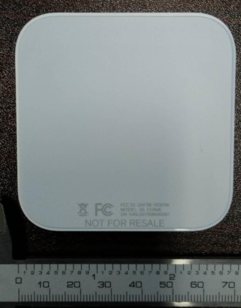
Click to zoom
Application Details
- Equipment Class
- DTS - Digital Transmission System
- Date of Grant
- Dec 01, 2015
- Application Purpose
- Original Equipment
- Date of Application
- Dec 01, 2015
- Equipment Note
- Mobile credit card reader
- Frequency Range
- 2402.00000000 - 2480.00000000
- Company
- Block, Inc.
- Country
- United States
Documents & Files
Document Text
Text extracted from the exhibit documents filed with the FCC. Open a document above to read the original.
Users Manual
1455 Market Street, Suite 600, San Francisco, CA 94103 APPROVALS PROJECT R12 Retail Packaging DELIVERABLE GSG - US INKS 2/2 + OA Matte AQ CREATIVE Approved Changes IMAGING Approved Changes COPY Approved Changes LOCALIZATION Approved Changes EDITING Approved Changes LEGAL Approved Changes REQUESTOR Approved Changes PRODUCER Approved Changes DESIGN Eric Manago SIZE Flat: 208mm x 104mm Finished: 104mm x 104mm BLACK + PMS CG7 PRODUCTION Jordan Lebrecht STOCK 250g C2S MODIFIED September 2, 2015 11:12 AM FINISHING Die cut, fold NOTE Part #: M-LIT-0060-01 REV-02: Art change for MP VERSION M02 VENDOR RR Donnelly - China FILE NAME M-LIT-0060-02_R12+R4_GSG_US_M02 Contactless + Chip Cards RETURNS Square guarantees a 30-day, risk-free return policy for all purchases made through the Square Shop online. After a return is complete, a refund will be credited back to you. Visit square.com/returns to learn more. If you purchased your reader from another retailer, please check with them about their return policy. ONE-YEAR WARRANTY If something goes wrong with your reader, you’re covered for up to one year—no matter where you purchased it. Visit square.com/warranty for more details. This device complies with part 15 of the FCC Rules. Operation is subject to the following two conditions: (1) This device may not cause harmful interference, and (2) this device must accept any interference received, including interference that may cause undesired operation. © 2015 Square, Inc. Square, the Square logo, and Square Reader are trademarks of Square, Inc. M-LIT-0060-02 square.com Stick it here, there, or anywhere. COUNTERTOPSTOREFRONT GET UP AND RUNNING Open the Square app to get started. If you’re new to Square, download the Square app from the App Store or Google Play to create an account. If you’re already using Square, make sure you’re running the latest version. Open the app and tap the menu icon ( ) > Settings > Card Readers. Follow the setup instructions from there. Learn more online. For complete instructions, visit square.com/setup. Take a guided tour of your new readers and get in touch with any questions. ALL PAYMENT TYPES WELCOME Let your customers know you accept all major credit cards— whether it’s a chip card, a magstripe card, or through contactless payments like Apple Pay. 1455 Market Street, Suite 600, San Francisco, CA 94103 APPROVALS PROJECT R12 Retail Packaging DELIVERABLE FCC Legal Insert - US INKS 1/0 + OA AQ w/ Bleeds, Heavy Coverage CREATIVE Approved Changes IMAGING Approved Changes COPY Approved Changes LOCALIZATION Approved Changes EDITING Approved Changes LEGAL Approved Changes REQUESTOR Approved Changes PRODUCER Approved Changes DESIGN Eric Manago SIZE Flat: 104mm x 104mm PMS CG7 PRODUCTION Jordan Lebrecht STOCK 70gsm C2S MODIFIED December 1, 2015 5:16 PM FINISHING Die cut, matte varnish NOTE Part #: M-LIT-0084-01 VERSION M02 QUANTITY XX pieces FILE NAME M-LIT-0084-01_R12_FCC_Insert_US_M02 This device complies with part 15 of the FCC Rules. Operation is subject to the following two conditions: (1) This device may not cause harmful interference, and (2) this device must accept any interference received, including interference that may cause undesired operation. NOTE: The grantee is not responsible for any changes or modifications not expressly approved by the party responsible for compliance. Such modifications could void the user’s authority to operate the equipment. IMPORTANT NOTE: FCC RF Radiation Exposure Statement: This equipment complies with FCC RF radiation exposure limits set forth for an uncontrolled environment. This equipment should be installed and operated with a minimum distance of 20cm between the radiator and any part of your body. NOTE: This equipment has been tested and found to comply with the limits for a Class B digital device, pursuant to part 15 of the FCC Rules. These limits are designed to provide reasonable protection against harmful interference in a residential installation. This equipment generates uses and can radiate radio frequency energy and, if not installed and used in accordance with the instructions, may cause harmful interference to radio communications. However, there is no guarantee that interference will not occur in a particular installation. If this equipment does cause harmful interference to radio or television reception, which can be determined by turning the equipment off and on, the user is encouraged to try to correct the interference by one or more of the following measures: • Reorient or relocate the receiving antenna. • Increase the separation between the equipment and receiver. • Connect the equipment into a circuit different from that to which the receiver is connected. • Consult the dealer or an experienced radio/TV technician for help. © 2015 Square, Inc. M-LIT-0084-01
External Photos
EUT – External view 1 EUT – External view 2 EUT – External view 3
ID Label/Location Info
A work BenBenBen Su aceCMFA work FormatDateRemarkProject R12_b 2015/10/30 Confidential for internal use only Color: Mid Gray, Pantone 428U Finish: Glossy Note: Please align the oval graphic to center of R12 Color: Mid Gray, Pantone 427U Finish: Matte 7.15mm 11.97mm SQ Market “Light” vector graph 1234567890123456 1234567890123456 1234567890123456
ID Label/Location Info
A work BenBenBen Su aceCMFA work FormatDateRemarkProject R12_b 2015/10/30 Confidential for internal use only Color: Mid Gray, Pantone 428U Finish: Glossy Note: Please align the oval graphic to center of R12 Color: Mid Gray, Pantone 427U Finish: Matte 7.15mm 11.97mm SQ Market “Light” vector graph 1234567890123456 1234567890123456 1234567890123456
Internal Photos
EUT – Internal view 1 Enclosure Cover removed BLE antenna EUT – Internal view 2 PCB, side 1, with cage EUT – Internal view 3 PCB, side 1, cage removed EUT – Internal view 4 PCB, side 1, cage removed, alternate angle BLE antenna Contact card socket soldered directly onto PCB. Not a shield. There are no components under this part. EUT – Internal view 5 PCB, side 2, with battery in place EUT – Internal view 6 PCB, side 2, battery removed EUT – Internal view 7 NFC antenna, mounted to housing 13.56 MHz antenna
RF Exposure Info
Maximum Permissible Exposure Square Inc. S6 FCC ID: 2AF3K-1SQHW Purpose The purpose of this test is to ensure that the RF energy intentionally transmitted, in terms of power density emitted from the EUT at a stated operating distance does not exceed the limits listed below as defined in the applicable test standard, as calculated based upon readings obtained during testing. This helps protect human exposure to excessive RF fields. Limit(s) and Method The limits, as defined in FCC 1.1310 Table 1 (B) limits for general public exposure was applied. The limit for the frequency range of 1.34 MHz to 30 MHz is 180/f 2 mW/cm 2 , and the limit for the frequency range of 1.5 GHz to 100 GHz is 1.0 mW/cm 2 . Therefore, the limits for this device are as follows: MPE Limits Frequency Limit 13.56 MHz 0.97 mW/cm 2 2.4 – 2.4835 GHz 1.0 mW/cm 2 The distance used for calculations was 20cm, as this is the minimum distance a user will be from the EUT during normal operation. Prediction methods from OET Bulletin 65, Edition 97-01 are applied. SAR test exclusion for simultaneous transmissions from FCC KDB447498 is applied. Radiated data was measured at a distance of 3m. Results The EUT passed the requirements. The worst case calculated power densities of all transmitters are under limits, and the sum of the MPE ratios meet the MPE test exclusion requirement for simultaneous transmissions. Calculations for 15.247 device P d = (EIRP / (4*pi*R 2 ) Where: EIRP = Equivalent Isotropic Radiated Power = E(dBuV) – 95.2 E(dBuV) = 92.2 dBuV EIRP = 92.2 dBuV – 95.2 = -3.0 dBm = 0.5012 mW R = 20cm P d = (0.5012 mW) / (4 * pi * 20 2 cm 2 ) P d = 0.000099711 mW/cm 2 Calculations for 15.209 device P d = (EIRP / (4*pi*R 2 ) Where: EIRP = Equivalent Isotropic Radiated Power = E(dBuV) – 95.2 E(dBuV) = 75.9 dBuV EIRP = 75.9 dBuV – 95.2 = -19.3 dBm = 0.01175 mW R = 20cm P d = (0.01175 mW) / (4 * pi * 20 2 cm 2 ) P d = 0.000002338 mW/cm 2 Calculations for simultaneous transmission device As per FCC KDB447498 7.2: Simultaneous transmission MPE test exclusion applies when the sum of the MPE ratios for all simultaneous transmitting antennas incorporated in a host device, based on the calculated/estimated, numerically modeled or measured field strengths or power density, is ≤ 1.0. MPE ratio = Ratio of power density to MPE limit, at the test frequency = P d / (MPE limit) MPE ratio for 15.247 device = 0.000099711 mW/cm 2 / 1.0 mW/cm 2 = 0.000099711 MPE ratio for 15.209 device = 0.000002338 mW/cm 2 / 0.97 mW/cm 2 = 0.0000024104 0.000099711 + 0.0000024104 = 0.0001021214 < 1.0 MPE test exclusion applies for simultaneous transmission.
Test Report
LAB REGISTRATION #6844A-3 FCC REGISTRATION #377448 Testing Laboratory Certificate #2555.01 Page 1 of 94 Report issue date: 11/29/2015 GEMC File #: GEMC-FCC-23230AR1 © Global EMC Inc. This test report shall not be reproduced except in full, without written approval of Global EMC Inc. This report is based on GEMC Template “FCC 15 247 Rev2.” Global EMC Inc. Labs EMC & RF Test Report As per FCC Part 15 Subpart C:2015 & RSS 247:2015 Unlicensed Intentional Radiators on the S6 Mobile Credit Card Reader Raymond Lee Au, B.Eng Project Engineer Global EMC Inc. 11 Gordon Collins Dr. Gormley, ON L0H 1G0, Canada Ph: (905) 883-8189 Testing produced for See Appendix A for full customer & EUT details. Client Square Inc. Product S6 Mobile Credit Card Reader Standard(s) FCC Part 15 Subpart C 15:2015 / RSS-247:2015 Page 2 of 94 Report issue date: 11/29/2015 GEMC File #: GEMC-FCC-23230AR1 © Global EMC Inc. This test report shall not be reproduced except in full, without written approval of Global EMC Inc. Table of Contents Table of Contents ................................................................................................................... 2 Report Scope .......................................................................................................................... 3 Summary ................................................................................................................................ 4 Test Results Summary ....................................................................................................... 5 Notes, Justifications, or Deviations ................................................................................... 6 Applicable Standards, Specifications and Methods ........................................................... 7 Sample calculation(s) ......................................................................................................... 8 Document Revision Status ................................................................................................. 8 Definitions and Acronyms ..................................................................................................... 9 Testing Facility .................................................................................................................... 10 Calibrations and Accreditations ....................................................................................... 10 Testing Environmental Conditions and Dates ................................................................. 11 Detailed Test Results Section .............................................................................................. 12 6 dB Bandwidth of Digitally Modulated Systems ........................................................... 13 Maximum Peak Conducted Power - Digital Modulation ................................................ 19 Maximum Peak Radiated Power - Digital Modulation.................................................... 25 Antenna Spurious Conducted Emissions (-20 dBc Requirement) ................................... 34 Power Spectral Density - Digital Modulation .................................................................. 40 Radiated Emissions – 15.247, 15.209 .............................................................................. 45 Power Line Conducted Emissions ................................................................................... 71 Appendix A – EUT Summary .............................................................................................. 77 Appendix B – EUT and Test Setup Photographs................................................................. 78 Client Square Inc. Product S6 Mobile Credit Card Reader Standard(s) FCC Part 15 Subpart C 15:2015 / RSS-247:2015 Page 3 of 94 Report issue date: 11/29/2015 GEMC File #: GEMC-FCC-23230AR1 © Global EMC Inc. This test report shall not be reproduced except in full, without written approval of Global EMC Inc. Report Scope This report addresses the EMC testing and test results of the S6 Mobile Credit Card Reader from Square Inc. This unit is herein referred to as EUT (Equipment Under Test). Testing is performed at Global EMC Labs. The EUT was tested for compliance against the following standards: FCC Part 15 Subpart C:2015 RSS 247:2015 Test procedures, results, justifications, and engineering considerations, if any, follow later in this report. The results contained in this report relate only to the item(s) tested. This report does not imply product endorsement by A2LA or any other accreditation agency, any government, or Global EMC Inc. Opinions/interpretations expressed in this report, if any, are outside the scope of Global EMC Inc accreditation. Any opinions expressed do not necessarily reflect the opinions of Global EMC Inc, unless otherwise stated. Client Square Inc. Product S6 Mobile Credit Card Reader Standard(s) FCC Part 15 Subpart C 15:2015 / RSS-247:2015 Page 4 of 94 Report issue date: 11/29/2015 GEMC File #: GEMC-FCC-23230AR1 © Global EMC Inc. This test report shall not be reproduced except in full, without written approval of Global EMC Inc. Summary The results contained in this report relate only to the item(s) tested. EUT FCC Certification #, FCC ID: 2AF3K-1SQHW EUT Passed all tests performed. Yes (see test results summary) Tests conducted by Raymond Lee Au Client Square Inc. Product S6 Mobile Credit Card Reader Standard(s) FCC Part 15 Subpart C 15:2015 / RSS-247:2015 Page 5 of 94 Report issue date: 11/29/2015 GEMC File #: GEMC-FCC-23230AR1 © Global EMC Inc. This test report shall not be reproduced except in full, without written approval of Global EMC Inc. Test Results Summary Standard/Method Description Class/Limit Result FCC 15.203 Antenna Requirement Unique Pass FCC 15.205 RSS-Gen 8.10 (Table 6) Restricted Bands for intentional operation QuasiPeak Average Pass FCC 15.209 RSS-Gen 8.9 (Table 4 & 5) Spurious Radiated emissions QuasiPeak Average Pass FCC 15.247(a)2 RSS-247 5.2…
Text truncated - open the document above for the full version.
Test Setup Photos
Radiated Emissions Photo 1 Radiated Emissions Photo 2 Radiated Emissions Photo 3 Radiated Emissions Photo 4 Conducted Measurements Power Line Conducted Emissions
Contact Information
Applicant
Gavin Demonte
Test Firm
TUV SUD CANADA (Gormley)William (Mac) Elliott
[email protected]813-284-2736
Technical Specifications
| # | Rule Parts | Frequency Range | Power Output |
|---|---|---|---|
| 1 | 15C | 2.40 GHz - 2.48 GHz | 200.00 µW |
Other Applications from Block, Inc.
2AF3K-BK003
Mar 25, 2026Block Bitkey
Equipment Class
DXX - Part 15 Low Power Communication Device Transmitter2AF3K-SPS5
Jan 06, 2026Customer display
Equipment Class
DXX - Part 15 Low Power Communication Device Transmitter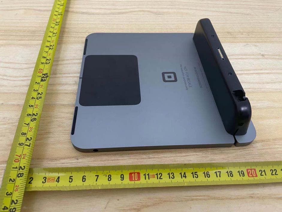
2AF3K-SPS4
Jan 07, 2021Customer Display (Square Register)
Equipment Class
JAB - Part 15 Class B Digital Device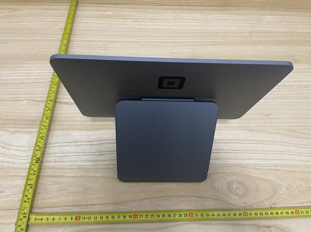
2AF3K-SPS1
Jan 07, 2021Square Register
Equipment Class
DTS - Digital Transmission System
2AF3K-SPD2
Jul 22, 2020Square Terminal
Equipment Class
JAB - Part 15 Class B Digital Device