2AF5PMG8702DOCSIS 3.1 Cable Modem plus AC3200 Router
MTRLC LLC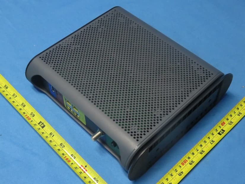
Click to zoom
Application Details
- Equipment Class
- DTS - Digital Transmission System
- Date of Grant
- Feb 26, 2020
- Application Purpose
- Original Equipment
- Date of Application
- Feb 26, 2020
- Equipment Note
- DOCSIS 3.1 Cable Modem plus AC3200 Router
- Frequency Range
- 2412.00000000 - 2462.00000000
- Company
- MTRLC LLC
- Country
- United States
Documents & Files
Document Text
Text extracted from the exhibit documents filed with the FCC. Open a document above to read the original.
Users Manual
Quick Start DOCSIS 3.1 Cable Modem plus AC3200 Router MG8702 Packaged with your MG8702 modem/router Power Cube Coax Wrench Ethernet Cable Velcro ® Cable Organizer Para una Guía de Inicio Rápido en español, por favor vaya a www.motorolanetwork.com/MG8702ir Let’s get started If you don’t have cable Internet service, please order that from your cable service provider. MG8702 supports DOCSIS 3.1, the fastest cable modem service standard. Your MG8702 also supports all speeds of any DOCSIS 3.0 services. Now connect your MG8702 as shown on the next panel. Connecting to a Coax Cable Please see the connection photo on the next panel. You connect your MG8702 to a “live” coax cable. Sometimes a cable will already be available. Sometimes there’s a coax wall jack available, and you connect to the jack with a coax cable. Your MG8702 can also share a coax cable attached to a TV by using a coax splitter. Please note that a badly chosen splitter reduces a cable modem's speed; so if you need to use a splitter, use a 2-way splitter whose top frequency is 1,000 MHz or higher. USB Port WPS button WLAN button WiFi on/off button RESET ETHERNET (LAN 1-4) You can connect a computer, HDTV, game station, or other Ethernet-capable device to any of these 4 LAN ports. COAX Connect a “live” coax cable to the modem’s COAX connector as discussed above. (Tighten the nut so it’s finger tight. You may want to use the supplied wrench. Make the connection snug but not over- tight.) ON/OFF button POWER Connect the supplied power cube between the power jack and an electrical outlet. Prepare to activate By now you should have: • Subscribed to cable Internet service. • Connected your MG8702. • Powered up your cable modem/router. To do this, the On/Off button needs to be On (Push the button in until it clicks). Wait for the online connection light ( for 3.0, or for 3.1) to stop flashing and remain solidly lit. This may take up to 15 minutes. You should have a recent cable bill handy because it has your account number and you’ll probably need that. If you’re asked for information about the MG8702, you can find this on the label on the bottom of the modem/router. Activate For some service providers, you activate by calling them. Many service providers including Comcast and Cox prefer that you activate by opening the Web browser of a computer that’s plugged into one of the MG8702’s Ethernet ports. Once you've opened the browser, try to go to www.motorola.com . This should bring you to the service provider's activation page. If you don’t have a computer, you can use the Web browser of a WiFi device such as a smartphone or tablet for activation. In that case you’ll need the unique Wireless Network Name and Password printed on the bottom of your MG8702. You’ll use these in setting up your wireless device to connect to the MG8702. Once you’ve connected, you can open the browser of that wireless device. For Comcast XFINITY Users Only: If the activation page does not appear, please go to xfinity.com/activate for more information and to activate your modem. Here is a list of phone numbers for some major cable service providers. (Note that this list is subject to change.) Comcast 1 (800) XFINITY Cox 1 (877) 206-4210 Bright House (Spectrum) 1 (855) 222-0102 Cable One 1 (855) 692-4113 Charter Spectrum 1 (855) 757-7328 MediaCom RCN 1 (844) 987-3260 1 (800) 746-4726 Suddenlink 1 (877) 794-2724 Time Warner (Spectrum) WOW! 1 (855) 707-7328 1 (800) 343-2076 Once your MG8702 is activated either online or by phone, your service provider will provision your MG8702 service. Typically this takes less than 5 minutes, but in some cases this may take 30 minutes or longer to complete. Once you have activated, try to browse the Web using a device connected via Ethernet or WiFi to the MG8702. (See the section Wireless Router, below for information on connecting via WiFi). If browsing works, Congratulations! Your MG8702 is working. If your MG8702 is NOT working, see Troubleshooting Tips below. Configuration Manager You may not need to use the MG8702’s Configuration Manager. Here are some reasons for using it: • You want to change the wireless network name and password. For instance, maybe you want a more easily remembered name, or you're replacing a router and want to use your existing WiFi Network Name (SSID) and/or WiFi Password/Key instead of the unique ones that come with the MG8702. (See WiFi setup page.) • You want to set up special Internet gaming settings. • You want to get performance information about the MG8702 modem and/or built-in router. This can be helpful in diagnosing DOCSIS performance issues and/or optimizing wireless performance. If you need to access the MG8702 Configuration Manager, open your Web browser. Type http://192.168.0.1 in the address bar and press the Enter key. In the login dialog box, type the following User Name and Password in lower case, then click OK. User Name: admin Password: motorola The Basic Status and Settings page will appear. If this page doesn’t appear, please see the Troubleshooting Tips below. You can get more detailed information about the MG8702 and its Configuration Manager, please see www.motorolanetwork.com/MG8702manual Wireless Router As noted before, the MG8702 has a unique Wireless Network Name/SSID and Wireless Security Key/Password printed on the MG8702’s bottom label. Set up your wireless devices to work with this SSID and security key, or the SSID and security key you specified, if you changed them. Note that wireless performance depends on a number of factors. Please keep these things in mind: • Where possible, put the MG8702 in a central place so that it’s not too far away from your other wireless devices. • Try to avoid interference from other wireless devices such as Bluetooth headsets and stereos, microwave ovens, WiFi- capable printers, and 2.4 GHz cordless phones and base stations. Don’t put the MG8702 close to these interfering devices. • Sometimes it helps to change the MG8702 wireless chan…
Text truncated - open the document above for the full version.
Cover Letter(s)
Declaration of Authorization We, Name: MTRLC LLC Address: 225 Franklin Street, 26th Floor City: Boston State,Zip: MA 02110 Country: United States Declare that: Name Representative of agent: Ms. Mandy Wang Agent Company name: BTL Inc. Address: No.3 Jinshagang 1st Road, Shixia, Dalang Town City: Dong Guan Country: China is authorized to apply for Certification and signing related documents of the following product(s), including 731 form(s), on our behalf: Product description: DOCSIS 3.1 Cable Modem plus AC3200 Router Type designation: MG8702XY (Where X can be A,B,C,D or blank, and Y can be A,B,C,D or blank. The optional suffixes X and Y are to be used for identical hardware models that differ for marketing/sales purposes only.) Trademark: Motorola FCC ID: 2AF5PMG8702 Date: 2019-12-26 City: Boston Name: Andy Pollock Function: Director of Hardware Signature: ............................... Notes: (1): Required for FCC application (2): For FCC it must be the Grantee Code “owner” or the authorized agent.
Cover Letter(s)
CONFIDENTIALITY REQUEST for Certification Service in USA Federal Communication Commission Equipment Authorization Division, Application Processing Branch 7435 Oakland Mills Road Columbia, MD 21048 <2019-12-26> TO WHOM IT MAY CONCERN: Pursuant to Paragraphs §0.457 and 0.459 of the Commission’s Rules (47 C.F.R.) and Section §552(b)(4) of the Freedom of Information Act, we request confidentiality for the following products: FCC ID Model name 2AF5PMG8702 MG8702XY For the product stated above, we request that the following information be held confidential; Exhibits Long-Term Confidentiality Short-Term Confidentiality Short-Term Confidentiality Days External Photos Internal Photos Block Diagram Schematics Test Setup Photos User’s Manual Parts List Tune Up Operational Descriptions The long-term confidentiality exhibits contain our trade secrets and proprietary information that could be of benefit to our competitors. The short-term confidentiality on the basis of ensuring that business sensitive information remains confidential until the actual marketing of our new device. If you have any questions, please feel free to contact me at the address shown below. Sincerely, Name: Andy Pollock, Director of Hardware Company: MTRLC LLC Address: 225 Franklin Street, 26th Floor, Boston, Massachusetts, 02110 United States Phone: 6177530663 Fax: 617-423-1075 E-Mail: [email protected]
Cover Letter(s)
MTRLC LLC Wi-Fi Channel 12 and 13 Declaration Letter Date: 2019-12-26 We, the undersigned company Company Name: MTRLC LLC Address: 225 Franklin Street, 26th Floor, Boston, Massachusetts, 02110, United States Declare that: Product Description: DOCSIS 3.1 Cable Modem plus AC3200 Router Type designation: MG8702XY (Where X can be A,B,C,D or blank, and Y can be A,B,C,D or blank. The optional suffixes X and Y are to be used for identical hardware models that differ for marketing/sales purposes only.) Brand: Motorola FCC ID: 2AF5PMG8702 Only channels 1~11 will be used in USA. Country code selection is disabled. If you have any questions regarding the authorization, please do not hesitate to contact us, thank you. Sincerely, Signature: ________________________ Name: Andy Pollock, Director of Hardware Engineering Tel: 6177530663 Email: [email protected]
External Photos
Project No.: 1908C159 Page 2 of 13 Project No.: 1908C159 Page 3 of 13 Project No.: 1908C159 Page 4 of 13 Project No.: 1908C159 Page 5 of 13
ID Label/Location Info
Notes: 1) Material : Black Text on White Polyester or equivalent with Permanent adhesive, must meet UL Rub test requirements 2)The serial number will be of the Format DDDY-XXXXXX-NNNN where: DDD = the Julian date of the day manufacture. Example January 1 is 001, Feb 1 is 032, December 31 = 365. Tolerance = +/- 3 days Y= the significant digit of the Year of manufacture. Example 2010 = 0, 2011=1, 2017=7. XXXXXX= the exact Model Number of the Product. (MG8702) #### = a sequential number from 0001 to 9999 that indicates the number of the unit produced of that type, on that day. 3) ZZZZZZZZSSSS represents the MAC Address. 4) Default SSID to be “MOTOSSSS” where SSSS is the last 4 digits of the CM MAC. 5) Wireless Security Key/Password "Word1Word2nnn" is constructed as a randomly chosen word from the Zoom “Friendly Passphrase” file’s adjective column (Word1), a randomly chosen word from the noun column (Word2), and a randomly selected 3-digit number “nnn” that cannot contain a 0 or a 1 (must use only digits 2,3,4,5,6,7,8,9). For example, “PlasticBarn352”. 6) Add Code 128 barcodes to empty space shown in 4 locations: under WiFi Network SSID, WiFi Password, S/N, and CM MAC fields. The barcode content is to contain the same unique per-unit data as the field above it, not including “S/N:” or “CM MAC:”. 7) All Code 128 barcodes should fit the available space, minimum height is 4 mm 8) Add QR code image in location as shown by example below, size 20mmx20mm. QR code content to be as follows: W IFI:T:WPA2;S:MOTOSSSS;P: word1word2nnn;;DEVICE:M:ZZZZZZZZSSSS;S: DDDY-MG8702-####;T:MG8702;; W here above text in red is static, always included exactly as shown. The above text in blue is variable and shall be as described in the above notes 2, 3, 4 and 5. 9) Label Size is 167 mm x 67 mm, three 1mm radiused corners and one C2.2mm wedge-cut corner as shown Zoom Telephonics Inc 99 High Street, Boston, MA 02110 USA P ROPRIETARY AND CONFIDENTIAL THE INFORMATION CONTAINED IN THIS DRAWING IS THE SOLE PROPERTY OF Zoom Telephonics, Inc. ANY REPRODUCTION IN PART OR AS A WHOLE WITHOUT THE WRITTEN PERMISSION OF Zoom Telephonics, Inc IS PROHIBITED. TITLE: Labe l, MG8702 Compliance Pre-P roduction Version UN LESS OTHERWISE S PECIFIED: S IZE A NAME DATE DRAWN CHECKED ENG APPR. MFG APPR. Q.A. COMMENTS: DW G. NO. 3 64XX-1 REV P0 DIM ENSIONS ARE IN MM TOL ERANCES: FRACTIONAL +/- ANGULAR: MACH +/- BEND +/- TWO PLACE DECIMAL +/- THREE PLACE DECIMAL +/- I NTERPRET GEOMETRIC TOL ERANCING PER: M ATERIAL: F INISH: US ED ON N EXT ASSY 67mm 167m m Made in China to MTRLC LLC's Specifications This device complies with Part 15 of the FCC Rules. Operation is sub j ect to the following two conditions: (1) This device may not cau se harmful interference, and (2) t his device must accept any interference received, including i nterference that may cause undes ired operation. Router Configur ation IP Address: 192.168.0.1 User Name: admin Password: motorola Po wer: +12VDC 3.5A FC C ID: 2 AF5PMG8702 MTRL C LLC motor olanetwork.com D OCSIS 3.1 Cable Gateway Model: MG8702 S/ N: 2 039 -MG 8702 -2 495 CM MA C : 0 040364E373A D efault WiFi Settings WiFi Network (SSID): MOT O373A WiFi Password: GreenBird583 C2. 2 mm wed ge cut 1m m radius 3 places VEC A
Internal Photos
Project No.: 1908C159 Page 6 of 13 2.4G+5G Ant.3 2.4G+5G Ant.4 2.4G+5G Ant.2 2.4G+5G Ant.1 Project No.: 1908C159 Page 7 of 13 Project No.: 1908C159 Page 8 of 13 Project No.: 1908C159 Page 9 of 13 Project No.: 1908C159 Page 10 of 13 Project No.: 1908C159 Page 11 of 13 Project No.: 1908C159 Page 12 of 13 Project No.: 1908C159 Page 13 of 13
RF Exposure Info
Report No.: BTL-FCCP-3-1908C159 Page 1 of 6 FCC RF EXPOSURE REPORT FCC ID: 2AF5PMG8702 Project No. : 1908C159 Equipment : DOCSIS 3.1 Cable Modem plus AC3200 Router Brand Name : motorola Test Model : MG8702XY Series Model : N/A Applicant : MTRLC LLC Address : 225 Franklin St. 26th Floor, Boston, MA 02110 Manufacturer : MTRLC LLC Address : 225 Franklin St. 26th Floor, Boston, MA 02110 Date of Receipt : Aug. 20, 2019 Date of Test : Aug. 26, 2019 ~ Oct. 24, 2019 Issued Date : Jan. 21, 2020 Report Version : R00 Test Sample : Engineering Sample No.: DG19082034 Standard(s) : FCC Guidelines for Human Exposure IEEE C95.1 FCC Title 47 Part 2.1091, OET Bulletin 65 Supplement C The above equipment has been tested and found compliance with the requirement of the relative standards by BTL Inc. Prepared by : Kai Xu Approved by : Ethan Ma Add: No.3, Jinshagang 1st Road, Shixia, Dalang Town,Dongguan, Guangdong, China. Te l : +86-769-8318-3000 Web: www.newbtl.com Report No.: BTL-FCCP-3-1908C159 Page 2 of 6 REPORT ISSUED HISTORY Report Version Description Issued Date R00 Original Issue Jan. 21, 2020 Report No.: BTL-FCCP-3-1908C159 Page 3 of 6 1. MPE CALCULATION METHOD Calculation Method of RF Safety Distance: where: S = power density P = power input to the antenna G = power gain of the antenna in the direction of interest relative to an isotropic radiator R = distance to the center of radiation of the antenna Report No.: BTL-FCCP-3-1908C159 Page 4 of 6 Antenna Specification: For 2.4GHz: Ant. Brand Model Name Antenna Type Connector Gain (dBi) 1 N/A N/A Internal N/A 3.00 2 N/A N/A Internal N/A 3.00 3 N/A N/A Internal N/A 3.00 4 N/A N/A Internal N/A 3.00 Note: (1) For Non Beamforming function: This EUT supports CDD, and all antennas have the same gain, Directional gain = G ANT +Array Gain, where Array Gain is as follows: For power spectral density measurements, N ANT = 4, N SS = 1. So Directional gain = G ANT + Array Gain =3.00+10 log (N ANT / N SS ) dB =3.00+10log(4/1)dBi =9.02. Then, the power spectral density limit is 8-9.02+6=4.98. For power measurements, Array Gain = 0 dB (N ANT ≤ 4), so the Directional gain=3.00. (2) For Beamforming function, Beamforming Gain: 6.00 dB. So Directional gain = 6.00+3.00=9.00. Then, output power limit is 30-9.00+6=27.00. For 5GHz: Ant. Brand Model Name Antenna Type Connector Gain (dBi) 1 N/A N/A Internal N/A 3.00 2 N/A N/A Internal N/A 3.00 3 N/A N/A Internal N/A 3.00 4 N/A N/A Internal N/A 3.00 Note: (1) For Non Beamforming function: This EUT supports CDD, and all antennas have the same gain, Directional gain = G ANT +Array Gain, where Array Gain is as follows: For power spectral density measurements, N ANT = 2, N SS = 1. So Directional gain = G ANT + Array Gain =10 log (N ANT / N SS ) dB =3.00+10log(2/1)dBi=9.02. Then, the UNII-1 power spectral density limit is 17-9.02+6=13.98, the UNII-3 power spectral density limit is 30-9.02+6=26.98. For power measurements, Array Gain = 0 dB (N ANT ≤ 4), so the Directional gain=3.00. (2) For Beamforming function, Beamforming Gain: 6.00 dB. So Directional gain = 6.00+3.00=9.00. Then, UNII-1 and UNII-3 output power limit is 30-9.00+6=27.00. Report No.: BTL-FCCP-3-1908C159 Page 5 of 6 2. TEST RESULTS For 2.4GHz Non Beamforming: Directional Gain (dBi) Directional Gain (numeric) Max. Output Power (dBm) Max. Output Power (mW) Power Density (S) (mW/cm 2 ) Limit of Power Density (S) (mW/cm 2 ) Te s t Result 3.00 1.9953 29.94 986.2795 0.25069 1 Complies For 2.4GHz Beamforming: Directional Gain (dBi) Directional Gain (numeric) Max. Output Power (dBm) Max. Output Power (mW) Power Density (S) (mW/cm 2 ) Limit of Power Density (S) (mW/cm 2 ) Te s t Result 9.00 7.9433 26.64 461.3176 0.46680 1 Complies For 5GHz UNII-1 Non Beamforming: Directional Gain (dBi) Directional Gain (numeric) Max. Output Power (dBm) Max. Output Power (mW) Power Density (S) (mW/cm 2 ) Limit of Power Density (S) (mW/cm 2 ) Te s t Result 3.00 1.9953 26.79 477.5293 0.12138 1 Complies For 5GHz UNII-3 Non Beamforming: Directional Gain (dBi) Directional Gain (numeric) Max. Output Power (dBm) Max. Output Power (mW) Power Density (S) (mW/cm 2 ) Limit of Power Density (S) (mW/cm 2 ) Te s t Result 3.00 1.9953 28.73 746.4488 0.18973 1 Complies For 5GHz UNII-1 Beamforming: Directional Gain (dBi) Directional Gain (numeric) Max. Output Power (dBm) Max. Output Power (mW) Power Density (S) (mW/cm 2 ) Limit of Power Density (S) (mW/cm 2 ) Te s t Result 9.00 7.9433 26.01 399.0249 0.40377 1 Complies For 5GHz UNII-3 Beamforming: Directional Gain (dBi) Directional Gain (numeric) Max. Output Power (dBm) Max. Output Power (mW) Power Density (S) (mW/cm 2 ) Limit of Power Density (S) (mW/cm 2 ) Te s t Result 9.00 7.9433 26.77 475.3352 0.48098 1 Complies Report No.: BTL-FCCP-3-1908C159 Page 6 of 6 For the max simultaneous transmission MPE: Power Density (S) (mW/cm 2 ) Power Density (S) (mW/cm 2 ) To t a l Limit of Power Density (S) (mW/cm 2 ) Test Result 2.4GHz 5GHz 0.46680 0.48098 0.94778 1 Complies Note: The calculated distance is 25 cm. Output power including tune up tolerance. End of Test Report
Test Report
Report No.: BTL-FCCP-1-1908C159 Page 1 of 119 FCC Radio Test Report FCC ID: 2AF5PMG8702 This report concerns: Original Grant Project No. : 1908C159 Equipment : DOCSIS 3.1 Cable Modem plus AC3200 Router Brand Name : motorola Test Model : MG8702XY Series Model : N/A Applicant : MTRLC LLC Address : 225 Franklin St. 26th Floor, Boston, MA 02110 Manufacturer : MTRLC LLC Address : 225 Franklin St. 26th Floor, Boston, MA 02110 Date of Receipt : Aug. 20, 2019 Date of Test : Aug. 26, 2019 ~ Oct. 24, 2019 Issued Date : Jan. 21, 2020 Report Version : R00 Test Sample : Engineering Sample No.: DG19082034 for conducted, DG19082033 for radiated Standard(s) : FCC Part15, Subpart C (15.247) ANSI C63.10-2013 KDB 558074 D01 15.247 Meas Guidance v05r02 The above equipment has been tested and found compliance with the requirement of the relative standards by BTL Inc. Prepared by : Welly Zhou Approved by : Ethan Ma Add: No.3, Jinshagang 1st Road, Shixia, Dalang Town,Dongguan, Guangdong, China. Te l : +86-769-8318-3000 Web: www.newbtl.com Report No.: BTL-FCCP-1-1908C159 Page 2 of 119 Declaration BTL represents to the client that testing is done in accordance with standard procedures as applicable and that test instruments used has been calibrated with standards traceable to international standard(s) and/or national standard(s). BTL's reports apply only to the specific samples tested under conditions. It is manufacture’s responsibility to ensure that additional production units of this model are manufactured with the identical electrical and mechanical components. BTL shall have no liability for any declarations, inferences or generalizations drawn by the client or others from BTL issued reports. The report must not be used by the client to claim product certification, approval, or endorsement by NVLAP, NIST, A2LA, or any agency of the U.S. Government. This report is the confidential property of the client. As a mutual protection to the clients, the public and ourselves, the test report shall not be reproduced, except in full, without our written approval. BTL’s laboratory quality assurance procedures are in compliance with the ISO/IEC 17025 requirements, and accredited by the conformity assessment authorities listed in this test report. BTL is not responsible for the sampling stage, so the results only apply to the sample as received. The information, data and test plan are provided by manufacturer which may affect the validity of results, so it is manufacturer’s responsibility to ensure that the apparatus meets the essential requirements of applied standards and in all the possible configurations as representative of its intended use. Limitation For the use of the authority's logo is limited unless the Test Standard(s)/Scope(s)/Item(s) mentioned in this test report is (are) included in the conformity assessment authorities acceptance respective. Please note that the measurement uncertainty is provided for informational purpose only and are not use in determining the Pass/Fail results. Report No.: BTL-FCCP-1-1908C159 Page 3 of 119 Table of Contents Page REPORT ISSUED HISTORY 6 1 . SUMMARY OF TEST RESULTS 7 1.1 TEST FACILITY 8 1.2 MEASUREMENT UNCERTAINTY 8 1.3 TEST ENVIRONMENT CONDITIONS 8 2 . GENERAL INFORMATION 9 2.1 GENERAL DESCRIPTION OF EUT 9 2.2 DESCRIPTION OF TEST MODES 11 2.3 PARAMETERS OF TEST SOFTWARE 13 2.4 DUTY CYCLE 14 2.5 BLOCK DIAGRAM SHOWING THE CONFIGURATION OF SYSTEM TESTED 15 2.6 SUPPORT UNITS 15 3 . AC POWER LINE CONDUCTED EMISSIONS TEST 16 3.1 LIMIT 16 3.2 TEST PROCEDURE 16 3.3 DEVIATION FROM TEST STANDARD 16 3.4 TEST SETUP 17 3.5 EUT OPERATION CONDITIONS 17 3.6 TEST RESULTS 17 4 . RADIATED EMISSIONS TEST 18 4.1 LIMIT 18 4.2 TEST PROCEDURE 19 4.3 DEVIATION FROM TEST STANDARD 19 4.4 TEST SETUP 20 4.5 EUT OPERATION CONDITIONS 21 4.6 TEST RESULTS - 9 KHZ TO 30 MHZ 21 4.7 TEST RESULTS - 30 MHZ TO 1000 MHZ 21 4.8 TEST RESULTS - ABOVE 1000 MHZ 21 5 . BANDWIDTH TEST 22 5.1 LIMIT 22 5.2 TEST PROCEDURE 22 5.3 DEVIATION FROM STANDARD 22 Report No.: BTL-FCCP-1-1908C159 Page 4 of 119 Table of Contents Page 5.4 TEST SETUP 22 5.5 EUT OPERATION CONDITIONS 22 5.6 TEST RESULTS 22 6 . MAXIMUM OUTPUT POWER TEST 23 6.1 LIMIT 23 6.2 TEST PROCEDURE 23 6.3 DEVIATION FROM STANDARD 23 6.4 TEST SETUP 23 6.5 EUT OPERATION CONDITIONS 23 6.6 TEST RESULTS 23 7 . CONDUCTED SPURIOUS EMISSIONS 24 7.1 LIMIT 24 7.2 TEST PROCEDURE 24 7.3 DEVIATION FROM STANDARD 24 7.4 TEST SETUP 24 7.5 EUT OPERATION CONDITIONS 24 7.6 TEST RESULTS 24 8 . POWER SPECTRAL DENSITY TEST 25 8.1 LIMIT 25 8.2 TEST PROCEDURE 25 8.3 DEVIATION FROM STANDARD 25 8.4 TEST SETUP 25 8.5 EUT OPERATION CONDITIONS 25 8.6 TEST RESULTS 25 9 . MEASUREMENT INSTRUMENTS LIST 26 10 . EUT TEST PHOTO 28 APPENDIX A - AC POWER LINE CONDUCTED EMISSIONS 32 APPENDIX B - RADIATED EMISSION - 9 KHZ TO 30 MHZ 35 APPENDIX C - RADIATED EMISSION - 30 MHZ TO 1000 MHZ 40 APPENDIX D - RADIATED EMISSION- ABOVE 1000 MHZ 43 APPENDIX E - BANDWIDTH 92 Report No.: BTL-FCCP-1-1908C159 Page 5 of 119 Table of Contents Page APPENDIX F - MAXIMUM OUTPUT POWER 97 APPENDIX G - CONDUCTED SPURIOUS EMISSIONS 103 APPENDIX H - POWER SPECTRAL DENSITY 114 Report No.: BTL-FCCP-1-1908C159 Page 6 of 119 REPORT ISSUED HISTORY Report Version Description Issued Date R00 Original Issue. Jan. 21, 2020 Report No.: BTL-FCCP-1-1908C159 Page 7 of 119 1. SUMMARY OF TEST RESULTS Test procedures according to the technical standard(s): FCC Part15, Subpart C (15.247) Standard(s) Section Test Item Test Result Judgment Remark 15.207 AC Power Line Conducted Emissions Appendix A PASS ------ 15.247(d) 15.205(a) 15.209(a) Radiated Emissions Appendix B Appendix C Appendix D PASS ------ 15.247(a)(2) Bandwidth Appendix E PASS ------ 15.247(b)(3) Maximum Output Power Appendix F PASS ------ 15.247(d) Conducted Spurious Emissions Appendix G PASS ------ 15.247(e) Power Spectral Density Appendix H PASS ------ 15.203 Antenna Requirement ------ PASS Note(2) Note: (1) “N/A” denotes test is not applicable in this test report. (2) The device…
Text truncated - open the document above for the full version.
Test Report
Report No.: BTL-FCCP-1-1908C159 Page 105 of 11 9 Test Mode TX G Mode Bandedge-CH01 Bandedge-CH11 CH01 – 10th Harmonic of the fundamental frequency CH06 – 10th Harmonic of the fundamental frequency CH11 – 10th Harmonic of the fundamental frequency Report No.: BTL-FCCP-1-1908C159 Page 106 of 11 9 Test Mode TX N-20M Mode_Ant. 1 Bandedge-CH01 Bandedge-CH11 CH01 – 10th Harmonic of the fundamental frequency CH06 – 10th Harmonic of the fundamental frequency CH11 – 10th Harmonic of the fundamental frequency Report No.: BTL-FCCP-1-1908C159 Page 107 of 11 9 Test Mode TX N-20M Mode_Ant. 2 Bandedge-CH01 Bandedge-CH11 CH01 – 10th Harmonic of the fundamental frequency CH06 – 10th Harmonic of the fundamental frequency CH11 – 10th Harmonic of the fundamental frequency Report No.: BTL-FCCP-1-1908C159 Page 108 of 11 9 Test Mode TX N-20M Mode_Ant. 3 Bandedge-CH01 Bandedge-CH11 CH01 – 10th Harmonic of the fundamental frequency CH06 – 10th Harmonic of the fundamental frequency CH11 – 10th Harmonic of the fundamental frequency Report No.: BTL-FCCP-1-1908C159 Page 109 of 11 9 Test Mode TX N-20M Mode_Ant. 4 Bandedge-CH01 Bandedge-CH11 CH01 – 10th Harmonic of the fundamental frequency CH06 – 10th Harmonic of the fundamental frequency CH11 – 10th Harmonic of the fundamental frequency Report No.: BTL-FCCP-1-1908C159 Page 11 0 of 119 Test Mode TX N-40M Mode_Ant. 1 Bandedge-CH03 Bandedge-CH09 CH03 – 10th Harmonic of the fundamental frequency CH06 – 10th Harmonic of the fundamental frequency CH09 – 10th Harmonic of the fundamental frequency Report No.: BTL-FCCP-1-1908C159 Page 111 of 119 Test Mode TX N-40M Mode_Ant. 2 Bandedge-CH03 Bandedge-CH09 CH03 – 10th Harmonic of the fundamental frequency CH06 – 10th Harmonic of the fundamental frequency CH09 – 10th Harmonic of the fundamental frequency Report No.: BTL-FCCP-1-1908C159 Page 11 2 of 119 Test Mode TX N-40M Mode_Ant. 3 Bandedge-CH03 Bandedge-CH09 CH03 – 10th Harmonic of the fundamental frequency CH06 – 10th Harmonic of the fundamental frequency CH09 – 10th Harmonic of the fundamental frequency Report No.: BTL-FCCP-1-1908C159 Page 11 3 of 119 Test Mode TX N-40M Mode_Ant. 4 Bandedge-CH03 Bandedge-CH09 CH03 – 10th Harmonic of the fundamental frequency CH06 – 10th Harmonic of the fundamental frequency CH09 – 10th Harmonic of the fundamental frequency Report No.: BTL-FCCP-1-1908C159 Page 11 4 of 119 APPENDIX H - POWER SPECTRAL DENSITY Report No.: BTL-FCCP-1-1908C159 Page 11 5 of 119 Test Mode TX B Mode Channel Frequency (MHz) Power Spectral Density (dBm/3kHz) Max. Limit (dBm/3kHz) Result 01 2412 2.84 8.00 Complies 06 2437 4.12 8.00 Complies 11 2462 2.41 8.00 Complies CH01 CH06 CH11 Test Mode TX G Mode Channel Frequency (MHz) Power Spectral Density (dBm/3kHz) Max. Limit (dBm/3kHz) Result 01 2412 -5.28 8.00 Complies 06 2437 0.70 8.00 Complies 11 2462 -4.15 8.00 Complies CH01 CH06 CH11 Report No.: BTL-FCCP-1-1908C159 Page 11 6 of 119 Test Mode TX N-20M Mode_Ant. 1 Channel Frequency (MHz) Power Spectral Density (dBm/3kHz) Max. Limit (dBm/3kHz) Result 01 2412 -5.02 4.98 Complies 06 2437 -0.72 4.98 Complies 11 2462 -5.76 4.98 Complies CH01 CH06 CH11 Test Mode TX N-20M Mode_Ant. 2 Channel Frequency (MHz) Power Spectral Density (dBm/3kHz) Max. Limit (dBm/3kHz) Result 01 2412 -6.51 4.98 Complies 06 2437 -3.14 4.98 Complies 11 2462 -6.51 4.98 Complies CH01 CH06 CH11 Report No.: BTL-FCCP-1-1908C159 Page 11 7 of 119 Test Mode TX N-20M Mode_Ant. 3 Channel Frequency (MHz) Power Spectral Density (dBm/3kHz) Max. Limit (dBm/3kHz) Result 01 2412 -4.54 4.98 Complies 06 2437 -1.80 4.98 Complies 11 2462 -5.60 4.98 Complies CH01 CH06 CH11 Test Mode TX N-20M Mode_Ant. 4 Channel Frequency (MHz) Power Spectral Density (dBm/3kHz) Max. Limit (dBm/3kHz) Result 01 2412 -6.68 4.98 Complies 06 2437 -3.31 4.98 Complies 11 2462 -5.40 4.98 Complies CH01 CH06 CH11 Test Mode TX N-20M Mode_Total Channel Frequency (MHz) Power Spectral Density (dBm/3kHz) Max. Limit (dBm/3kHz) Result 01 2412 0.43 4.98 Complies 06 2437 3.91 4.98 Complies 11 2462 0.22 4.98 Complies Report No.: BTL-FCCP-1-1908C159 Page 11 8 of 119 Test Mode TX N-40M Mode_Ant. 1 Channel Frequency (MHz) Power Spectral Density (dBm/3kHz) Max. Limit (dBm/3kHz) Result 03 2422 -11.91 4.98 Complies 06 2437 -10.22 4.98 Complies 09 2452 -12.94 4.98 Complies CH03 CH06 CH09 Test Mode TX N-40M Mode_Ant. 2 Channel Frequency (MHz) Power Spectral Density (dBm/3kHz) Max. Limit (dBm/3kHz) Result 03 2422 -14.30 4.98 Complies 06 2437 -9.78 4.98 Complies 09 2452 -13.77 4.98 Complies CH03 CH06 CH09 Report No.: BTL-FCCP-1-1908C159 Page 11 9 of 119 Te s t Mode TX N-40M Mode_Ant. 3 Channel Frequency (MHz) Power Spectral Density (dBm/3kHz) Max. Limit (dBm/3kHz) Result 03 2422 -12.86 4.98 Complies 06 2437 -8.88 4.98 Complies 09 2452 -13.29 4.98 Complies CH03 CH06 CH09 Test Mode TX N-40M Mode_Ant. 4 Channel Frequency (MHz) Power Spectral Density (dBm/3kHz) Max. Limit (dBm/3kHz) Result 03 2422 -13.83 4.98 Complies 06 2437 -9.84 4.98 Complies 09 2452 -13.72 4.98 Complies CH03 CH06 CH09 Test Mode TX N-40M Mode_Total Channel Frequency (MHz) Power Spectral Density (dBm/3kHz) Max. Limit (dBm/3kHz) Result 03 2422 -7.11 4.98 Complies 06 2437 -3.63 4.98 Complies 09 2452 -7.40 4.98 Complies End of Test Report
Test Setup Photos
Report No.: BTL-FCCP-1-1908C159 Page 28 of 119 10. EUT TEST PHOTO AC Power Line Conducted Emissions Test Photos Report No.: BTL-FCCP-1-1908C159 Page 29 of 119 Radiated Emissions Test Photos 9 kHz to 30 MHz Report No.: BTL-FCCP-1-1908C159 Page 30 of 119 Radiated Emissions Test Photos 30 MHz to 1 GHz Report No.: BTL-FCCP-1-1908C159 Page 31 of 119 Radiated Emissions Test Photos Above 1 GHz
Contact Information
Applicant
Andrew Pollock
Test Firm
BTL Inc.Sophia Huang
[email protected]+86-769-83183000
Technical Specifications
| # | Rule Parts | Frequency Range | Power Output |
|---|---|---|---|
| 1 | 15C | 2.41 GHz - 2.46 GHz | 986.30 mW |
Other Applications from MTRLC LLC
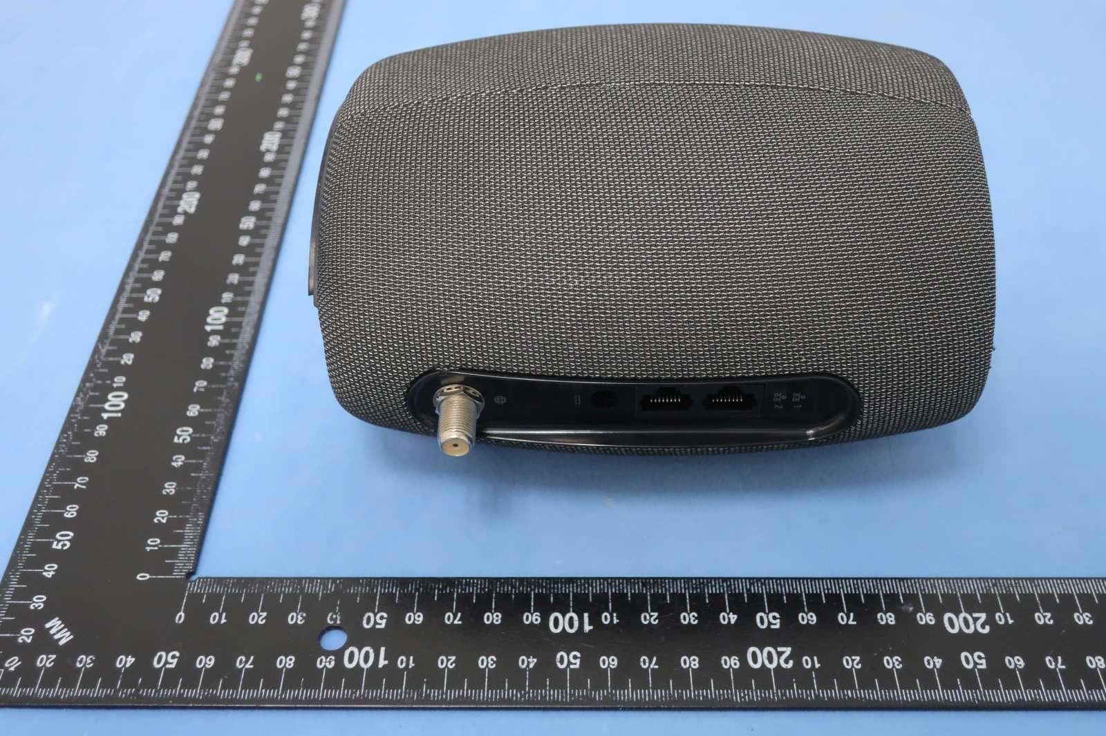
2AF5PG11
May 03, 2023D3.1 Cable Modem plus AX3000 Router
Equipment Class
DTS - Digital Transmission System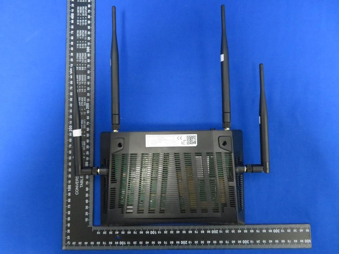
2AF5PR14
Apr 04, 2023AX6000 Dual-band WiFi Router
Equipment Class
NII - Unlicensed National Information Infrastructure TX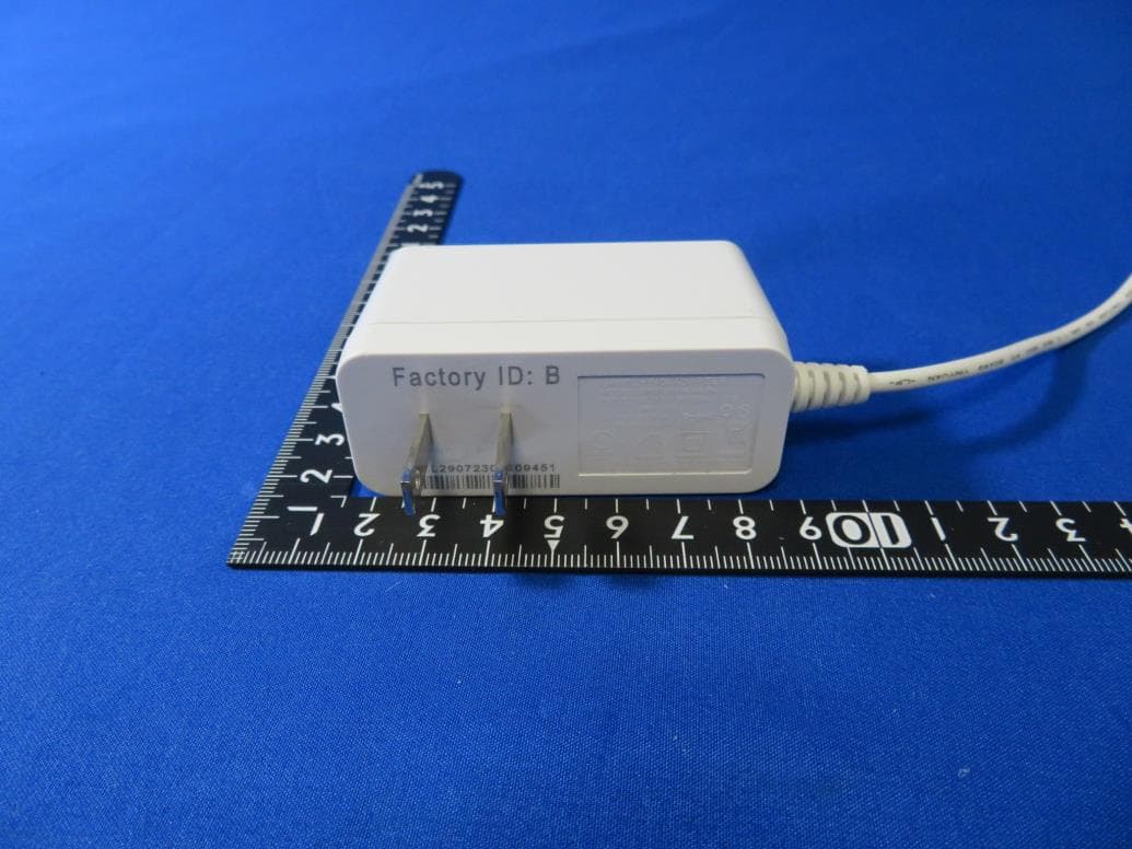
2AF5PMH7601
Aug 10, 2021AX1800 Dual-band Mesh WiFi
Equipment Class
DTS - Digital Transmission System
2AF5PMGMT87
Sep 20, 2020D3.1 Cable Modem plus AX6000 Router with Voice
Equipment Class
NII - Unlicensed National Information Infrastructure TX
2AF5PML2410
Apr 23, 2020AC1900 LTE Router
Equipment Class
NII - Unlicensed National Information Infrastructure TX