2AF5PMGMT87D3.1 Cable Modem plus AX6000 Router with Voice
MTRLC LLC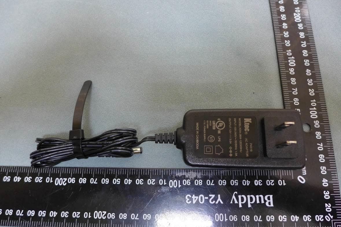
Click to zoom
Application Details
- Equipment Class
- NII - Unlicensed National Information Infrastructure TX
- Date of Grant
- Sep 20, 2020
- Application Purpose
- Original Equipment
- Date of Application
- Sep 07, 2020
- Equipment Note
- D3.1 Cable Modem plus AX6000 Router with Voice
- Frequency Range
- 5745.00000000 - 5825.00000000
- Company
- MTRLC LLC
- Country
- United States
Documents & Files
Document Text
Text extracted from the exhibit documents filed with the FCC. Open a document above to read the original.
Users Manual
Quick Start DOCSIS 3.1 Cable Modem plus AX6000 Router plus 2 Xfinity Phone Lines MODEL MT8733 1 Packaged with your MT8733 Power Supply Ethernet Cable RJ11 phone cord Coax Wrench Velcro ® Cable Organizer Para una Guía de Inicio Rápido en español, por favor vaya a www.motorolanetwork.com/MT8733ir 2 Let’s get started If you don’t have cable Internet service, please order that from your cable service provider. Comcast Xfinity customers should also order phone service if they want to use the MT8733 phone lines. This phone capability works for Xfinity, but not for most other cable services. If you already have an installed cable modem/router, simply disconnect your current modem and connect the MT8733, making sure to use the power supply provided with the MT8733. Reconnect the existing coax cable and any other appropriate cables as described on page 3. Then activate as described starting on page 4. Connect your MT8733 as shown on page 3. Connecting to a Coax Cable Please see the connection photo on the next panel. You connect your MT8733 to a “live” coax cable. Sometimes a cable will already be available. Sometimes there’s a coax wall jack available, and you connect to the jack with a coax cable. Your MT8733 can also share a coax cable attached to a TV by using a coax splitter. Please note that a badly chosen splitter reduces a cable modem's speed; so if you need to use a splitter, use a 2-way splitter whose top frequency is 1,000 MHz or higher. 3 PHONE (TEL1-2) If you have Xfinity phone service, you can connect telephones to Tel1 or to both of these phone jacks. ETHERNET (LAN 1-4) You can connect a computer, HDTV, game station, or other Ethernet-capable device to any of these 4 LAN ports. Note the 2.5GE port (2.5Gbps). COAX Connect a “live” coax cable to the modem’s COAX connector as discussed above. (Tighten the nut so it’s finger tight. You may want to use the supplied wrench. Make the connection snug but not over-tight.) POWER Connect the supplied power cube between the power jack and an electrical outlet. RESET WPS button Prepare to activate By now you should have: • Subscribed to cable Internet service, and possibly to Xfinity phone service. 4 • Connected your MT8733. • Powered up your cable modem/router. To do this, plug the power supply into a standard wall outlet, and plug the power connector into your MT8733. Wait for the green or blue online connection light to stop flashing and remain solidly lit. This may take up to 15 minutes. You may need your cable service account number for product registration. A recent cable bill/statement will have this information. If you’re asked for information about the MT8733, such as the Mac Address or Serial Number, you can find this on the label on the bottom of the modem/router. Activate Activate your MT8733 by opening the Web browser of a computer or other device that’s connected to your MT8733, and enter xfinity.com/activate. Your device can be connected either wirelessly or via one of the MT8733’s Ethernet ports. If you connect wirelessly, you’ll need the unique Wireless Network Name and Password printed on the bottom of your MT8733. (You may wish to write these down or take a picture. Later, you will be able to change your SSID and Password if you desire.) You’ll use these in setting up your wireless device to connect to the MT8733. Once you’ve connected, you can open the browser of that wireless device. Alternatively, call the Comcast Xfinity number: 1-800- XFINITY 5 Once your MT8733 is activated either online or by phone, your service provider will provision your MT8733 service. Typically this takes less than 5 minutes for Internet, but in some cases this may take 30 minutes or longer. If you activate voice service for the first time, your service provider may take several days to activate that service. Once you have been activated, try to browse the Web using a device connected via Ethernet or WiFi to the MT8733. (See the section Wireless Router below for information on connecting via WiFi). If browsing works, Congratulations! Your MT8733’s Internet capability is working. If you have Xfinity phone service and want to use that, make sure the MT8733’s Tel1 light is ON. (You may have to wait a few minutes after power-up.) If you haven’t already, plug a phone into the Tel1 port. Take the phone off-hook and confirm there is a dial tone. Then make a call and ask the person who answers to call you right back. Hang up so you can receive the incoming call and verify that your phone is working. For more information about using the MT711 telephone capability, please see the Telephone Adapter section on page 8. If your MT8733 is NOT working, see Troubleshooting Tips on page 12. Note on phone service: Xfinity offers phone service for one phone number only or for two phone numbers. Tel1 works with one line and will work with the optional UPS power backup device for 5 hours of talk time if AC power is lost (15 hours with additional booster packs). Tel2 will only work if you have 2 phone numbers from Xfinity. The second phone number will not work if AC power is lost. 6 Configuration Manager You may not need to use the MT8733’s Configuration Manager. Here are some reasons for using it: • You want to change the wireless network name and password. For instance, maybe you want a more easily remembered name, or you're replacing a router and want to use your existing WiFi Network Name (SSID) and/or WiFi Password/Key instead of the unique ones that come with the MT8733. You can use the same SSID and Password for both 5G and 2.4G. When connecting to WiFi, the MT8733 will connect using the best band available. • You want to set up special Internet gaming settings. • You want to get performance information about the MT8733 modem and/or built-in router. This can be helpful in diagnosing DOCSIS performance issues and/or optimizing wireless performance. If you need to access the MT8733 Configuration Manager, open your Web browser. Type http://192.168.0.1 in the address …
Text truncated - open the document above for the full version.
Cover Letter(s)
RF_160, Issue 04 MTRLC LLC Declaration of Authorization We N ame: MTRLC LLC Address: 225 Franklin Street, 26th Floor City: Boston State: Massachusetts Country: United States Zip Code: 02110 Dec lare that: Nam e Representative of agent: Ms. Melody Wu Agent Company name: BTL Inc. Address: 4F,No.18, Ln. 171, Sec. 2, Jiuzong Rd., Neihu Dist.114, City: Taipei Country Taiwan is authorized to apply for Certification of the following product(s ): Product description: D3.1 Cable Modem plus AX6000 Router with Voice Type designation: MT8733, MG8725 Trademark: Motorola Validity/ expiry date: From June 17, 2020 to June 16, 2021 on our behal f. Dat e: June 17, 2020 City : Boston Nam e: Andy Pollock Funct ion: Director of Engineering Si gnature: Notes: (1): Required for FCC application (2): For FCC it must be the Grantee Code “owner” or the authorized agent.
Cover Letter(s)
FCC, Request for non-disclosure Date: 21-Nov-2018 RF_501, Issue 8 Page 1 of 1 Company Name: MTRLC LLC Address : 225 Franklin St., 26 th Floor City: Boston, MA 02110 Country: USA To: Telefication B.V., Dept. FCC TCB Edisonstraat 12A 6902 PK ZEVENAAR The Netherlands Subject: Request for confidentiality FCC ID: 2AF5PMGMT87 Reference number: Dear FCC TCB, 1. Long-Term Confidentiality Pursuant to 47 CFR Section 0.459(a) & (b), we hereby request non-disclosure and confidential treatment of the following materials submitted in support of FCC certification application: Block Diagrams Operational Description Schematic Diagrams Above materials contain secrets, proprietary and technical information, which would customarily be guarded from competitors under 47 CFR, section 0.457(d)(2). Disclosure or publication or any portion of this company confidential material to other parties could cause substantial competitive harm and provide unjustified benefits for competitors. 2. Short-Term Confidentiality (STC) Pursuant to Public Notice DA 04-1705 of the Commission’s policy, in order to comply with the marketing regulations in 47 CFR §2.803 and the importation rules in 47 CFR §2.1204, a pplicant hereby requests Short-Term Confidential treatment of the following materials (See notes below): Internal Photos User’s Manual Test Set-up Photos External Photos Justification: This document contains detailed system and equipment description are considered as proprietary information in operation of the equipment. The public disclosure of above documents might be harmful to our company and would give competitor unfair advantage in the market. Date: 2020-09-02 Name and signature of applicant: Andy Pollock Notes: 1) A document or type of document can only have ONE type of confidentiality! 2) Short-Term confidentiality is in principle for 45 days from date of grant; it can be extended max 3 times (total time 180 days max.)! The planned date should stated in the RF731 application form. 3) FCC must be informed when marketing begins earlier. 4) Release takes place automatically thus extension must be requested in time. Telefication does not remind you of this! 5) Request for extension or for release must be received by Telefication at least 7 days before date of actual marketing or before expiration of the STC period
Cover Letter(s)
MTRLC LLC Ad Hoc Mode Declaration Date: 2020-06-17 We, the undersigned company Company Name: MTRLC LLC Address: 225 Franklin Street, 26th Floor, Boston, Massachusetts 02110, United States Declare that: Product description: D3.1 Cable Modem plus AX6000 Router with Voice Type designation: MT8733, MG8725 Brand: Motorola FCC ID: 2AF5PMGMT87 1. The EUT doesn’t have Ad Hoc Mode function on “non-US frequencies”. 802.11a/n Ad Hoc mode should not be supported even on US DFS frequencies (5.25 ~5.35GHz/5.47 ~5.725GHz). 2. In addition, the frequency selection feature is disabled by firmware for devices marketed to the US. The product meets all other requirements specified in Part 15E Section 15.407 and no configuration controls are provided to change the frequency of operations outside the grant of certification for US operation. 3. O nly channels 1~11 will be used in USA. Country code selection is disabled. I f you have any questions regarding the authorization, please do not hesitate to contact us, thank you~ S incerely, Signature: ________________________ Name: Andy Pollock Tel: 617-753-0663 or 617-753-3086 Email: [email protected]
Cover Letter(s)
Date : July 3, 2020 UNII Declaration Letter We have declared below featured for FCC equipment authorization, Device FCC ID: 2AF5PMGMT87 DFS Device -- Master , Client with Radar detection capability Client without radar detection capability Active / Passive Scanning , Ad hoc mode access point capability Frequency Band (MHz) Active Scanning (the device can transmit a probe (beacon)) passive scanning (where the device is can listen only with no probes) Ad Hoc Mode capability Access point capability 5150 – 5250 Yes , No Yes , No Yes , No Yes , No 5250 – 5350 Yes , No Yes , No Yes , No Yes , No 5470 – 5725 Yes , No Yes , No Yes , No Yes , No 5725 – 5850 Yes , No Yes , No Yes , No Yes , No Country code selection ability - Yes , No If yes, pls explain how it was implemented: (pls also help to provide detail of options for each country selection) : Meet 15.202 requirement - Yes , No , pls check below : A master device is defined as a device operating in a mode in which it has the capability to transmit without receiving an enabling signal. In this mode it is able to select a channel and initiate a network by sending enabling signals to other devices. A client device is defined as a device operating in a mode in which the transmissions of the device are under control of the master. A device in client mode is not able to initiate a network. Applicant : MTRLC LLC Address : 225 Franklin St. 26th Floor, Boston, MA 02110 Signature : _________________________________ Name and Job Title. : Andy Pollock/ Director of Engineering
Cover Letter(s)
MTRLC LLC Declaration Letter Date: 2020-06-17 We, the undersigned company Company Name: MTRLC LLC Address: 225 Franklin Street, 26th Floor, Boston, Massachusetts 02110, United States Declare that: Product description: D3.1 Cable Modem plus AX6000 Router with Voice Type designation: MT8733, MG8725 Brand: Motorola FCC ID: 2AF5PMGMT87 this device with Bridge and Mesh modes of operation are permitted to operate in the DFS band and employ a DFS function. The functionality of the Bridge mode as specified in §15.403(a) and the Mesh mode is validated in the DFS test report by performing a test statistical performance check on any one of the radar types. If you have any questions regarding the authorization, please do not hesitate to contact us, thank you~ Sincerely, Signature: ________________________ Name: Andy Pollock Tel: 617-753-0663, or 617-753-3086 Email: [email protected]
External Photos
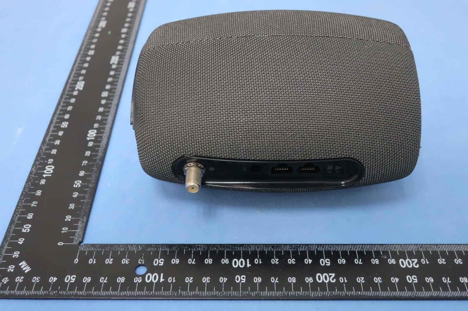
Appendix No.: EP-2006T060-1 APPENDIX-EUT PHOTOS Project No.: 2006T060 Page 1 of 50 MT-8733 Appendix No.: EP-2006T060-1 APPENDIX-EUT PHOTOS Project No.: 2006T060 Page 2 of 50 Appendix No.: EP-2006T060-1 APPENDIX-EUT PHOTOS Project No.: 2006T060 Page 3 of 50 Appendix No.: EP-2006T060-1 APPENDIX-EUT PHOTOS Project No.: 2006T060 Page 4 of 50 Appendix No.: EP-2006T060-1 APPENDIX-EUT PHOTOS Project No.: 2006T060 Page 5 of 50 Appendix No.: EP-2006T060-1 APPENDIX-EUT PHOTOS Project No.: 2006T060 Page 6 of 50 MG-8725 Appendix No.: EP-2006T060-1 APPENDIX-EUT PHOTOS Project No.: 2006T060 Page 7 of 50 Appendix No.: EP-2006T060-1 APPENDIX-EUT PHOTOS Project No.: 2006T060 Page 8 of 50 Appendix No.: EP-2006T060-1 APPENDIX-EUT PHOTOS Project No.: 2006T060 Page 9 of 50 Appendix No.: EP-2006T060-1 APPENDIX-EUT PHOTOS Project No.: 2006T060 Page 10 of 50 Appendix No.: EP-2006T060-1 APPENDIX-EUT PHOTOS Project No.: 2006T060 Page 11 of 50 Adapter: ADS-40FSI-12 Appendix No.: EP-2006T060-1 APPENDIX-EUT PHOTOS Project No.: 2006T060 Page 12 of 50 Appendix No.: EP-2006T060-1 APPENDIX-EUT PHOTOS Project No.: 2006T060 Page 13 of 50 Appendix No.: EP-2006T060-1 APPENDIX-EUT PHOTOS Project No.: 2006T060 Page 14 of 50 Adapter: KSA-36W-120300H Appendix No.: EP-2006T060-1 APPENDIX-EUT PHOTOS Project No.: 2006T060 Page 15 of 50 Appendix No.: EP-2006T060-1 APPENDIX-EUT PHOTOS Project No.: 2006T060 Page 16 of 50
ID Label/Location Info
Notes: 1) Material : Black Text on White Polyester or equivalent with Permanent adhesive 2) All dimensions are in mm 3) The serial number will be of the Format DDDY-MT8733-BB-#### where: DDD = the Julian date of the day manufacture. Example January 1 is 001, Feb 1 is 032, December 31 = 365. Tolerance = +/- 3 days Y= the significant digit of the Year of manufacture. Example 2010 = 0, 2011=1, 2017=7. MT8733= the exact Model Number of the Product, printed as shown. BB = country of origin (location of manufacture), 10=China, 30=Vietnam, 40=Taiwan #### = a sequential number from 0001 to 9999 that indicates the number of the unit produced of that type, on that day. 4) Printing and material must meet UL Rub Test requirements 5) SSID to be MOTOSSSS where SSSS is the last 4 digits of the CM MAC. 5a) MTA MAC address shall be CM MAC + 1 6) The password "word1word2nnn" (in two locations that match) is constructed as a randomly chosen word from the “ZoomWiFiWords.xlsx” file’s adjective column (word1), a randomly chosen word from the noun column (word2), and a randomly selected 3-digit number “nnn” that cannot contain a 0 or a 1 (must use only digits 2,3,4,5,6,7,8,9). For example, “plasticbarn352”. 7) XXXX is to be the 4-letter Factory ID for the product as specified by Bureau Veritas (pending) 8) CCCCCCC is to be the Country of Origin, use “China” for product manufactured in China, or use “Vietnam” for product manufactured in Vietnam. 9) The Part Number (P/N) shall be of the form MT8733-BB, where BB=country of origin (location of manufacture), 10=China, 30=Vietnam, 40=Taiwan 10) All fonts, sizes, styles, spacing, alignment, positioning, locations, logos and line thicknesses are to be exactly as shown and as embedded in this document, except for the outside border line which is shown for reference only, and is not to be printed. 11) Add QR code image in location as shown by example below, size 25mmx25mm. QR code content to be as follows: WIFI:T:WPA2;S:MOTOSSSS;P:word1word2nnn;;DEVICE:M:MMMMMMMMSSSS;S:DDDY‐MT8733‐BB‐ ####;T:MT8733;; Where above text in red is static, always included exactly as shown. The above text in blue is variable and shall be as described in the above notes 3, 5, 6 and 9. 12) A clear, high-resolution image of a printed sample of the label must be provided for approval 13) see label dimensions on page 2 WiFi Network Name (SSID): MOTOSSSS WiFi Password: word1word2nnn D3.1 Cable Modem plus AX6000 Router with Voice Model: MT8733 motorolanetwork.com MTRLC LLC S/N: DDDY-MT8733-BB-#### CM MAC: ZZZZZZZZSSSS MTA MAC: ZZZZZZZZZZZZ Configuration Manager IP Address: 192.168.0.1 Username: admin Password: word1word2nnn Made in CCCCCCC FCC ID: 2AF5PMGMT87 P/N: MT8733-BB Power: +12VDC 3A Zoom Telephonics Inc 225 Franklin Street, Boston MA 02110 USA PROPRIETARY AND CONFIDENTIAL THE INFORMATION CONTAINED IN THIS DRAWING IS THE SOLE PROPERTY OF Zoom Telephonics, Inc. ANY REPRODUCTION IN PART OR AS A WHOLE WITHOUT THE WRITTEN PERMISSION OF Zoom Telephonics, Inc IS PROHIBITED. TITLE: Compliance Label, MT8733 Production Version UNLESS OTHERWISE SPECIFIED: XXXX SIZE A NAME DATE DRAWN CHECKED ENG APPR. MFG APPR. Q.A. COMMENTS: DWG. NO. 36461-1 REV C1 SCALE 1:1 WEIGHT: SHEET 1 OF 1 DIMENSIONS ARE IN MM TOLERANCES: FRACTIONAL +/‐ ANGULAR: MACH +/‐ BEND +/‐ TWO PLACE DECIMAL +/‐ THREE PLACE DECIMAL +/‐ INTERPRET GEOMETRIC TOLERANCING PER: MATERIAL: FINISH: DO NOT SCALE DRAWING This device complies with Part 15 of the FCC Rules and Industry Canada requirements. USED ON Operation is subject to the following two conditions:(1)This device may not cause harmful interference, and (2) this device must accept any interference received, including interference that may cause undesired operation. This Class B digital apparatus complies with Canadian ICES-003. Cet apparéil numérique de la class B est conforme à la norme NMB-003 du Canada. APPLICATION NEXT ASSY SIZE A DWG. NO. 36461-1 REV C1 SCALE 1:1 WEIGHT: SHEET 2 OF 2 Notes: 1) Material : Black Text on White Polyester or equivalent with Permanent adhesive 2) All dimensions are in mm 3) The serial number will be of the Format DDDY-MG8725-BB-#### where: DDD = the Julian date of the day manufacture. Example January 1 is 001, Feb 1 is 032, December 31 = 365. Tolerance = +/- 3 days Y= the significant digit of the Year of manufacture. Example 2010 = 0, 2011=1, 2017=7. MG8725= the exact Model Number of the Product, printed as shown. BB = country of origin (location of manufacture), 10=China, 30=Vietnam, 40=Taiwan #### = a sequential number from 0001 to 9999 that indicates the number of the unit produced of that type, on that day. 4) Printing and material must meet UL Rub Test requirements 5) SSID to be MOTOSSSS where SSSS is the last 4 digits of the CM MAC. 6) The password "word1word2nnn" (in two locations that match) is constructed as a randomly chosen word from the “ZoomWiFiWords.xlsx” file’s adjective column (word1), a randomly chosen word from the noun column (word2), and a randomly selected 3-digit number “nnn” that cannot contain a 0 or a 1 (must use only digits 2,3,4,5,6,7,8,9). For example, “plasticbarn352”. 7) XXXX is to be the 4-letter Factory ID for the product as specified by Bureau Veritas (pending) 8) CCCCCCC is to be the Country of Origin, use “China” for product manufactured in China, or use “Vietnam” for product manufactured in Vietnam. 9) The Part Number (P/N) shall be of the form MG8725-BB, where BB=country of origin (location of manufacture), 10=China, 30=Vietnam, 40=Taiwan 10) All fonts, sizes, styles, spacing, alignment, positioning, locations, logos and line thicknesses are to be exactly as shown and as embedded in this document, except for the outside border line which is shown for reference only, and is not to be printed. 11) Add QR code image in location as shown by example below, size 25mmx25mm. QR code content to be as follows: WIFI:T:WPA2;S:MOTOSSSS;P:word1word2nnn;;DEVICE:M:MMMMMMMMSSSS;S:DDDY‐MG8725‐BB‐ ####;T:MG8725;; Where above text in red…
Text truncated - open the document above for the full version.
Internal Photos
Appendix No.: EP-2006T060-1 APPENDIX-EUT PHOTOS Project No.: 2006T060 Page 17 of 50 MT-8733 Appendix No.: EP-2006T060-1 APPENDIX-EUT PHOTOS Project No.: 2006T060 Page 18 of 50 Appendix No.: EP-2006T060-1 APPENDIX-EUT PHOTOS Project No.: 2006T060 Page 19 of 50 Appendix No.: EP-2006T060-1 APPENDIX-EUT PHOTOS Project No.: 2006T060 Page 20 of 50 Appendix No.: EP-2006T060-1 APPENDIX-EUT PHOTOS Project No.: 2006T060 Page 21 of 50 Appendix No.: EP-2006T060-1 APPENDIX-EUT PHOTOS Project No.: 2006T060 Page 22 of 50 Appendix No.: EP-2006T060-1 APPENDIX-EUT PHOTOS Project No.: 2006T060 Page 23 of 50 Appendix No.: EP-2006T060-1 APPENDIX-EUT PHOTOS Project No.: 2006T060 Page 24 of 50 Appendix No.: EP-2006T060-1 APPENDIX-EUT PHOTOS Project No.: 2006T060 Page 25 of 50 Appendix No.: EP-2006T060-1 APPENDIX-EUT PHOTOS Project No.: 2006T060 Page 26 of 50 Appendix No.: EP-2006T060-1 APPENDIX-EUT PHOTOS Project No.: 2006T060 Page 27 of 50 Appendix No.: EP-2006T060-1 APPENDIX-EUT PHOTOS Project No.: 2006T060 Page 28 of 50 Appendix No.: EP-2006T060-1 APPENDIX-EUT PHOTOS Project No.: 2006T060 Page 29 of 50 Appendix No.: EP-2006T060-1 APPENDIX-EUT PHOTOS Project No.: 2006T060 Page 30 of 50 Appendix No.: EP-2006T060-1 APPENDIX-EUT PHOTOS Project No.: 2006T060 Page 31 of 50 Appendix No.: EP-2006T060-1 APPENDIX-EUT PHOTOS Project No.: 2006T060 Page 32 of 50 Appendix No.: EP-2006T060-1 APPENDIX-EUT PHOTOS Project No.: 2006T060 Page 33 of 50 MG-8725 Appendix No.: EP-2006T060-1 APPENDIX-EUT PHOTOS Project No.: 2006T060 Page 34 of 50 Appendix No.: EP-2006T060-1 APPENDIX-EUT PHOTOS Project No.: 2006T060 Page 35 of 50 Appendix No.: EP-2006T060-1 APPENDIX-EUT PHOTOS Project No.: 2006T060 Page 36 of 50 Appendix No.: EP-2006T060-1 APPENDIX-EUT PHOTOS Project No.: 2006T060 Page 37 of 50 Appendix No.: EP-2006T060-1 APPENDIX-EUT PHOTOS Project No.: 2006T060 Page 38 of 50 Appendix No.: EP-2006T060-1 APPENDIX-EUT PHOTOS Project No.: 2006T060 Page 39 of 50 Appendix No.: EP-2006T060-1 APPENDIX-EUT PHOTOS Project No.: 2006T060 Page 40 of 50 Appendix No.: EP-2006T060-1 APPENDIX-EUT PHOTOS Project No.: 2006T060 Page 41 of 50 Appendix No.: EP-2006T060-1 APPENDIX-EUT PHOTOS Project No.: 2006T060 Page 42 of 50 Appendix No.: EP-2006T060-1 APPENDIX-EUT PHOTOS Project No.: 2006T060 Page 43 of 50
Internal Photos
Appendix No.: EP-2006T060-1 APPENDIX-EUT PHOTOS Project No.: 2006T060 Page 44 of 50 Appendix No.: EP-2006T060-1 APPENDIX-EUT PHOTOS Project No.: 2006T060 Page 45 of 50 Appendix No.: EP-2006T060-1 APPENDIX-EUT PHOTOS Project No.: 2006T060 Page 46 of 50 Appendix No.: EP-2006T060-1 APPENDIX-EUT PHOTOS Project No.: 2006T060 Page 47 of 50 Appendix No.: EP-2006T060-1 APPENDIX-EUT PHOTOS Project No.: 2006T060 Page 48 of 50 Appendix No.: EP-2006T060-1 APPENDIX-EUT PHOTOS Project No.: 2006T060 Page 49 of 50 Appendix No.: EP-2006T060-1 APPENDIX-EUT PHOTOS Project No.: 2006T060 Page 50 of 50
RF Exposure Info
Report No.: BTL-FCCP-7-2006T060 Project No.: 2006T060 Page 1 of 4 Report Version: R00 Maximum Permissible Exposure Report FCC ID: 2AF5PMGMT87 Report No. : BTL-FCCP-7-2006T060 Equipment : D3.1 Cable Modem plus AX6000 Router with Voice Model Name : MT8733, MG8725 Brand Name : MOTOROLA Applicant : MTRLC LLC Address : 225 Franklin Street, 26th Floor, Boston, MA 02110 USA FCC Rule Part(s) : FCC Guidelines for Human Exposure IEEE C95.1 Date of Receipt : 2020/6/12 Date of Test : 2020/6/12 ~ 2020/8/11 Issued Date : 2020/8/26 The above equipment has been tested and found in compliance with the requirement of the above standards by BTL Inc. Prepared by : Peter Chen, Engineer Approved by : Scott Hsu, Manager BTL Inc. No.18, Ln. 171, Sec. 2, Jiuzong Rd., Neihu Dist., Taipei City 114, Taiwan Tel: +886-2-2657-3299 Fax: +886-2-2657-3331 Web: www.newbtl.com Report No.: BTL-FCCP-7-2006T060 Project No.: 2006T060 Page 2 of 4 Report Version: R00 REPORT ISSUED HISTORY Report Version Description Issued Date R00 Original Issue. 2020/8/26 Report No.: BTL-FCCP-7-2006T060 Project No.: 2006T060 Page 3 of 4 Report Version: R00 Table for Filed Antenna For Z-Wave: Ant. Model No. Antenna Type Connector Gain (dBi) 1 Metal PIFA SMA 0 For Zigbee, BLE: Ant. Model No. Antenna Type Connector Gain (dBi) 1 Metal PIFA SMA 3 For2.4GHz WLAN: Ant. Model No. Antenna Type Connector Gain (dBi) 1 PCB Dipole SMA 3 2 PCB Dipole SMA 3 3 PCB Dipole SMA 3 4 PCB Dipole SMA 3 For 5GHz RLAN: Ant. Model No. Antenna Type Connector Gain (dBi) 1 PCB Dipole SMA 4 2 PCB Dipole SMA 4 3 PCB Dipole SMA 4 4 PCB Dipole SMA 4 MPE CALCULATION METHOD: Calculation Method of RF Safety Distance: where: S = power density P = power input to the antenna G = power gain of the antenna in the direction of interest relative to an isotropic radiator R = distance to the center of radiation of the antenna Report No.: BTL-FCCP-7-2006T060 Project No.: 2006T060 Page 4 of 4 Report Version: R00 TEST RESULTS For Z-Wave: Antenna Gain (dBi) Antenna Gain (numeric) Max. Output Power (dBm) Max. Output Power ( mW ) Power Density (S) (mW/cm2) Limit of Power Density (S) (mW/cm2) Test Result 0.00 1.0000 11.00 12.5893 0.00250582 1 Complies For Zigbee: Antenna Gain (dBi) Antenna Gain (numeric) Max. Output Power (dBm) Max. Output Power ( mW ) Power Density (S) (mW/cm2) Limit of Power Density (S) (mW/cm2) Test Result 3.00 1.9953 16.88 48.7528 0.01936201 1 Complies For BLE: Antenna Gain (dBi) Antenna Gain (numeric) Max. Output Power (dBm) Max. Output Power ( mW ) Power Density (S) (mW/cm2) Limit of Power Density (S) (mW/cm2) Test Result 3.00 1.9953 18.15 65.3131 0.02593883 1 Complies For 2.4G WLAN: Antenna Gain (dBi) Antenna Gain (numeric) Max. Output Power (dBm) Max. Output Power ( mW ) Power Density (S) (mW/cm2) Limit of Power Density (S) (mW/cm2) Test Result 3.00 1.9953 29.91 979.4900 0.38900069 1 Complies For 5G RLAN: Antenna Gain (dBi) Antenna Gain (numeric) Max. Output Power (dBm) Max. Output Power ( mW ) Power Density (S) (mW/cm2) Limit of Power Density (S) (mW/cm2) Test Result 4.002.511929.97993.11600.496535571Complies Note: 1. The calculated distance is 20 cm. End of Test Report
Test Report
Report No.: BTL-FCCP-5-2006T060 Project No.: 2006T060 Page 1 of 769 Report Version: R02 FCC Radio Test Report FCC ID: 2AF5PMGMT87 Report No. : BTL-FCCP-5-2006T060 Equipment : D3.1 Cable Modem plus AX6000 Router with Voice Model Name : MT8733, MG8725 Brand Name : MOTOROLA Applicant : MTRLC LLC Address : 225 Franklin Street, 26th Floor, Boston, MA 02110 USA Radio Function : RLAN 5 GHz (U-NII 1, U-NII 2A, U-NII 2C, U-NII 3) FCC Rule Part(s) : FCC Part15, Subpart E (15.407) Measurement Procedure(s) : ANSI C63.10-2013 Date of Receipt : 2020/6/12 Date of Test : 2020/6/12 ~ 2020/8/11 Issued Date : 2020/9/4 The above equipment has been tested and found in compliance with the requirement of the above standards by BTL Inc. Prepared by : Peter Chen, Engineer Approved by : Scott Hsu , Manager BTL Inc. No.18, Ln. 171, Sec. 2, Jiuzong Rd., Neihu Dist., Taipei City 114, Taiwan Tel: +886-2-2657-3299 Fax: +886-2-2657-3331 Web: www.newbtl.com Report No.: BTL-FCCP-5-2006T060 Project No.: 2006T060 Page 2 of 769 Report Version: R02 Declaration BTL represents to the client that testing is done in accordance with standard procedures as applicable and that test instruments used has been calibrated with standards traceable to international standard(s) and/or national standard(s). BTL's reports apply only to the specific samples tested under conditions. It is manufacture’s responsibility to ensure that additional production units of this model are manufactured with the identical electrical and mechanical components. BTL shall have no liability for any declarations, inferences or generalizations drawn by the client or others from BTL issued reports. The report must not be used by the client to claim product certification, approval, or endorsement by NIST, A2LA, or any agency of the U.S. Government. This report is the confidential property of the client. As a mutual protection to the clients, the public and ourselves, the test report shall not be reproduced, except in full, without our written approval. BTL’s laboratory quality assurance procedures are in compliance with the ISO/IEC 17025 requirements, and accredited by the conformity assessment authorities listed in this test report. BTL is not responsible for the sampling stage, so the results only apply to the sample as received. The information, data and test plan are provided by manufacturer which may affect the validity of results, so it is manufacturer’s responsibility to ensure that the apparatus meets the essential requirements of applied standards and in all the possible configurations as representative of its intended use. Limitation For the use of the authority's logo is limited unless the Test Standard(s)/Scope(s)/Item(s) mentioned in this test report is (are) included in the conformity assessment authorities acceptance respective. Please note that the measurement uncertainty is provided for informational purpose only and are not use in determining the Pass/Fail results. Report No.: BTL-FCCP-5-2006T060 Project No.: 2006T060 Page 3 of 769 Report Version: R02 CONTENTS REPORT ISSUED HISTORY 5 1 SUMMARY OF TEST RESULTS 6 1.1 TEST FACILITY 7 1.2 MEASUREMENT UNCERTAINTY 7 1.3 TEST ENVIRONMENT CONDITIONS 7 1.4 TABLE OF PARAMETERS OF TEST SOFTWARE SETTING 8 1.5 DUTY CYCLE 12 2 GENERAL INFORMATION 15 2.1 DESCRIPTION OF EUT 15 2.2 TEST MODES 20 2.3 BLOCK DIAGRAM SHOWING THE CONFIGURATION OF SYSTEM TESTED 22 2.4 SUPPORT UNITS 22 3 AC POWER LINE CONDUCTED EMISSIONS TEST 23 3.1 LIMIT 23 3.2 TEST PROCEDURE 23 3.3 DEVIATION FROM TEST STANDARD 23 3.4 TEST SETUP 24 3.5 TEST RESULT 24 4 RADIATED EMISSIONS TEST 25 4.1 LIMIT 25 4.2 TEST PROCEDURE 26 4.3 DEVIATION FROM TEST STANDARD 26 4.4 TEST SETUP 27 4.5 EUT OPERATING CONDITIONS 28 4.6 TEST RESULT – 30 MHZ TO 1 GHZ 28 4.7 TEST RESULT – ABOVE 1 GHZ 28 5 BANDWIDTH TEST 29 5.1 LIMIT 29 5.2 TEST PROCEDURE 29 5.3 DEVI…
Text truncated - open the document above for the full version.
Contact Information
Applicant
Andrew Pollock
Technical Contact
BTL Inc.Scott Hsu
[email protected]+886-2-26418198
No. 18, Ln. 171, Sec. 2, Jiuzong Rd., · Taipei · Taiwan
Non-Technical Contact
BTL Inc.Melody Wu
[email protected]+886-2-26418198
Test Firm
BTL Inc.Jackie Chiu
Technical Specifications
| # | Rule Parts | Frequency Range | Power Output |
|---|---|---|---|
| 4 | 15E | 5.75 GHz - 5.83 GHz | 992.70 mW |
Other Applications from MTRLC LLC
2AF5PG11
May 03, 2023D3.1 Cable Modem plus AX3000 Router
Equipment Class
DTS - Digital Transmission System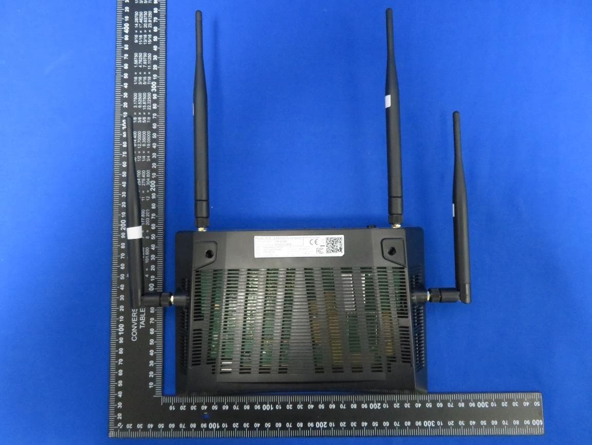
2AF5PR14
Apr 04, 2023AX6000 Dual-band WiFi Router
Equipment Class
NII - Unlicensed National Information Infrastructure TX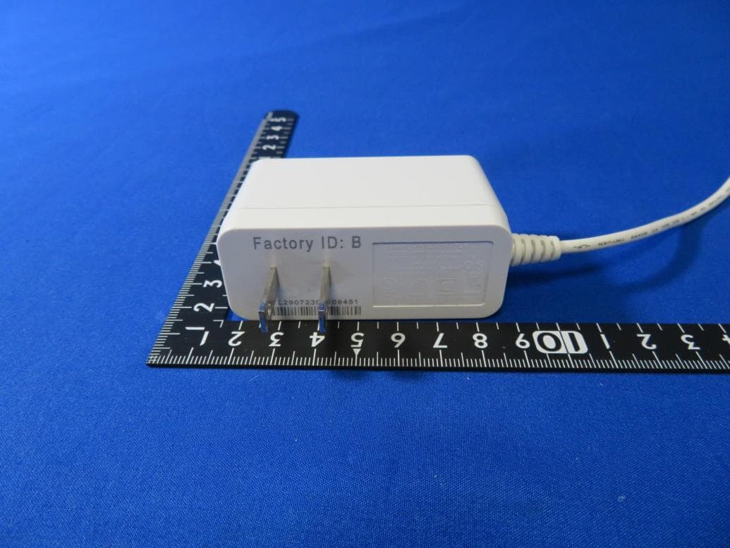
2AF5PMH7601
Aug 10, 2021AX1800 Dual-band Mesh WiFi
Equipment Class
DTS - Digital Transmission System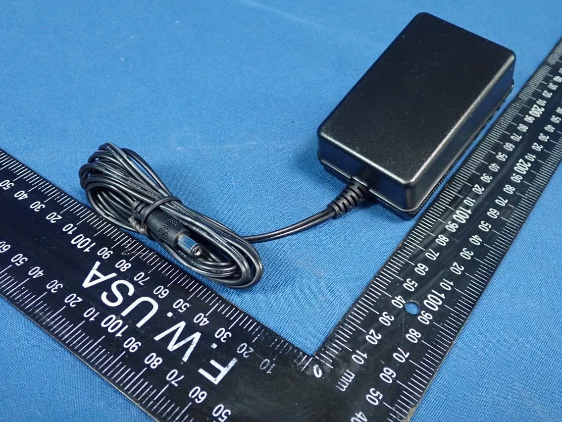
2AF5PML2410
Apr 23, 2020AC1900 LTE Router
Equipment Class
NII - Unlicensed National Information Infrastructure TX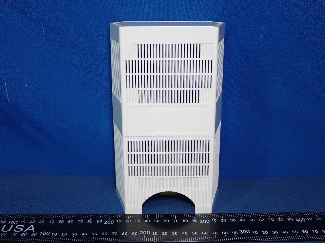
2AF5PMH7021
Mar 26, 2020AC2200 Tri-band Mesh WiFi
Equipment Class
DTS - Digital Transmission System