2AF5PML2410AC1900 LTE Router
MTRLC LLC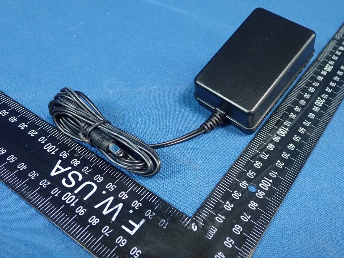
Click to zoom
Application Details
- Equipment Class
- NII - Unlicensed National Information Infrastructure TX
- Date of Grant
- Apr 23, 2020
- Application Purpose
- Original Equipment
- Date of Application
- Apr 16, 2020
- Equipment Note
- AC1900 LTE Router
- Frequency Range
- 5500.00000000 - 5720.00000000
- Company
- MTRLC LLC
- Country
- United States
Documents & Files
Document Text
Text extracted from the exhibit documents filed with the FCC. Open a document above to read the original.
Users Manual
AC1900 LTE Router Quick Start Model ML2410 Let’s get started If you want to provide cellular backup to your existing Internet connection we recommend setting up and testing the cellular connection as described below than changing the configuration to enable cellular backup. To use your ML2410 modem you need an activated micro SIM (3FF format), which you normally get from your mobile broadband service provider. If instead you use a nano SIM card (used by most phones today), you must use a SIM Card Adapter. SIM card adapters are available from Amazon and other online retailers. You must remove the battery cover on the ML2410’s back panel to access the SIM slot. Using a Philips head screwdriver remove the screw from the battery cover, remove the battery cover, and insert the SIM. Replace the battery cover when finished. Next, attach the 2 LTE Antennas to the ML2410 by screwing them finger- tight into the 2 gold connectors located on the back of the unit. Now, connect the supplied power cube between the ML2410’s power jack and a working electrical outlet. The ML2410 should power up and the power light on the top of the unit should turn amber while the unit powers up. If the power light does not turn on, check that the On/Off button on the back panel is On. Wait for the Cell Status light to turn on. This may take up to 2 minutes. If the Cell Status light does not turn on please see troubleshooting tips at the end of this Quick Start. If you want to use the ML2410 as cellular backup continue below, otherwise skip ahead to Connect your Devices below. Using the ML2410 for Cellular Backup Connect the ML2410’s yellow Ethernet cable between the ML2410’s WAN port and the Ethernet port of a cable modem, DSL modem, or fiber optic modem used for Internet access. Switch the power of the modem off now. (For some modem/routers, this requires you to remove a power backup battery.) After the modem is off for at least 10 seconds, switch it back on. (If you removed a backup battery, plug the battery back in first.) Now, connect the supplied power cube between the ML2410’s power jack and a working electrical outlet. The ML2410 should power up and the power light on the top of the unit should turn amber while the unit powers up. If the power light does not turn on, check that the On/Off button on the back panel is On. The power light will turn green when the unit has finished powering up. To configure your ML2410 for cellular backup you will need to access the ML2410’s configuration manager. To access the ML2410 with a wired connection plug an Ethernet cable into one of the ML2410’s LAN jacks and the other into your desktop or laptop’s Ethernet port. To connect via WiFi to the ML2410, go into the WiFi setup section for the device (not the router). Then use the ML2410 router’s WiFi Network Name (SSID) and WiFi Password/Key. The unique factory-set default settings are printed on a label on the bottom of the ML2410. Next, to access the ML2410’s configuration manager open your Web browser. Type http://192.168.5.1 in the address bar and press Enter. In the login dialog box, enter the Login information printed on the bottom label of your ML2410. The Basic Setup page will appear. If the Basic Setup page doesn’t appear, please see the Troubleshooting Tips below. From the dropdown menu next to Internet Connection, select the type of connection you have. Most users should select DHCP. Next check the box next to Enable Cellular Backup. This will turn on cellular backup in case your Internet connections goes down. The ML2410 should automatically detect your SIM card and should be configured correctly. Connect Your Devices The ML2410 lets many devices share your Internet connection. Devices can connect by using WiFi or by plugging into one of the ML2410 Ethernet ports. WiFi Wireless You can connect any of your WiFi devices by first going into the WiFi setup section for the device (not the router). Then use the ML2410 router’s WiFi Network Name (SSID) and WiFi Password/Key. The unique factory-set default settings are printed on a label on the bottom of the ML2410. If you prefer to use a different network name and password, please see the chapter. Changing Wireless Security Settings in the full length manual at www.motorolanetwork.com/ML2410manual Wired Ethernet You can also connect up to two HDTVs, computers, game stations, or other devices with an Ethernet cable between an Ethernet port of the device and any one of the LAN jacks on the router. Some devices have a Network Setup section where you specify a wired Ethernet connection. If you have a problem with a particular device, consult its user manual. Once you’ve set up a Wireless or Wired Ethernet connection, try to browse the Web. If browsing works, Congratulations! Your ML2410 is working. If your ML2410 is NOT working, see Troubleshooting Tips and We like to help at the end of this Quick Start. USB 3.0 Port Also available on the rear panel is a High-speed USB 3.0 port for connecting USB memory devices or external hard drives. This port can be used to attach USB Drives, that can then be accessed through the network. For more information on this feature go to www.motorolanetwork.com/ML2410manual . A cable for this port is not provided with the ML2410. Use a standard USB 3.0 cable to connect USB 3.0 devices, or a USB 2.0 cable can be used for USB 2.0 devices. For the ML2410-side of the connection, the cable needs to have a USB type-A male connector. MotoManage™ We strongly suggest that you download the MotoManage™ App from the Apple App Store or from Google Play to access basic and advanced network control features. The app lets you manage your network quickly and easily, and it makes it easy to keep your network’s original wireless settings The app includes basic and advanced features, which are all available free of charge for the first month. After that you will be able to decide whether you’d like to just keep the free features, or whether you’d like to also keep the a…
Text truncated - open the document above for the full version.
Cover Letter(s)
tT* icq sr'. 0<s LLC *zrts Zoom Telephonics and MTRLC LLC are authorized /icensees of the Motorola trademark. Confidentialit equest Date: March 3,2O2O Federal Communications Commission Authorization and Evaluation Dtivision X'CC ID: 2AF5PML2410 To Whom It May Concern, Long Term Confidentialit_v Pursuant to Sections 0.457 and 0.459 of the Commission's Rules, we hereby respectfully request confidential treatment of information accompanying this application as outlined below: Schematics Block Diagram Operational Descriptions Software Operating Descriptiron The above materials contain trarCe secrets and proprietary information not customarily released to the public. The public disclosure of'these matters might be harmful to the Applic and provide unjustified benefits to its competitors. We understand that pursuant to Rule 0.457, disclosure of this Application and all accompanying documentation will not be made before the date of the Grant for this application. Short Term Confidentiality Pursuant to Sections 0.457 and t0.459 of the Commission's Rules, we hereby respectfully request short-term confidential treatment of inforrnation accompanying this application as outlined below until 180 days after the Grant Date of Equipment Authorization in order to ensure sensitive business information remains confidential until the actual marketins of the, device: External Photos Internal Photos Test Setup Photos User Manual Andy Pollock / Director MTRLC LLC 225 Frunklin Street, 26th Floor, Boston, MA 021 10 USA Tel:617-753-0663 Email: [email protected] Hardwarengineering
Cover Letter(s)
22,* ff&r'*# 0x.1ts Zoom Telephonics and MTRLC LLC are authorized /lcensees of the Motorola trade,mark. Date: March3,2020 FCC lD: 2AF5PML2410 To whom it may concern: MTRLC LLC. hereby authorizes Debby Lin/ Senior Specialist of Bureau Veritas Consumer products Services (H.K.) Ltd., Taoyuan Branch ("BV cPs Taoyuan"), to act on its behalf in all matters relating the Federal Communication Commission ('FCC") application for equipment auth6rization in connection with the FCC lD listed above, including signing of all documents relating to these matters. Any and all acts carried out by Debby Lin/ Senior Specialist of BV CPS Taoyuan on MTRLC LLC. behalf, within the scope of the powers granted herein, shall have the same effect as acts of its own. lf you have any questions regarding the authorization, please don't hesitate to contact us. Andy Pollock /Director of Hardware Engineering MTRLC LLC 225 Franklin Street, 25th Floor, Boston, MA 02L10 USA Tel: 677-753-0663 Email: [email protected]
External Photos
Reference No.: 200203E11-2 Page 1 / 12 CONSTRUCTION PHOTOS OF EUT Reference No.: 200203E11-2 Page 2 / 12 Reference No.: 200203E11-2 Page 3 / 12 Reference No.: 200203E11-2 Page 4 / 12 Reference No.: 200203E11-2 Page 5 / 12 LTE Antenna Reference No.: 200203E11-2 Page 6 / 12 Reference No.: 200203E11-2 Page 7 / 12 Adapter: S36B52-120A300-04 Reference No.: 200203E11-2 Page 8 / 12 Reference No.: 200203E11-2 Page 9 / 12 Adapter: HK-BE-120A300-US (HKSC-190178) Reference No.: 200203E11-2 Page 10 / 12 Reference No.: 200203E11-2 Page 11 / 12 Adapter: HK-BE-120A300-US (HKSC-190147) Reference No.: 200203E11-2 Page 12 / 12
ID Label/Location Info
FCC LABEL & Label LOCATION The label will be permanently affixed at a conspicuous location on the device.
Internal Photos
Reference No.: 200203E11-3 Page 1 / 24 CONSTRUCTION PHOTOS OF EUT Reference No.: 200203E11-3 Page 2 / 24 Reference No.: 200203E11-3 Page 3 / 24 Reference No.: 200203E11-3 Page 4 / 24 Reference No.: 200203E11-3 Page 5 / 24 Reference No.: 200203E11-3 Page 6 / 24 Reference No.: 200203E11-3 Page 7 / 24 Reference No.: 200203E11-3 Page 8 / 24 Reference No.: 200203E11-3 Page 9 / 24 Reference No.: 200203E11-3 Page 10 / 24 Reference No.: 200203E11-3 Page 11 / 24 Reference No.: 200203E11-3 Page 12 / 24
Internal Photos
Reference No.: 200203E11-3 Page 13 / 24 Reference No.: 200203E11-3 Page 14 / 24 Reference No.: 200203E11-3 Page 15 / 24 Reference No.: 200203E11-3 Page 16 / 24 Reference No.: 200203E11-3 Page 17 / 24 WiFi Chain0 Reference No.: 200203E11-3 Page 18 / 24 Reference No.: 200203E11-3 Page 19 / 24 WiFi Chain1 Reference No.: 200203E11-3 Page 20 / 24 Reference No.: 200203E11-3 Page 21 / 24 WiFi Chain2 Reference No.: 200203E11-3 Page 22 / 24 Reference No.: 200203E11-3 Page 23 / 24 Reference No.: 200203E11-3 Page 24 / 24
RF Exposure Info
Report No.: SA200203E11A Page No. 1 / 8 Report Format Version: 6.1.1 Reference No.: 200204E11 RF Exposure Report Report No.: SA200203E11A FCC ID: 2AF5PML2410 Test Model: ML2410 Series Model: ML2410XY (where both X and Y can be A, B, C, D or blank) Received Date: Feb. 03, 2020 Test Date: Feb. 21, 2020 Issued Date: Mar. 31, 2020 Applicant: MTRLC LLC Address: 225 Franklin Street, 26th Floor, Boston, MA 02110 USA Issued By: Bureau Veritas Consumer Products Services (H.K.) Ltd., Taoyuan Branch Hsin Chu Laboratory Lab Address: E-2, No.1, Li Hsin 1st Road, Hsinchu Science Park, Hsinchu City 300, Taiwan Test Location: E-2, No.1, Li Hsin 1st Road, Hsinchu Science Park, Hsinchu City 300, Taiwan FCC Registration / Designation Number: 723255 / TW2022 This report is for your exclusive use. Any copying or replication of this report to or for any other person or entity, or use of our name or trademark, is permitted only with our prior written permission. This report sets forth our findings solely with respect to the test samples identified herein. The results set forth in this report are not indicative or representative of the quality or characteristics of the lot from which a test sample was taken or any similar or identical product specifically and expressly noted. Our report includes all of the tests requested by you and the results thereof based upon the information that you provided to us. You have 60 days from date of issuance of this report to notify us of any material error or omission caused by our negligence, provided, however, that such notice shall be in writing and shall specifically address the issue you wish to raise. A failure to raise such issue within the prescribed time shall constitute your unqualified acceptance of the completeness of this report, the tests conducted and the correctness of the report contents. Unless specific mention, the uncertainty of measurement has been explicitly taken into account to declare the compliance or non-compliance to the specification. The report must not be used by the client to claim product certification, approval, or endorsement by any government agencies. Report No.: SA200203E11A Page No. 2 / 8 Report Format Version: 6.1.1 Reference No.: 200204E11 Table of Contents Release Control Record .................................................................................................................................. 3 1 Certificate of Conformity ...................................................................................................................... 4 2 RF Exposure .......................................................................................................................................... 5 2.1 Limits for Maximum Permissible Exposure (MPE) .............................................................................. 5 2.1 MPE Calculation Formula ................................................................................................................... 5 2.2 Classification ....................................................................................................................................... 5 2.3 Antenna Gain ...................................................................................................................................... 6 2.4 Calculation Result of Maximum Conducted Power ............................................................................. 7 Appendix .......................................................................................................................................................... 8 Report No.: SA200203E11A Page No. 3 / 8 Report Format Version: 6.1.1 Reference No.: 200204E11 Release Control Record Issue No. Description Date Issued SA200203E11A Original release. Mar. 31, 2020 Report No.: SA200203E11A Page No. 4 / 8 Report Format Version: 6.1.1 Reference No.: 200204E11 1 Certificate of Conformity Product: AC1900 LTE Router Brand: Motorola Test Model: ML2410 Series Model: ML2410XY (where both X and Y can be A, B, C, D or blank) Sample Status: ENGINEERING SAMPLE Applicant: MTRLC LLC Test Date: Feb. 21, 2020 Standards: FCC Part 2 (Section 2.1091) IEEE C95.3-2002 References Test Guidance: KDB 447498 D01 General RF Exposure Guidance v06 The above equipment has been tested by Bureau Veritas Consumer Products Services (H.K.) Ltd., Taoyuan Branch, and found compliance with the requirement of the above standards. The test record, data evaluation & Equipment Under Test (EUT) configurations represented herein are true and accurate accounts of the measurements of the sample’s EMC characteristics under the conditions specified in this report. Prepared by : , Date:Mar. 31, 2020 Phoenix Huang / Specialist Approved by : , Date:Mar. 31, 2020 Clark Lin / Technical Manager Report No.: SA200203E11A Page No. 5 / 8 Report Format Version: 6.1.1 Reference No.: 200204E11 2 RF Exposure 2.1 Limits for Maximum Permissible Exposure (MPE) Frequency Range (MHz) Electric Field Strength (V/m) Magnetic Field Strength (A/m) Power Density (mW/cm 2 ) Average Time (minutes) Limits For General Population / Uncontrolled Exposure 0.3-1.34 614 1.63 (100)* 30 1.34-30 824/f 2.19/f (180/f 2 )* 30 30-300 27.5 0.073 0.2 30 300-1500 ... ... f/1500 30 1500-100,000 ... ... 1.0 30 2 f = Frequency in MHz ; *Plane-wave equivalent power density 2.1 MPE Calculation Formula Pd = (Pout*G) / (4*pi*r 2 ) where Pd = power density in mW/cm 2 Pout = output power to antenna in mW G = gain of antenna in linear scale Pi = 3.1416 R = distance between observation point and center of the radiator in cm 2.2 Classification The antenna of this product, under normal use condition, is at least 38 cm away from the body of the user. So, this device is classified as Mobile Device. Report No.: SA200203E11A Page No. 6 / 8 Report Format Version: 6.1.1 Reference No.: 200204E11 2.3 Antenna Gain WLAN Antenna Ant. No. RF Chain No. Brand Ant. Net Gain Frequency Range (GHz) Antenna Type Connector Type Cable Length (mm) 1 WiFi Cha…
Text truncated - open the document above for the full version.
Test Report
Report No.: RF200203E11A-3 Page No. 1 / 104 Report Format Version: 6.1.2 Reference No.: 200204E11 DFS Test Report Report No.: RF200203E11A-3 FCC ID: 2AF5PML2410 Test Model: ML2410 Series Model: ML2410XY (where both X and Y can be A, B, C, D or blank) Received Date: Feb. 03, 2020 Test Date: Mar. 11 to 18, 2020 Issued Date: Mar. 31, 2020 Applicant: MTRLC LLC Address: 225 Franklin Street, 26th Floor, Boston, MA 02110 USA Issued By: Bureau Veritas Consumer Products Services (H.K.) Ltd., Taoyuan Branch Hsin Chu Laboratory Lab Address: E-2, No.1, Li Hsin 1st Road, Hsinchu Science Park, Hsinchu City 300, Ta i w a n Test Location: E-2, No.1, Li Hsin 1st Road, Hsinchu Science Park, Hsinchu City 300, Ta i w a n FCC Registration / Designation Number: 723255 / TW2022 This report is for your exclusive use. Any copying or replication of this report to or for any other person or entity, or use of our name or trademark, is permitted with our prior written permission. This report sets forth our findings solely with respect to the test samples identified herein. The results set forth in this report are not indicative or representative of the quality or characteristics of the lot from which a test sample was taken or any similar or identical product unless specifically and expressly noted. Our report includes all of the tests requested by you and the results thereof based upon the information that you provided to us. You have days from date of issuance of this report to notify us of any material error or omission caused by our negligence, provided, however, that such notice shall be in writing and shall specifically address the issue you wish to raise. A failure to raise such issue within the prescribed time shall constitute your unqualified acceptance of the completeness of this report, the tests conducted and the correctness of the report contents. Unless specific mention, the uncertainty of measurement has been explicitly taken into account to declare the compliance or non-compliance to the specification. The report must not be used by the client to claim product certification, approval, or endorsement by TAF or any government agencies. Report No.: RF200203E11A-3 Page No. 2 / 104 Report Format Version: 6.1.2 Reference No.: 200204E11 Table of Contents Release Control Record .................................................................................................................................. 3 1 Certificate of Conformity ...................................................................................................................... 4 2 EUT Information .................................................................................................................................... 5 2.1 Operating Frequency Bands and Mode of EUT .................................................................................. 5 2.2 EUT Software and Firmware Version .................................................................................................. 5 2.3 Description of Available Antennas to the EUT .................................................................................... 5 2.4 EUT Maximum and Minimum Conducted Power ................................................................................ 6 2.5 EUT Maximum and Minimum EIRP Power ......................................................................................... 6 2.6 Transmit Power Control (TPC) ............................................................................................................ 7 2.7 Statement of Manufacturer .................................................................................................................. 7 3. U-NII DFS Rule Requirements ............................................................................................................. 8 3.1 Working Modes and Required Test Items ........................................................................................... 8 3.2 Test Limits and Radar Signal Parameters ........................................................................................... 9 4. Test & Support Equipment List ......................................................................................................... 12 4.1 Test Instruments ................................................................................................................................ 12 4.2 Description of Support Units ............................................................................................................. 12 5. Test Procedure .................................................................................................................................... 13 5.1 DFS Measurement System ............................................................................................................... 13 5.2 Calibration of DFS Detection Threshold Level .................................................................................. 14 5.3 Deviation from Test Standard ............................................................................................................ 14 5.4 Radiated Test Setup Configuration ................................................................................................... 15 6. Test Results ......................................................................................................................................... 16 6.1 Summary of Test Results .................................................................................................................. 16 6.2 Test Results ....................................................................................................................................... 17 6.2.1 Test Mode: Device Operating In Master Mode. ................................................................................. 17 6.2.2 U-NII Detection Bandwidth ...............................................................................................................…
Text truncated - open the document above for the full version.
Test Report
Report No.: RF200203E11A-1 Page No. 1 / 95 Report Format Version:6.1.2 Reference No.: 200204E11 FCC Test Report (DFS Band) Report No.: RF200203E11A-1 FCC ID: 2AF5PML2410 Test Model: ML2410 Series Model: ML2410XY (where both X and Y can be A, B, C, D or blank) Received Date: Feb. 3, 2020 Test Date: Mar. 03 to 09, 2020 Issued Date: Mar. 31, 2020 Applicant: MTRLC LLC Address: 225 Franklin Street, 26th Floor, Boston, MA 02110 USA Issued By: Bureau Veritas Consumer Products Services (H.K.) Ltd., Taoyuan Branch Hsin Chu Laboratory Lab Address: E-2, No.1, Li Hsin 1st Road, Hsinchu Science Park, Hsinchu City 300, Ta i w a n Test Location: E-2, No.1, Li Hsin 1st Road, Hsinchu Science Park, Hsinchu City 300, Ta i w a n FCC Registration / Designation Number: 723255 / TW2022 This report is for your exclusive use. Any copying or replication of this report to or for any other person or entity, or use of our name or trademark, is permitted only with our prior written permission. This report sets forth our findings solely with respect to the test samples identified herein. The results set forth in this report are not indicative or representative of the quality or characteristics of the lot from which a test sample was taken or any similar or identical product specifically and expressly noted. Our report includes all of the tests requested by you and the results thereof based upon the information that you provided to us. You have 60 days from date of issuance of this report to notify us of any material error or omission caused by our negligence, provided, however, that such notice shall be in writing and shall specifically address the issue you wish to raise. A failure to raise such issue within the prescribed time shall constitute your unqualified acceptance of the completeness of this report, the tests conducted and the correctness of the report contents. Unless specific mention, the uncertainty of measurement has been explicitly taken into account to declare the compliance or non-compliance to the specification. The report must not be used by the client to claim product certification, approval, or endorsement by TAF or any government agencies. Report No.: RF200203E11A-1 Page No. 2 / 95 Report Format Version:6.1.2 Reference No.: 200204E11 Table of Contents Release Control Record .................................................................................................................................. 4 1 Certificate of Conformity ...................................................................................................................... 5 2 Summary of Test Results ..................................................................................................................... 6 2.1 Measurement Uncertainty ................................................................................................................... 6 2.2 Modification Record ............................................................................................................................ 6 3 General Information .............................................................................................................................. 7 3.1 General Description of EUT (DFS Band) ............................................................................................ 7 3.2 Description of Test Modes ................................................................................................................. 10 3.2.1 Test Mode Applicability and Tested Channel Detail ............................................................................ 11 3.3 Duty Cycle of Test Signal .................................................................................................................. 13 3.4 Description of Support Units ............................................................................................................. 14 3.4.1 Configuration of System under Test .................................................................................................. 15 3.5 General Description of Applied Standard and References ............................................................... 16 4 Test Types and Results ...................................................................................................................... 17 4.1 Radiated Emission and Bandedge Measurement ............................................................................. 17 4.1.1 Limits of Radiated Emission and Bandedge Measurement .............................................................. 17 4.1.2 Test Instruments ................................................................................................................................ 18 4.1.3 Test Procedure .................................................................................................................................. 19 4.1.4 Deviation from Test Standard ............................................................................................................ 20 4.1.5 Test Setup .......................................................................................................................................... 20 4.1.6 EUT Operating Condition .................................................................................................................. 21 4.1.7 Test Results ....................................................................................................................................... 22 4.2 Conducted Emission Measurement .................................................................................................. 48 4.2.1 Limits of Conducted Emission Measurement .................................................................................... 48 4.2.2 Test Instruments ................................................................................................................................ 48 4.2.3 Test Procedure ..................................................................…
Text truncated - open the document above for the full version.
Test Report
Report No.: RF200203E11-2 Page No. 1 / 31 Report Format Version: 6.1.2 Reference No.: 180424E15 Supplemental “Transmit Simultaneously” Test Report Report No.: RF200203E11-2 FCC ID: 2AF5PML2410 Test Model: ML2410 Series Model: ML2410XY ( where both X and Y can be A, B, C, D or blank. ) Received Date: Feb. 03, 2020 Test Date: Mar. 03 to 04, 2020 Issued Date: Apr. 01, 2020 Applicant: MTRLC LLC Address: 225 Franklin Street, 26th Floor, Boston, MA 02110 USA Issued By: Bureau Veritas Consumer Products Services (H.K.) Ltd., Taoyuan Branch Hsin Chu Laboratory Lab Address: E-2, No.1, Li Hsin 1st Road, Hsinchu Science Park, Hsinchu City 300, Taiwa. Test Location: E-2, No.1, Li Hsin 1st Road, Hsinchu Science Park, Hsinchu City 300, Taiwan. FCC Registration / Designation Number: 723255 / TW2022 This report is for your exclusive use. Any copying or replication of this report to or for any other person or entity, or use of our name or trademark, is permitted only with our prior written permission. This report sets forth our findings solely with respect to the test samples identified herein. The results set forth in this report are not indicative or representative of the quality or characteristics of the lot from which a test sample was taken or any similar or identical product unless specifically and expressly noted. Our report includes all of the tests requested by you and the results thereof based upon the information that you provided to us. You have 60 days from date of issuance of this report to notify us of any material error or omission caused by our negligence, provided, however, that such notice shall be in writing and shall specifically address the issue you wish to raise. …
Text truncated - open the document above for the full version.
Contact Information
Applicant
Andrew Pollock
Test Firm
Bureau Veritas CPS(H.K.) Ltd., Taoyuan Branch HsinKen Liu
Technical Specifications
| # | Rule Parts | Frequency Range | Power Output |
|---|---|---|---|
| 4 | 15E | 5.50 GHz - 5.72 GHz | 241.00 mW |
Other Applications from MTRLC LLC
2AF5PG11
May 03, 2023D3.1 Cable Modem plus AX3000 Router
Equipment Class
DTS - Digital Transmission System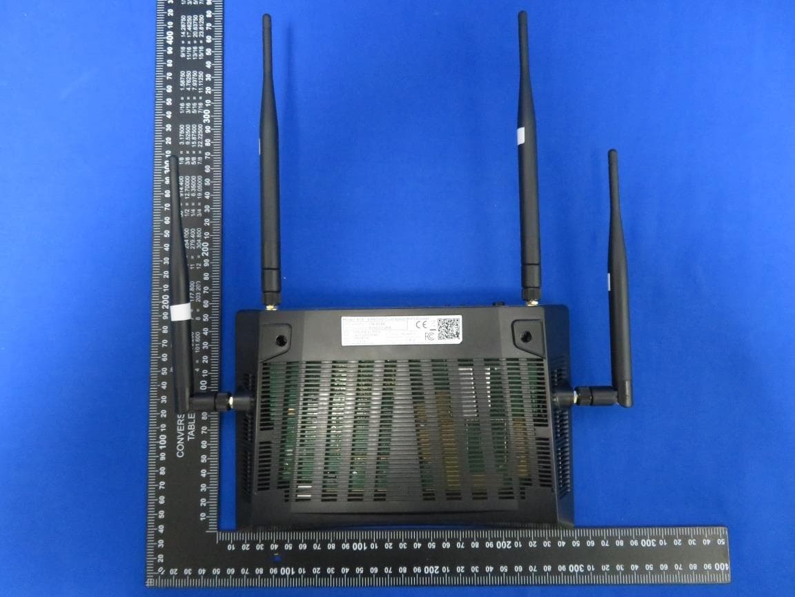
2AF5PR14
Apr 04, 2023AX6000 Dual-band WiFi Router
Equipment Class
NII - Unlicensed National Information Infrastructure TX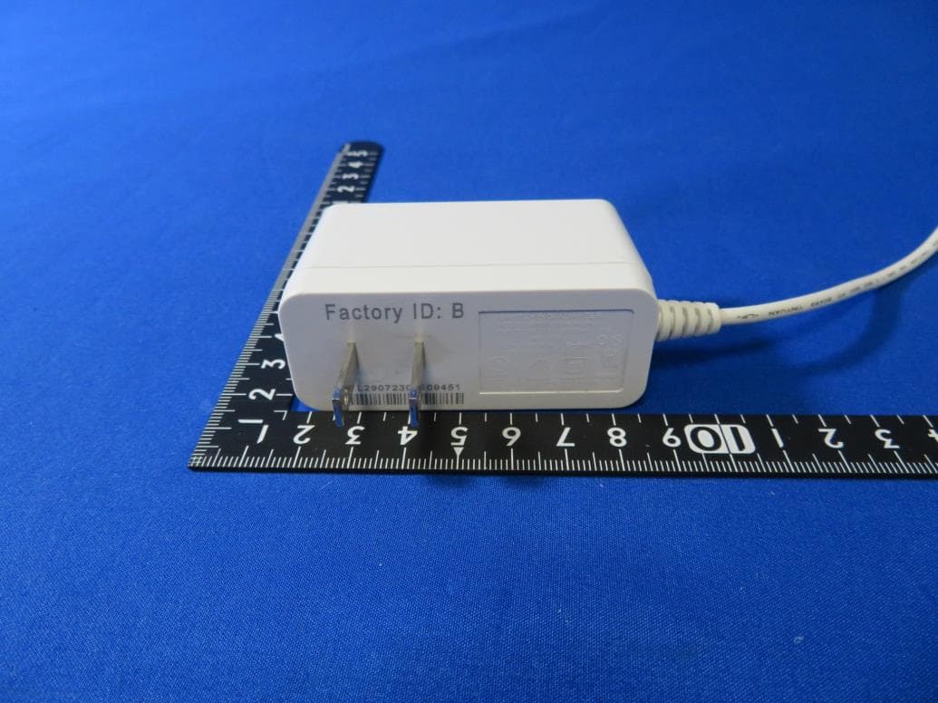
2AF5PMH7601
Aug 10, 2021AX1800 Dual-band Mesh WiFi
Equipment Class
DTS - Digital Transmission System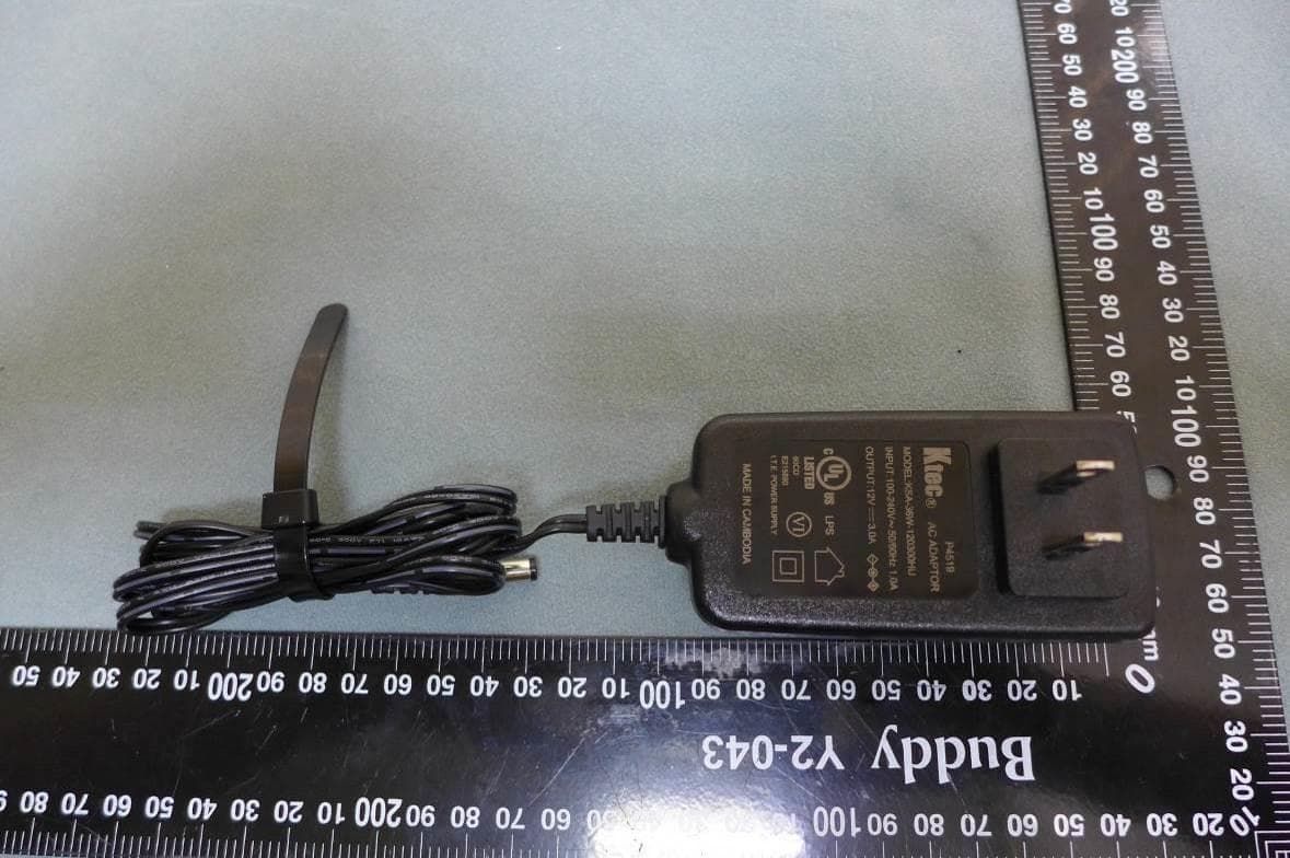
2AF5PMGMT87
Sep 20, 2020D3.1 Cable Modem plus AX6000 Router with Voice
Equipment Class
NII - Unlicensed National Information Infrastructure TX
2AF5PMH7021
Mar 26, 2020AC2200 Tri-band Mesh WiFi
Equipment Class
DTS - Digital Transmission System