2AF6B-5166WisLink Module
Shenzhen RAKwireless Technology Co.,Ltd.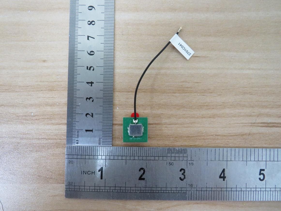
Click to zoom
Application Details
- Equipment Class
- DTS - Digital Transmission System
- Date of Grant
- Jan 12, 2026
- Application Purpose
- Original Equipment
- Equipment Note
- WisLink Module
- Frequency Range
- 923.30000000 - 927.50000000
- Country
- China
Documents & Files
Document Text
Text extracted from the exhibit documents filed with the FCC. Open a document above to read the original.
Users Manual
PAGE 1 Version 1.0 FCC Statement This equipment has been tested and found to comply with the limits for a Class B digital device, pursuant to part 15 of the FCC rules. These limits are designed to provide reasonable protection against harmful interference in a residential installation. This equipment generates, uses and can radiate radio frequency energy and, if not installed and used in accordance with the instructions, may cause harmful interference to radio communications. However, there is no guarantee that interference will not occur in a particular installation. If this equipment does cause harmful interference to radio or television reception, which can be determined by turning the equipment off and on, the user is encouraged to try to correct the interference by one or more of the following measures: -Reorient or relocate the receiving antenna. -Increase the separation between the equipment and receiver. -Connect the equipment into an outlet on a circuit different from that to which the receiver is connected. -Consult the dealer or an experienced radio/TV technician for help. This equipment complies with Part 15 of the FCC Rules. Operation is subject to the following two conditions: (1) This device may not cause harmful interference, and (2) This device must accept any interference received, including interference that may cause undesired operation. Any changes or modifications not expressly approved by the party responsible for compliance could void the user’s authority to operate the equipment. 2.2 This module has been assessed against the following FCC rule parts: CFR 47 FCC Part 15 C (15.247, DTS ). It is applicable to the modular transmitter 2.3 This radio transmitter 2AF6B-5166 has been approved by Federal Communications Commission to operate with the antenna types listed below, with the maximum permissible gain indicated. Antenna types not included in this list that have a gain greater than the maximum gain indicated for any type listed are strictly prohibited for use with this device. The concrete contents to check are the followi ng three points. 1)Maximum antenna gains are shown in item 2.7 below. 2)Should be installed so that the end user cannot modify the antenna 3)Feed line should be designed in 50ohm Fine-tuning of return loss etc. can be performed using a matching network. The antenna shall not be accessible for modification or change by the end user. 2.4 The modul e compli es with FCC Part 15.247 and appl y for Singl e modul e approval. 2.5 Trace antenna designs: Not applicable, the antenna connector for this module are integrated into the module. 2.6 This equipment complies with FCC radiation exposure limits set forth for an uncontrolled environment. This equipment should be installed and operated with a minimum distance of 20cm between the radiator & your body. This transmitter must not be co-located or operating in conjunction with any other antenna or transmitter. 2.7 The following antennas have been certified for use with this module. Only antennas of the same type with equal or lower gain may also be used with this module. Other types of antennas and/or higher gain antennas may require the additional authorization for operation. The installer should use unique antenna connector and Antenna types not included in this list that have a gain greater than the maximum gain indicated for any type listed are strictly prohibited for use with this device. The manufacturer of module will inform installer to meet with the FCC part 15.203 in the warning part. Antenna Specification list below: PAGE 2 Version 1.0 2.8 Please notice that if the FCC identification number is not visible when the module is installed inside another device, then the outside of the device into which the module is installed must also display a label referring to the enclosed module. This exterior label can use wording such as “Contains FCC ID: 2AF6B-5166”; any similar wording that expresses the same meaning may be used. 2.9 Testin g of t he host product with all t he transmitters install ed – referred to as the composite investigation test- is recommended, to verify that t he host product meets all t he applicable FCC rules. The radi o spectrum is to be investigated wit h all t he transmitters in th e final host product functioning to determine that no emissions exceed the highest limit permitted for any one individual transmitter as requir ed by Secti on 2.947(f). The host manufacturer is responsible to ensure that when their product operates as intended it d oes not have any emissions present that are out of compliance that w ere not present when the transmitters were tested individually . If t he modul ar transmitter has been full y test ed by t he modul e grant ee on the requir ed number of channels, modulation types, and modes, it should not be neces sary for the host installer to re-test all the available transmitter modes or settings. It is recommended that t he host product manufacturer, installing the modul ar transmitter, perform some investigative measurements to confirm that the resulti ng composite syst em does not ex ceed the spurious emissions limits or band edge limits (e.g., where a different antenna may be causin g additional emissions). The testi ng shoul d chec k for emissi ons that may occur due to th e intermixing of emissions wit h the other transmitters, digital circuitry, or due to physical properties of t he host product (enclosure). This investigation is especially important when integrating multipl e modul ar transmitters wh ere the certification is based on testing each of them in a stand-alone configuration. PAGE 3 Version 1.0 2.10 Any company of the host device which install this modular should perform the test of radiated & conducted emission and spurious emission etc. according to FCC Part 15C: 15.247 and 15.209 & 15.207, 15B class B requirement, only if the test result comply with FCC part 15C: 15.247 and 15.209 & 15.207,15B class B requirement. Then the host can b…
Text truncated - open the document above for the full version.
Users Manual
RAK5166 WisLink LPWAN Concentrator Datasheet Overview Product Description The RAK5166 is an LPWAN Concentrator Module with PCI Express M.2 Type 3042 form factor and Key B-M Dual Key IDs based on Semtech SX1303 and SX126X for Listen Before Talk feature, which enables easy integration into an existing router or other network equipment with LPWAN Gateway capabilities. It can be used in any embedded platform offering a free PCIe M.2 slot with a USB connection. Furthermore, the ZOE- M8Q GPS chip is integrated onboard. This module is an exceptional, complete, and cost-efficient gateway solution offering up to 10 programmable parallel demodulation paths, 8 x 8 channel LoRa packet detectors, 8 x SF5-SF12 LoRa demodulators, and 8 x SF5-SF10 LoRa demodulators. It is capable of detecting an uninterrupted combination of packets at 8 different spreading factors and 10 channels with continuous demodulation of up to 16 packets. This product is best for smart metering fixed networks and Internet-of- Things (IoT) applications. Product Features • Designed based on PCI Express M.2 Type 3042 form factor and Key B-M Dual Key IDs • SX1303 baseband processor emulates 8 x 8 channels LoRa packet detectors • 8x SF5-SF12 LoRa demodulators • 8x SF5-SF10 LoRa demodulators • Gigh-speed 125/250/500 kHz LoRa demodulator • (G)FSK demodulator • 3.3 V PCI Express M.2 • Compatible with Type 3042 Socket 2 Key B-M PCIe-based WWAN Module • Tx power up to 27 dBm • Rx sensitivity down to -139 dBm @ SF12 • BW 125 kHz • Supports global license-free frequency band (EU868, IN865, RU864, US915, AU915, KR920, AS923-1/2/3/4) • Supports USB interfaces • Listen Before Talk • Fine Timestamp • Built-in ZOE-M8Q GPS module Specifications Overview The overview shows the top and back views of the RAK5166 board. It also presents the block diagram that discusses how the board works. Board Overview RAK5166 is a compact LPWAN Gateway Module, making it suitable for integration in systems where mass and size constraints are essential. It has been designed with the PCI Express M.2 Type 3042 form factor in mind, so it can easily become a part of products that comply with the standard, where they allow cards with a thickness of at least 3.7 mm. The board has two MHF4 IPEX connectors for the LoRa and GNSS antennas and a standard 75-pin connector (M.2) with Key B-M Dual Key IDs. Block Diagram The RAK5166 concentrator is equipped with one SX1303 chip and two SX1250. The first chip is utilized for the RF signal and the core of the device, while the latter provides the related LoRa modem and processing functionalities. Additional signal conditioning circuitry is implemented for PCI Express M.2 compliance, and two MHF4 IPEX connectors are available for external antenna integration. Hardware The hardware is categorized into seven (7) parts. It discusses the interfacing, pinouts, and their corresponding functions and diagrams. It also covers the parameters and standard values of the board. Interfaces • Power Supply - The RAK5166 concentrator module must be supplied through the 3.3Vaux pins by a DC power supply. The voltage needs to be stable since the current drawn can vary significantly during operation based on the power consumption profile of the SX1303 chip (for more information, see the SX1303 Datasheet). • USB Interface - The USB interface mainly provides for the USB_D+, USB_D- pins of the system connector. The USB interface gives access to the configuration register of SX1303 via an MCU STM32L412KBU6. Only the slave side is implemented. • UART and I2C Interface - RAK5166 integrates a ZOE-M8Q GPS module which has UART and I2C interface. The PINs on the golden finger provide a UART connection and an I2C connection, which allows direct access to the GPS module. The PPS signal is not only connected to SX1303 internally but also connected to the golden finger which can be used by the host board. • GPS_PPS - RAK5166 reserved the GPS_PPS input for received packets time- stamped and Fine timestamp. • MCU RESET - RAK5166 USB card includes the RESET active-low input signal to reset the MCU. SX1303’s RESET is controlled by MCU to reset the radio operations as specified by the SX1303 Specification. • Antenna RF Interface - The module has two RF interfaces over a standard MHF4 IPEX connector with a characteristic impedance of 50 Ω. The RF port (J1) supports both Tx and Rx, providing the antenna interface for LoRa. The RF port (J2) provides the antenna interface for GPS. Pin Definition Pinout Diagram Pinout Description Type Description IO Bidirectional DI Digital input DO Digital output OC Open collector OD Open drain PI Power input PO Power output NC No connection Pin No. RAK5166 Pin Type Description Remarks 1 NC (CONFIG_3=GND) No connection by default Reserved for CONFIG_3 2 3.3 V PI 3.3 V DC supply 3 GND Ground 4 3.3 V PI 3.3 V DC supply 5 GND Ground 6 NC No connection 7 USB_D+ IO USB differential data (+) Require differential impedance of 90 Ω 8 NC No connection 9 USB_D- IO USB differential data (-) Require differential impedance of 90 Ω 10 NC No connection 11 GND Ground KEY-B Notch 20 NC No connection 21 NC (CONFIG_0=GND) No connection by default Reserved for CONFIG_0 Pin No. RAK5166 Pin Type Description Remarks 22 NC No connection 23 NC No connection 24 NC No connection 25 NC No connection 26 NC No connection 27 GND Ground 28 NC No connection 29 NC No connection 30 NC (Optional: MCU_RESET) No connection by default Reserved for MCU_RESET 31 NC No connection 32 NC No connection 33 GND Ground 34 NC No connection 35 NC No connection 36 NC No connection 37 NC No connection 38 NC No connection 39 GND Ground Pin No. RAK5166 Pin Type Description Remarks 40 NC (Optional: I2C_SCL) No connection by default Reserved for connecting to GPS module ZOE-M8Q's I2C_SCL internally 41 NC No connection 42 NC (Optional: I2C_SDA) No connection by default Reserved for connecting to GPS module ZOE-M8Q's I2C_SDA internally 43 NC No connection 44 NC No connection 45 GND Ground 46 GPS_RES…
Text truncated - open the document above for the full version.
Test Report
Page 1 of 7 900-930 MHz 8 dBi Fiber Glass Antenna (RAKARG15) Datasheet Features • Frequency range: 900 ~ 930 MHz • Max gain: 8.0 dBi • VSWR: ≤ 1.5 • Radome body: Fiberglass • High efficiency • Vertically polarized dipole • Omni-directional • Easy to mount with the included Installation kit • Outdoor use Figure 1 RAKARG16 Overview Page 2 of 7 Specifications Parameter Value Model RAKARG15 Frequency range 900 ~ 930 MHz Peak gain 8 dBi VSWR ≤ 1.5 Efficiency ≤ 65% Feed impedance 50 Ohms Radiation pattern Omni-directional Polarization Vertical Cover material (color) Fiberglass (white) Connector type N-type male Dimensions (mm) Փ 25.0 mm x 900.0 mm Operation temp (°C) -20 °C ~ +65 °C Storage temperature -30 °C ~ +75 °C Humidity range 5% ~ 95% Page 3 of 7 VSWR Frequency (MHz) VSWR 902 MHz 1.28 910 MHz 1.20 928 MHz 1.17 Figure 2: RAKARG15 VSWR graph Page 4 of 7 Peak Gain & Efficiency Frequency (MHz) Gain (dBi) Efficiency (%) 900 6.3 43.3 905 6.6 47.1 910 7.6 50.4 915 7.3 52.6 920 7.4 52.4 925 7.6 52.7 930 8.0 50.9 Average: 50.0 Page 5 of 7 Radiation Patterns IVE-900 IVH.900 Figure 3: Radiation pattern at 900MHz IVE-910 IVH-910 Figure 4: Radiation pattern at 910MHz Page 6 of 7 IVE-920 IVH-920 Figure 5: Radiation pattern at 920MHz IVE-930 to IVH.930 Figure 6: Radiation pattern at 930MHz Page 7 of 7 Mechanical Specifications Figure 7: RAKARG15 mechanical specifications Manufacturer Shenzhen RAKwireless Technology Co.,Ltd. Room 506, Building B, New Compark, Pingshan First Road, Taoyuan Street, Nanshan District, Shenzhen, Guangdong, China
Test Setup Photos
Appendix II Setup Photographs Project No.: 4791947268-1 Page 2 of 9 This report shall not be reproduced except in full, without the written approval of UL Verification Services (Guangzhou) Co., Ltd, Song Shan Lake Branch. AC Power Line Conducted Emission RAKARG15 Page 3 of 9 This report shall not be reproduced except in full, without the written approval of UL Verification Services (Guangzhou) Co., Ltd, Song Shan Lake Branch. RAKARJ14 Page 4 of 9 This report shall not be reproduced except in full, without the written approval of UL Verification Services (Guangzhou) Co., Ltd, Song Shan Lake Branch. Radiated Band edge and Spurious Emission RAKARG15 RADIATED RF MEASUREMENT SETUP (ABOVE 1 GHz) MEASUREMENT POSITION MEASUREMENT POSITION (X axis) Page 5 of 9 This report shall not be reproduced except in full, without the written approval of UL Verification Services (Guangzhou) Co., Ltd, Song Shan Lake Branch. MEASUREMENT POSITION (Y axis) MEASUREMENT POSITION (Z axis) Page 6 of 9 This report shall not be reproduced except in full, without the written approval of UL Verification Services (Guangzhou) Co., Ltd, Song Shan Lake Branch. RAKARJ14 RADIATED RF MEASUREMENT SETUP (ABOVE 1 GHz) MEASUREMENT POSITION MEASUREMENT POSITION (X axis) Page 7 of 9 This report shall not be reproduced except in full, without the written approval of UL Verification Services (Guangzhou) Co., Ltd, Song Shan Lake Branch. MEASUREMENT POSITION (Y axis) MEASUREMENT POSITION (Z axis) Page 8 of 9 This report shall not be reproduced except in full, without the written approval of UL Verification Services (Guangzhou) Co., Ltd, Song Shan Lake Branch. RADIATED RF MEASUREMENT SETUP (30MHz~1GHz) RAKARG15 RAKARJ14 Page 9 of 9 This report shall not be reproduced except in full, without the written approval of UL Verification Services (Guangzhou) Co., Ltd, Song Shan Lake Branch. RADIATED RF MEASUREMENT SETUP (Below 30MHz) RAKARG15 RAKARJ14
Test Report
The results reported herein have been performed in accordance with the laboratory’s terms of accreditation. This report shall not be reproduced except in full without the written approval of the Laboratory. The results in this report apply to the test sample(s) mentioned above at the time of the testing period only and are not to be used to indicate applicability to other similar products. CFR 47 FCC PART 15 SUBPART C CERTIFICATION TEST REPORT For WisLink Module MODEL NUMBER: RAK5166 FCC ID: 2AF6B-5166 REPORT NUMBER: 4792062441-RF-1 ISSUE DATE: November 7, 2025 Prepared for Shenzhen RAKwireless Technology Co.,Ltd. Room 506, Building B, New Compark, Pingshan First Road, Taoyuan Street, Nanshan District, Shenzhen, Guangdong, China Prepared by UL Verification Services (Guangzhou) Co., Ltd, Song Shan Lake Branch Room 101, Building 2, No.4, Information Road, Songshan Lake, Dongguan, Guangdong, China Tel: +86 769 22038881 Fax: +86 769 33244054 Website: www.ul.com REPORT NO.: 4792062441-RF-1 Page 2 of 90 UL Verification Services (Guangzhou) Co., Ltd, Song Shan Lake Branch FORM No.: 10-SL-F0087 This report shall not be reproduced except in full, without the written approval of UL Verification Services (Guangzhou) Co., Ltd, Song Shan Lake Branch. Revision History Rev. Issue Date Revisions Revised By V0 November 7, 2025 Initial Issue REPORT NO.: 4792062441-RF-1 Page 3 of 90 UL Verification Services (Guangzhou) Co., Ltd, Song Shan Lake Branch FORM No.: 10-SL-F0087 This report shall not be reproduced except in full, without the written approval of UL Verification Services (Guangzhou) Co., Ltd, Song Shan Lake Branch. Summary of Test Results Test Item Clause Limit/Requirement Result Antenna Requirement N/A FCC Part 15.203 Pass AC Power Line Conducted Emission ANSI C63.10-2020, Clause 6.2 FCC Part 15.207 Pass Conducted Output Power ANSI C63.10-2020, Clause 11.9.1.2 FCC Part 15.247 (b) (3) Pass 6dB Bandwidth and 99% Occupied Bandwidth ANSI C63.10-2020, Clause 11.8.1 FCC Part 15.247 (a) (2) Pass Power Spectral Density ANSI C63.10-2020, Clause 11.10.2 FCC Part 15.247 (e) Pass Conducted Band edge and spurious emission ANSI C63.10-2020, Clause 11.11 FCC Part 15.247 (d) Pass Radiated Band edge and Spurious Emission ANSI C63.10-2020, Clause 11.12 FCC Part 15.247 (d) FCC Part 15.209 FCC Part 15.205 Pass Duty Cycle ANSI C63.10-2020, Clause 11.6 None; for reporting purposes only. Pass Note: *This test report is only published to and used by the applicant, and it is not for evidence purpose in China. *The measurement result for the sample received is <Pass> according to < CFR 47 FCC PART 15 SUBPART C > when <Simple Acceptance> decision rule is applied. REPORT NO.: 4792062441-RF-1 Page 4 of 90 UL Verification Services (Guangzhou) Co., Ltd, Song Shan Lake Branch FORM No.: 10-SL-F0087 This report shall not be reproduced except in full, without the written approval of UL Verification Services (Guangzhou) Co., Ltd, Song Shan Lake Branch. TABLE OF CONTENTS 1. ATTESTATION OF TEST RESULTS ................................................................................. 6 2. TEST METHODOLOGY ..................................................................................................... 7 3. FACILITIES AND ACCREDITATION ................................................................................. 7 4. CALIBRATION AND UNCERTAINTY ................................................................................ 8 4.1. MEASURING INSTRUMENT CALIBRATION .............................................................. 8 4.2. MEASUREMENT UNCERTAINTY ............................................................................... 8 5. EQUIPMENT UNDER TEST ............................................................................................... 9 5.1. DESCRIPTION OF EUT .............................................................................................. 9 5.2. CHANNEL LIST ..........................................................................................................10 5.3. MAXIMUM OUTPUT POWER.....................................................................................10 5.4. TEST CHANNEL CONFIGURATION ..........................................................................10 5.5. THE WORSE CASE POWER SETTING PARAMETER ..............................................10 5.6. WORST-CASE CONFIGURATIONS...........................................................................11 5.7. DESCRIPTION OF AVAILABLE ANTENNAS AND CABLES ......................................12 5.8. DESCRIPTION OF TEST SETUP ...............................................................................13 6. MEASURING INSTRUMENT AND SOFTWARE USED ....................................................14 7. ANTENNA PORT TEST RESULTS ...................................................................................17 7.1. ON TIME AND DUTY CYCLE .....................................................................................17 7.2. 6 dB DTS BANDWIDTH AND 99 % OCCUPIED BANDWIDTH ..................................18 7.3. CONDUCTED OUTPUT POWER ...............................................................................20 7.4. POWER SPECTRAL DENSITY ..................................................................................21 7.5. CONDUCTED BANDEDGE AND SPURIOUS EMISSIONS ........................................23 8. RADIATED TEST RESULTS .............................................................................................25 8.1. SPURIOUS EMISSIONS (1 GHz ~ 10 GHz) ...............................................................30 8.1.1. Lora SF7 with RAKARG15 ...................................................................................30 8.1.2. Lora SF12 with RAKARG15 .................................................................................36 8.1.3. Lora SF7 with RAKARJ14 ....................................................................................42 8.1.4. Lora SF12 with RAKARJ14 ....…
Text truncated - open the document above for the full version.
Test Report
东莞市森岭智能科技有限公司 变更记录 MODIFICATION RECORD SHEET 版本 (REV.) 更改日期 (Modification date ) 更改内容描述(Summary of modification content) 拟制( Signature )批准( Approval ) X12024.09.25 初版发行(First Issue)胡赵海(Jerry) 朱正锐(Jongrei) DONGGUAN SLEing INTEL-TECH CO.,LTD 东莞市森岭智能科技有限公司 承认书项目表(Spec Item ) 序号 (N0. ) 项目(Project)备注(Remark) 页码 (Page) 1承认书封面(Spec Cover) 1 2 变更记录( MODIFICATION RECORD SHEET ) 2 3承认书项目表(Spec Item ) 3 4工程成品图(Drawing ) 4 5电性测试报告(Test Reports ) 5 6 6 7 S 参数测试(S Parameter Test) 7 测试设备(Test Setup) Give clear indication of: 1. The contents of the acknowledgement shall be arranged in order according to the items in the check sheet. 2. The number of copies of the acceptance letter shall be printed according to the customer's requirements, and the SGS report shall be stamped with the engineering seal. 3. All materials shall be confirmed by the customer. Any material/process/changes that may affect product quality and environmental quality must be re-sent to the customer for confirmation before import. 4. SGS report is valid for one year. 5. According to the contents attached to the actual acknowledgement, check the check form: "Yes" is provided, "no" is provided according to customer requirements. DONGGUAN SLEing INTEL-TECH CO.,LTD Φ1.13mm Coaxial Cable Black,50Ω 低损耗线 端子方向依图面 与接头剖面相反 接头 平面对平面 电性测试报告 Test Reports Electrical Properties FrequencyDC~6GHz Impedance50 0hm Nominal V.S.W.R≤1.5 Working Voltage (depending on cable type) 170V/50 Hz Insulation Resistance1000M ohm Contact Resistance Center Contact: 10m ohm Outer Contact: 5m ohm Admitted Power2 W Connector SMA+MHF Physical Properties Connector Material Brass Cable Type Ф1.13mm Black Operating Temp. -25~+75 °C Storage Temp. -25~+75 °C 东莞市森岭智能科技有限公司 DONGGUAN SLEing INTEL-TECH CO.,LTD S 参数测试 S ParameterTest 东莞市森岭智能科技有限公司 DONGGUAN SLEing INTEL-TECH CO.,LTD 东莞市森岭智能科技有限公司 测试设备 Test Setup DONGGUAN SLEing INTEL-TECH CO.,LTD
Test Report
Page 1 of 6 902-928 MHz 2.3 dBi Blade Antenna White (RAKARJ16) Datasheet Features • Frequency range: 902~928 MHz • VSWR: ≤ 1.5 • Max Gain: 2.3 dBi • High efficiency • Vertically polarized dipole Figure 1 RAKARJ16 overview Page 2 of 6 Specifications Parameter Value Model RAKARJ16 Frequency range 902 ~ 928 MHz Peak gain 2.3 dBi VSWR ≤ 1.5 Efficiency > 80% Feed impedance 50 Ohms Radiation pattern Omni-directional Polarization Vertical Cover material (color) Plastic (black) Connector type RP-SMA Dimensions (mm) Փ 13.00 mm x 198.0 mm Operation temp (°C) -30 °C ~ +75 °C Storage temperature -30 °C ~ +75 °C Humidity range 5% ~ 95% Page 3 of 6 S11&VSWR Frequency (MHz) S11 VSWR 902 MHz -18.3 1.28 928 MHz -14.6 1.46 Figure 2 Return Loss Page 4 of 6 Peak Gain & Efficiency Frequency (MHz) Peak Gain (dBi) Efficiency (%) 902 2.3 82.6 904 2.2 82.3 906 2.2 82.7 908 2.3 84.0 910 2.3 85.0 912 2.3 85.7 914 2.3 86.0 916 2.2 86.1 918 2.2 85.9 920 2.2 86.0 922 2.3 86.4 924 1.9 85.9 926 1.9 85.1 928 2.1 85.5 Average - 84.9 Page 5 of 6 Radiation Patterns 4 Page 6 of 6 Mechanical Specifications 5 Manufacturer Shenzhen RAKwireless Technology Co.,Ltd. Room 506, Building B, New Compark, Pingshan First Road, Taoyuan Street, Nanshan District, Shenzhen, Guangdong, China
Test Report
Page 1 of 6 902-928 MHz 2.3 dBi Blade Antenna White (RAKARJ14) Datasheet Features • Frequency range: 902~928 MHz • VSWR: ≤ 1.5 • Max Gain: 2.3 dBi • High efficiency • Vertically polarized dipole Figure 1 RAKARJ14 overview 1 Page 2 of 6 Specifications Parameter Value Model RAKARJ14 Frequency range 902 ~ 928 MHz Peak gain 2.3 dBi VSWR ≤ 1.5 Efficiency > 80% Feed impedance 50 Ohms Radiation pattern Omni-directional Polarization Vertical Cover material (color) Plastic (white) Connector type RP-SMA Dimensions (mm) Փ 13.00 mm x 198.0 mm Operation temp (°C) -20 °C ~ +75 °C Storage temperature -30 °C ~ +75 °C Humidity range 5% ~ 95% Page 3 of 6 S11&VSWR Frequency (MHz) S11 VSWR 902 MHz -18.3 1.28 928 MHz -14.6 1.46 Figure 2 Return Loss Page 4 of 6 Peak Gain & Efficiency Frequency (MHz) Peak Gain (dBi) Efficiency (%) 902 2.3 82.6 904 2.2 82.3 906 2.2 82.7 908 2.3 84.0 910 2.3 85.0 912 2.3 85.7 914 2.3 86.0 916 2.2 86.1 918 2.2 85.9 920 2.2 86.0 922 2.3 86.4 924 1.9 85.9 926 1.9 85.1 928 2.1 85.5 Average - 84.9 Page 5 of 6 Radiation Patterns 4 + Z + Y + X Page 6 of 6 Mechanical Specifications 5 Manufacturer Shenzhen RAKwireless Technology Co.,Ltd. Room 506, Building B, New Compark, Pingshan First Road, Taoyuan Street, Nanshan District, Shenzhen, Guangdong, China
Test Report
Page 1 of 6 902-928 MHz 5.1 dBi Fiber Glass Antenna (RAKARG19) Datasheet Features • Frequency range: 902 ~ 928 MHz • Max gain: 5.1 dBi • VSWR: ≤ 1.47 • High efficiency • Vertically polarized dipole • Omni-directional • Outdoor use Figure 1: RAKARG19 overview Page 2 of 6 Specifications Parameter Value Model RAKARG19 Frequency range 902 ~ 928 MHz Peak gain 5.1 dBi VSWR ≤ 1.47 Efficiency ≤ 84% Feed impedance 50 Ohms Radiation pattern Omni-directional Polarization Vertical Cover material (color) Fiber glass (white) Connector type N-type male Dimensions (mm) Ø 27.0 mm x 480.0 mm Operation temperature (°C) -40 °C ~ +75 °C Storage temperature (°C) -40 °C ~ +85 °C Humidity range 5% ~ 95% Page 3 of 6 VSWR Frequency (MHz) VSWR Return Loss (dB) 902 MHz 1.47 - 14.4 928 MHz 1.46 - 14.5 Figure 2: RAKARG19 VSWR graph Page 4 of 6 Peak Gain & Efficiency Frequency (MHz) Gain (dBi) Efficiency (%) 902 4.8 82 904 4.9 83 906 5.0 83 908 5.0 83 910 5.0 84 912 5.0 84 914 5.1 84 916 5.1 84 918 5.1 84 920 5.1 84 922 5.1 84 924 5.0 84 926 5.0 84 928 5.0 84 Average: 83.64 Page 5 of 6 Radiation Patterns Page 6 of 6 Mechanical Specifications Figure 4: RAKARG19 mechanical specifications Manufacturer Shenzhen RAKwireless Technology Co.,Ltd. Room 506, Building B, New Compark, Pingshan First Road, Taoyuan Street, Nanshan District, Shenzhen, Guangdong, China
Attestation Statements
Shenzhen RAKwireless Technology Co.,Ltd. Date: 10/14/2025 Federal Communications Commissions Authorization and Evaluation Division 7435 Oakland Mills Road Columbia, MD 21046 RE: CFR 47 §2.911 (d)(5) Attestation FCC ID: 2AF6B-5166 Grantee FRN: 0024961310 1.Shenzhen RAKwireless Technology Co.,Ltd.certifies that the equipment for which authorization is sought is not “covered” equipment prohibited from receiving an equipment authorization pursuant to section 2.903 of the FCC rules. 2.Shenzhen RAKwireless Technology Co.,Ltd. (“the applicant”) certifies that, the device does not have cybersecurity and / or anti-virus software produced or provided by Kaspersky Lab, Inc. or any of its successors and assignees, identified on the Covered List installed on the device, nor will it be installed by the applicant anytime after certification. 3.Shenzhen RAKwireless Technology Co.,Ltd. certifies that, as of the date of the filing of the application, the applicant is not identified on the Covered List as an entity producing “covered” equipment and is not an affiliate or subsidiary of an entity identified on the Covered List. Sincerely yours, Company Name: Shenzhen RAKwireless Technology Co.,Ltd. Contact Name: Vivian Xu Title of Person: Engineer Address: Room 506, Building B, New Compark, Pingshan First Road, Taoyuan Street, Nanshan District, Shenzhen China Date: 10/14/2025
Test Report
Page 1 of 6 902-928 MHz 5.8 dBi Fiber Glass Antenna (RAKARG14) Datasheet Features • Frequency range: 902 ~ 930 MHz • Max gain: 5.8 dBi • VSWR: ≤ 2.0 • Radome body: Fiberglass • High efficiency • Vertically polarized dipole • Omni-directional • Easy to mount with the included Installation kit • Outdoor use Page 2 of 6 Specifications Parameter Value Model RAKARG14 Frequency range 902 ~ 930 MHz Peak gain 5.8 dBi VSWR ≤ 2.0 Efficiency ≤ 79% Feed impedance 50 Ohms Radiation pattern Omni-directional Polarization Vertical Cover material (color) Fiberglass (white) Connector type N-type male Dimensions (mm) Փ 29.8 mm x 800.0 mm Operation temp (°C) -20 °C ~ +65 °C Storage temperature -30 °C ~ +75 °C Humidity range 5% ~ 95% Page 3 of 6 VSWR Frequency (MHz) VSWR 900 MHz 1.32 902 MHz 1.33 930 MHz 1.47 Figure 2: RAKARG14 VSWR graph Page 4 of 6 Peak Gain & Efficiency Frequency (MHz) Gain (dBi) Efficiency (%) 902 5.4 74.02 904 5.6 76.58 906 5.6 76.34 908 5.6 74.85 910 5.5 74.11 912 5.6 74.09 914 5.7 76.16 916 78.27 918 79.42 920 79.10 922 77.99 924 5.8 76.85 926 5.8 76.56 928 5.7 77.45 930 5.7 78.16 Average: 71.73 5.8 5.8 5.8 5.8 Page 5 of 6 Radiation Patterns Figure 3: RAKARG14 radiation patterns Page 6 of 6 Mechanical Specifications Figure 4: RAKARG14 mechanical specifications Manufacturer Shenzhen RAKwireless Technology Co.,Ltd. Room 506, Building B, New Compark, Pingshan First R…
Text truncated - open the document above for the full version.
Contact Information
Applicant
Vivian Xu(Engineer)
[email protected]Fax: +8675586152201
Test Firm
UL Verification Services (Guangzhou) Co., Ltd.Stephen Guo
Technical Specifications
| # | Rule Parts | Frequency Range | Power Output |
|---|---|---|---|
| 1 | 15C | 923.3 MHz - 927.5 MHz | 284.00 mW |
Other Applications from Shenzhen RAKwireless Technology Co.,Ltd.
2AF6B-13302
Aug 01, 2026Wisblock Wireless
Equipment Class
DTS - Digital Transmission System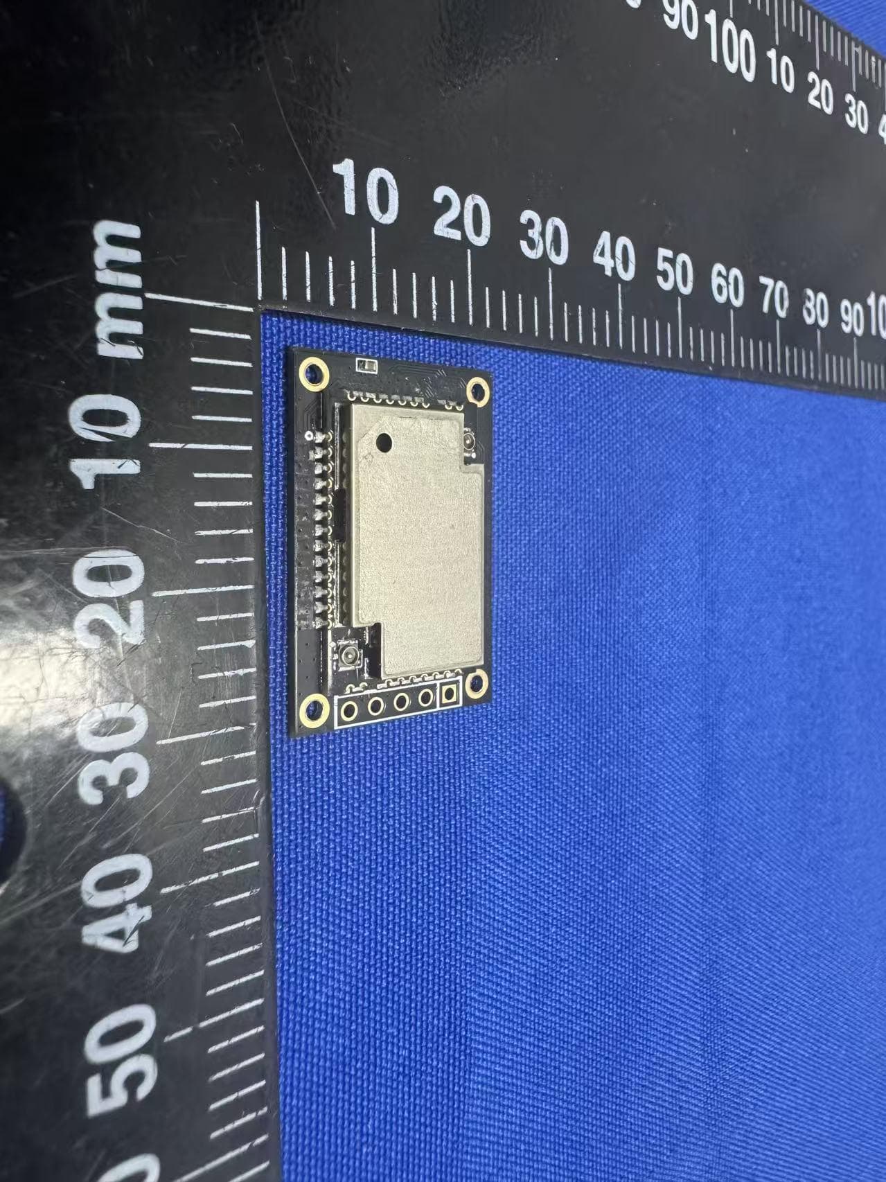
2AF6B-3112
Mar 09, 2026WisDuo Module
Equipment Class
DSS - Part 15 Spread Spectrum Transmitter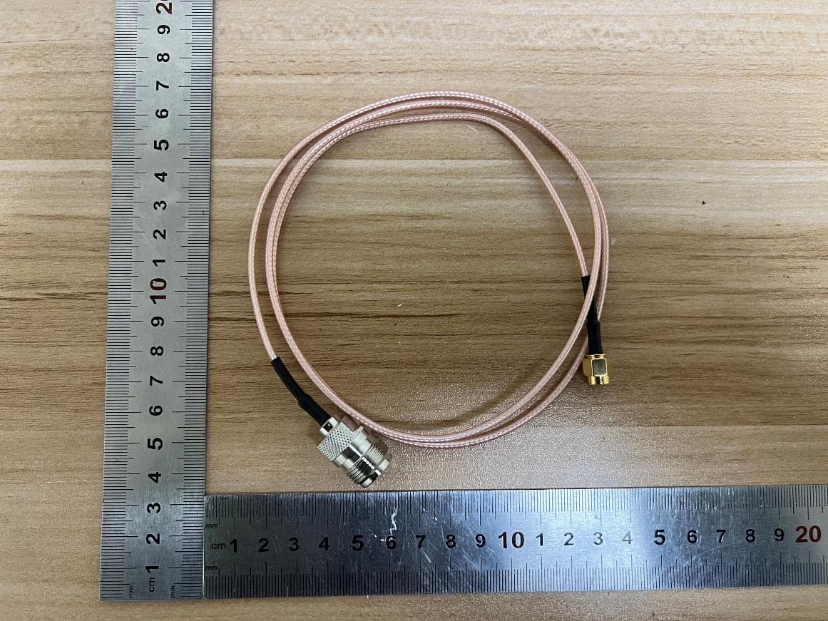
2AF6B-5167
Feb 04, 2026WisLink Module
Equipment Class
DTS - Digital Transmission System2AF6B-RAK7437
Jan 16, 2026WisGate X Industrial
Equipment Class
DTS - Digital Transmission System2AF6B-RAK7437C
Jan 16, 2026WisGate X Industrial
Equipment Class
JAB - Part 15 Class B Digital Device