2AF6B-RAK3272WisDuo LPWAN SiP
Shenzhen RAKwireless Technology Co.,Ltd.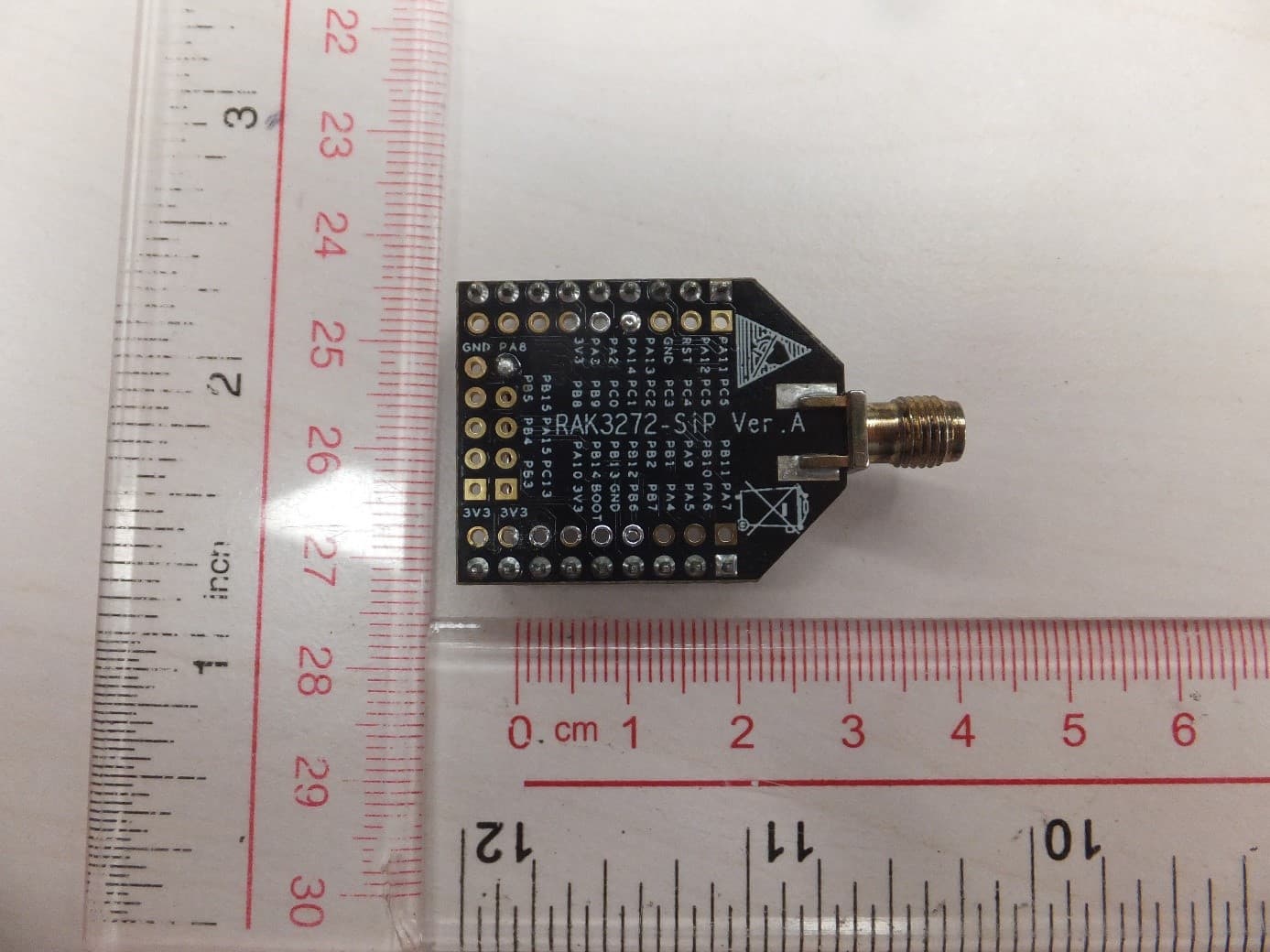
Click to zoom
Application Details
- Equipment Class
- DSS - Part 15 Spread Spectrum Transmitter
- Date of Grant
- Aug 03, 2022
- Application Purpose
- Original Equipment
- Date of Application
- Aug 03, 2022
- Equipment Note
- WisDuo LPWAN SiP
- Frequency Range
- 902.30000000 - 914.90000000
- Country
- China
Documents & Files
Document Text
Text extracted from the exhibit documents filed with the FCC. Open a document above to read the original.
Users Manual
Documentation Center Description The RAK3272-SiP Breakout Board was designed to allow easy access to the RAK3172-SiP pins to simplify development and testing. The microcontroller GPIO pins are accessible via 2.54 mm headers. The breakout board itself has a RAK3172-SiP (based on STM32WLE5) as its core. The STM32WLE5 is part of STM32WLE5x family. This core is based on an Arm® Cortex®-M4 core running at 48 MHz, and a sub-GHz radio based on Semtech SX126x. The board complies with Class A, B, & C of LoRaWAN 1.0.3 specifications and also features LoRa Point-to-Point (P2P) communication mode, which helps you in implementing your own customized long-range LoRa network quickly. It is also RUI3 compatible which allows you to create custom firmware using RUI3 APIs. Features 32-bit Arm® Cortex®-M4 48 MHz MCU and sub-GHz Semtech SX126x radio Chipset STM32WLE5 (single-core) I/O ports: UART/I2C/GPIO/SPI 32 MHz TXCO and 32 KHz xtal RUI3 API compatible Easy to use AT Command set via UART interface Serial Wire Debug (SWD) interface LoRaWAN 1.0.3 specification compliant Supported bands: IN865, EU868, AU915, US915, KR920, RU864, and AS923 Supply voltage: 1.8 V ~ 3.6 V Temperature range: -40 °C ~ 85 °C Size: 25.4 mm x 41.8 mm Specifications Overview The top view of the RAK3272-SiP Breakout Board is shown in Figure 1. WisDuo LPWAN SiP RAK3272-SiP Breakout Board Datasheet Overview Documentation Center Figure 1: RAK3272-SiP Breakout Board top view The bottom view of the RAK3272-SiP Breakout Board is shown in Figure 2. Figure 2: RAK3272-SiP Breakout Board bottom view Hardware The hardware specification is categorized into five parts. It discusses the interfacing, pinouts, and their corresponding functions and diagrams. It also covers the RF, electrical and mechanical parameters, including the tabular data of the functionalities and standard values of the RAK3272-SiP Breakout Board. Interface SWD Programing Interface When programming via an ST-Link tool, it is required to have all of the following four pins connected to your ST-Link tool: 3V3 SWDIO SWCLK GND Documentation Center For more information refer to the Upload firmware using ST-Link section. UART Interface This board has two UART interfaces: UART2 (default interface for firmware uploading and AT Commands) UART1 RF Interface J2 is the RP-SMA antenna connector. ⚠ WARNING Before powering the RAK3272-SiP Breakout Board, you should install the LoRa antenna first. Not doing so might damage the board. Make sure to use a LoRa antenna with RP-SMA male connector and compatible with the chosen LoRa frequency. Figure 3: LoRa antenna with RP-SMA male connector Pin Definition Documentation Center Figure 4: RAK3272-SiP Breakout Board J3 and J4 header The pin 1 of the headers are highlighted in a blue rectangle. Figure 5: RAK3272-SiP Breakout Board J5 to J8 header Pin on RAK3272-SiP Connection on UART-USB Adapter Documentation Center The tables below show the header definitions of the RAK3272-SiP Breakout Board: J3 Pin Definitions J4 Pin Definitions Pin on RAK3272-SiPConnection on UART-USB adapter PA2RX PA3TX 3V33.3 V GNDGround PinNameDescriptionRAK3272-SiP Pin 1I2C2_SDAI2C2 interfacePA11 2I2C2_SCLI2C2 interfacePA12 3RSTMCU ResetRST 4GNDGround- 5SWDIOPA13/SWD debug pin (SWDIO)PA13 6SWCLKPA14/SWD debug pin (SWCLK)PA14 7UART2_TXUART2/LPUART1 Interface (AT Commands and FW Update)PA2 8UART2_RXUART2/LPUART1 Interface (AT Commands and FW Update)PA3 9PA8MCU pin PA8PA8 Documentation Center J5 Pin Definitions PinNameDescriptionRAK3272-SiP Pin 1SPI1_MOSIGPIO or SPI1 (MOSI)PA7 2SPI1_MISOGPIO or SPI1 (MISO)PA6 3SPI1_CLKGPIO or SPI1 (CLK)PA5 4SPI1_NSSGPIO or SPI1 (NSS)PA4 5UART1_RXUART1 InterfacePB7 6UART1_TXUART1 InterfacePB6 7GNDGround- 8BOOT0BOOT0 mode enable pin - active high- 93V3Power Supply- Documentation Center J6 Pin Definitions PinNameDescriptionRAK3272-SiP Pin 1PC6MCU pin PC6PC6 2PC5MCU pin PC5PC5 3PC4MCU pin PC4PC4 4PC3MCU pin PC3PC3 5PC2MCU pin PC2PC2 6PC1MCU pin PC1PC1 7PC0MCU pin PC0PC0 8PB9MCU pin PB9PB9 9PB8MCU pin PB8PB8 Documentation Center J7 Pin Definitions J8 Pin Definitions PinNameDescriptionRAK3272-SiP Pin 1PB11MCU pin PB11PB11 2PB10MCU pin PB10PB10 3PA9MCU pin PA9PA9 4PB1MCU pin PB1PB1 5PB2MCU pin PB2PB2 6PB12MCU pin PB12PB12 7PB13MCU pin PB13PB13 8PB14MCU pin PB14PB14 9PA10MCU pin PA10PA10 PinNameDescriptionRAK3272-SiP Pin 13V3Power Supply- 2PC13MCU pin PC13PC13 3PA15MCU pin PA15PA15 4PB15MCU pin PB15PB15 5GNDGround- Documentation Center RF Characteristics The RAK3272-SiP Breakout Board supports the LoRaWAN bands 863 MHz to 930 MHz Operating Frequencies Electrical Characteristics RAK3272-SiP Power Supply Scheme The RAK3272-SiP Breakout Board can use two different power supply regulators: LDO or DCDC (SMPS) - Switch Mode Power Supply. PinNameDescriptionRAK3272-SiP Pin 13V3Power Supply- 2PB3MCU pin PB3PB3 3PB4MCU pin PB4PB4 4PB5MCU pin PB5PB5 5GNDGround- ModuleRegionFrequency RAK3272-SiPEuropeEU868 North AmericaUS915 AustraliaAU915 KoreaKR920 AsiaAS923 IndiaIN865 RussiaRU864 Documentation Center The use of DCDC is optional but improve the power efficiency. If you want to disable the DCDC mode, then you need to remove the L1 inductor as shown in the Figure 6. Figure 6: RAK3272-SiP Breakout Board DCDC inductor Absolute Maximum Ratings Operating Voltage ParameterMinimumTypicalMaximumUnit VDD and GPIO-0.3 V3.9Volts (V) Documentation Center Operating Current Sleep Current Power Consumption ParameterMinimumTypicalMaximumUnit VCC1.83.6Volts (V) VDDA (ADC or COMP used)1.713.6Volts (V) VDDA (VREFBUF used)2.43.6Volts (V) VDDA (ADC, COMP or VREFBUF not used)03.6Volts (V) VBAT1.553.6Volts (V) VDDSMPS1.83.6Volts (V) VDDRF1.83.6Volts (V) VDDPA1.83.6Volts (V) VREF+2.0VDDAVolts (V) VREF+ (VDDA < 2V)VDDAVDDAVolts (V) FeatureConditionMinimumTypicalMaximumUnit Operating CurrentTX Mode87 (@ 20 dBm 868 Mhz)mA RX Mode5.22mA FeatureConditionMinimumTypical (3.3V)MaximumUnit Current ConsumptionEU8681.69μA US915-μA Documentation Center Schematic Diagram Figure 7: RAK3272-SiP schematic…
Text truncated - open the document above for the full version.
Users Manual
1 Warning FCC Warning: This device complies with part 15 of the FCC Rules. Operation is subject to the following two conditions. (1) This device may not cause harmful interference; (2) This device must accept any interference received, including interference that may cause undesired operation. Any Changes or modifications not expressly approved by the party responsible for compliance could void the user's authority to operate the equipment. FCC Statement: "This equipment has been tested and found to comply with the limits for a Class B digital device, pursuant to part 15 of the FCC Rules. These limits are designed to provide reasonable protection against harmful interference in a residential installation. This equipment generates, uses and can radiate radio frequency energy and, if not installed and used in accordance with the instructions, may cause harmful interference to radio communications. However, there is no guarantee that interference will not occur in a particular installation. If this equipment does cause harmful interference to radio or television reception, which can be determined by turning the equipment off and on, the user is encouraged to try to correct the interference by one or more of the following measures: —Reorient or relocate the receiving antenna. —Increase the separation between the equipment and receiver. —Connect the equipment into an outlet on a circuit different from that to which the receiver is connected. —Consult the dealer or an experienced radio/TV technician for help." INTEGRATION INSTRUCTIONS 1. This module has been tested and found to comply with the FCC Part15.247 for Modular Approval. 2. This Modular Approval is limited to OEM installation for mobile and fixed applications only. The antenna installation and operating configurations of this transmitter, including any applicable source-based time- averaging duty factor, antenna gain and cable loss must satisfy MPE categorical Exclusion Requirements of 2.1091. This modular should be installed and operated with minimum distance 20 cm between the radiator& your body. 1 RAK2287X 1 3. The U.FL connector antenna has been approved for the modular. The maximum antenna gain is 2.3dBi. For situations where the host manufacturer is responsible for an external connector, the integration instructions shall inform the installer that a unique antenna connector must be used on the Part 15 authorized transmitters used in the host product. 4. When the module is installed in the host device, the FCC ID label must be visible through a window on the final device or it must be visible when an access panel, door or cover is easily removed. If not, a second label must be placed on the outside of the final device that contains the following text: ―Contains FCC ID: 2AF6B-RAK3272. 5. The Shenzhen Rakwireless Technology Co., Ltd. modular transmitter is only FCC authorized for the FCC Part15.247 listed on the grant, and that the host product manufacturer is responsible for compliance to any other FCC rules that apply to the host not covered by the modular transmitter grant of certification. If the grantee markets their product as being Part 15 Subpart B compliant (when it also contains unintentional- radiator digital circuity), then the grantee shall provide a notice stating that the final host product still requires Part 15 Subpart B compliance testing with the modular transmitter installed. RF Exposure: This equipment complies with FCC radiation exposure limits set forth for an uncontrolled environment. This equipment should be installed and operated with minimum distance 20 cm between the radiator and your body. This transmitter must not be co-located or operating in conjunction with any other antenna or transmitter. ISED Warning: This device contains licence-exempt transmitter(s)/receiver(s) that comply with Innovation, Science and Economic Development Canada’s licence-exempt RSS(s). Operation is subject to the following two conditions: 1. This device may not cause interference. 2. This device must accept any interference, including interference that may cause undesired operation of the device. L’émetteur/récepteur exempt de licence contenu dans le présent appareil est conforme aux CNR d’Innovation, Sciences et Développement économique Canada applicables aux appareils radio exempts de licence. L’exploitation est autorisée aux deux conditions suivantes : 1. L’appareil ne doit pas produire de brouillage; 2. L’appareil doit accepter tout brouillage radioélectrique subi, même si le brouillage est susceptible d’en compromettre le fonctionnement. 2 RAK2287X 2 This equipment complies with ISED radiation exposure limits set forth for an uncontrolled environment. This equipment should be installed and operated with minimum distance 20cm between the radiator& your body.This transmitter must not be co-located or operating in conjunction with any other antenna or transmitter located or operating in conjunction with any other antenna or transmitter. Cet équipement est conforme avec les limites d’exposition à la radiation de l’ISED émises dans un environnement contrôlé. Cet équipement devrait être installé et fonctionnel avec un minimum de distance entre le radiateur et votre corps d’au moins 20 cm. Ce transmetteur ne doit pas être co-situé près d’une autre antenne ou en conjonction avec un autre transmetteur. The host product shall be properly labelled to identify the modules within the host product. The ISED certification label of a module shall be clearly visible at all times when installed in the host product; otherwise, the host product must be labelled to display the ISED certification number for the module, preceded by the word "contains" or similar wording expressing the same meaning, as follows: Contains IC: 25908-RAK3272 Le numéro d'homologation d'ISDE, le NIVM, le NMP et le NIVL ne doivent pas nécessairement être adjacents. Le numéro d'homologation se compose d'un numéro de compagnie (NC), attribué par le Bureau d'homologation …
Text truncated - open the document above for the full version.
Cover Letter(s)
TCB Authority to Act as Agent Number: MS-0045317 Revision:0 Effective date: Oct 8, 2021 Page 1 of 1 Authority to Act as Agent Date: ___24 May 2022___________ TUV Rheinland of North America, Inc. 1279 Quarry Lane., Suite. A Pleasanton, CA 94566 To Whom It May Concern: I appoint ____TÜV Rheinland (Shenzhen) Co., Ltd._to act as our agent in the preparation of this application for equipment certification. I certify that submitted documents properly describe the device or system for which equipment certification is sought. I also certify that each unit manufactured, imported or marketed, as defined in the FCC or Industry Canada’s regulations will have affixed to it a label identical to that submitted for approval with this application. For instances where our authorized agent signs the application for certification on our behalf, I acknowledge that all responsibility for complying with the terms and conditions for Certification, as specified by TUV Rheinland Group, still resides with ____Shenzhen RAKwireless Technology Co.,Ltd. and Room 506, Building B, New Compark, Pingshan First Road, Taoyuan Street, Nanshan District, Shenzhen, Guangdong 518000, China _________. For TCB applications, We certify that we are not subject to denial of federal benefits, that includes FCC benefits, pursuant to Section 5301 of the Anti-Drug Abuse Act of 1988, 21 U.S.C. 862. Further, no party, as defined in 47 CFR 1.2002 (b), to the application is subject to denial of federal benefits, that includes FCC benefits. Thank you, Agency Agreement Date:____24 May 2022__________________________ Agreement is valid for 12 months from the above date. By: ______________________________ Vivian Xu ______________________ (Signature)(Print name) _____Project Manager__________________________+86 199 2658 4202______________ (Title)(Telephone) On behalf of: ____ Shenzhen Rakwireless Technology Co., Ltd. ______________________ (Company Name)
Cover Letter(s)
Standard Form MS-0044715Page 1 of 1Revision 0 Date: ___28 July 2022_____ Subject: Confidentiality Request for FCC ID: 2AF6B-RAK3272 and IC: 25908-RAK3272 Pursuant to FCC 47 CRF 0.457(d) and 0.459 and IC RSP-100, Section 10, the applicant requests that a part of the subject FCC/IC application be held confidential. Type of Confidentiality RequestedExhibit Short Term PermanentBlock Diagrams Short Term PermanentInternal Photos *** Short Term PermanentOperation Description/Theory of Operation Short Term PermanentTune-Up Procedure Short Term PermanentSchematics Short Term PermanentUser’s Manual*** Short Termn/aTest Setup Short Termn/aExternal Photos Shenzhen Rakwireless Technology Co., Ltd. has spent substantial effort in developing this product and it is one of the first of its kind in industry. Having the subject information easily available to "competition" would negate the advantage they have achieved by developing this product. Not protecting the details of the design will result in financial hardship. Permanent Confidentiality: The applicant requests the exhibits listed above as permanently confidential be permanently withheld from public review due to materials that contain trade secrets and proprietary information not customarily released to the public. (*** PAG only) Short-Term Confidentiality: The applicant requests the exhibits selected above as short term confidential be withheld from public view for a period of ___180___ days from the date of the Grant of Equipment Authorization and prior to marketing. This is to avoid premature release of sensitive information prior to marketing or release of the product to the public. Applicant is also aware that they are responsible to notify TUV Rheinland in the event information regarding the product or the product is made available to the public. TUV Rheinland will then release the documents listed above for public disclosure pursuant to FCC Public Notice DA 04-1705. Sincerely, By:___________________________________ Vivian Xu / Engineer ______ (Signature/Title)(Print name)
Cover Letter(s)
Difference Declaration Original Model No.:RAK3272-SiP Adding Model No.:RAK3172-SiP To whom it may concern, We, Shenzhen RAKwireless Technology Co.,Ltd. would like to declare those models RAK3172-SiP, RAK3272-SiP are identical except the construction, model RAK3272-SiP has an additional baseboard and other model model RAK3172-SiP doesn’t have, the baseboard is the extension of I/O. Sincerely yours, Applicant:Shenzhen RAKwireless Technology Co.,Ltd. Address: Room 506, Building B, New Compark, Pingshan First Road, Taoyuan Street, Nanshan District, Shenzhen, Guangdong 518000, China Signature: Name and title:Vivian Xu / Engineer Email:[email protected] Tel.:+86 199 2658 4202
External Photos
2.3 dBi antenna 0.8dBi antenna Configuration1: model RAK3172-SiP, shielding part with antenna system Configuration2: model RAK3272-SiP, the whole module
ID Label/Location Info
Printed on the shielding case
Operational Description
Tolerances (Unless otherwise specified) Unictron Technologies Corporation Website: www.unictron.com X : ± 1 X.X : ± 0.1 X.XX : ± 0.01 Angle : ± Hole Dia. : ± Scale : Unit:mm THIS SPECIFICATION IS THE PROPERTY OF UNICTRON TECHNOLOGIES CORPORATION AND SHALL NOT BE REPRODUCED OR USED IN ALL CIRCUMSTANCES WITHOUT WRITTEN PERMISSION Prepared By :Shelley Checked By :Joy Approved By : Frank TITLE: 35x 7.0 x 0.5mm ISM PCB Antenna (P3507-01) PART S2B1OD3A1L01000 REV. NO. A PAGE 1 OF 6 S23ODAL10B1 (1)(2)(3)(4)(5) 0100 35x7x0.5mm ISM PCB Antenna (P3507-01) 1. Explanation of Product Number Product Code: (1) Application: O: ISM PCB antenna (2) Dimensions: D3: 35x 7.0 x 0.5/ L=1.13*100mm+I-PEX (3) Material: A: GF (4) Working Frequencies 1L: 902~928 MHz (5) Antenna Series: 01: serial number Tolerances (Unless otherwise specified) Unictron Technologies Corporation Website: www.unictron.com X : ± 1 X.X : ± 0.1 X.XX : ± 0.01 Angle : ± Hole Dia. : ± Scale : Unit:mm THIS SPECIFICATION IS THE PROPERTY OF UNICTRON TECHNOLOGIES CORPORATION AND SHALL NOT BE REPRODUCED OR USED IN ALL CIRCUMSTANCES WITHOUT WRITTEN PERMISSION Prepared By :Shelley Checked By :Joy Approved By : Frank TITLE: 35x 7.0 x 0.5mm ISM PCB Antenna (P3507-01) PART S2B1OD3A1L01000 REV. NO. A PAGE 2 OF 6 2. Features *Stable and reliable in performances *Compact size *RoHS compliance 3. Applications *ISM915 band *Smart meters *Wireless alarm and security system *Industrial monitoring and control *IOT applications 4. Description Unictron’s P3507-01 PCB antenna is designed for ISM 915 MHz band applications, covering frequencies 902~928 MHz. Fabricated with proprietary design and processes. 5. Electrical Specifications (Antenna is attached on a 2.0mm-thick ABS + PC material plate) 5-1. Electrical Table: Characteristics Specifications Unit Outline Dimensions 35 x 7.0 x 0.5 mm Working Frequency 902~928 MHz VSWR 2 Max. (typical). Characteristic Impedance 50 Polarization Linear Polarization Peak Gain 0.8 dBi Efficiency 41.9 % Tolerances (Unless otherwise specified) Unictron Technologies Corporation Website: www.unictron.com X : ± 1 X.X : ± 0.1 X.XX : ± 0.01 Angle : ± Hole Dia. : ± Scale : Unit:mm THIS SPECIFICATION IS THE PROPERTY OF UNICTRON TECHNOLOGIES CORPORATION AND SHALL NOT BE REPRODUCED OR USED IN ALL CIRCUMSTANCES WITHOUT WRITTEN PERMISSION Prepared By :Shelley Checked By :Joy Approved By : Frank TITLE: 35x 7.0 x 0.5mm ISM PCB Antenna (P3507-01) PART S2B1OD3A1L01000 REV. NO. A PAGE 3 OF 6 5-2. Return Loss & Smith Chart Return Loss Smith Chart 6. Antenna Dimensions (unit: mm) . Tolerances (Unless otherwise specified) Unictron Technologies Corporation Website: www.unictron.com X : ± 1 X.X : ± 0.1 X.XX : ± 0.01 Angle : ± Hole Dia. : ± Scale : Unit:mm THIS SPECIFICATION IS THE PROPERTY OF UNICTRON TECHNOLOGIES CORPORATION AND SHALL NOT BE REPRODUCED OR USED IN ALL CIRCUMSTANCES WITHOUT WRITTEN PERMISSION Prepared By :Shelley Checked By :Joy Approved By : Frank TITLE: 35x 7.0 x 0.5mm ISM PCB Antenna (P3507-01) PART S2B1OD3A1L01000 REV. NO. A PAGE 4 OF 6 7. Radiation Pattern 7-1. 3D Gain Pattern (Radiation Pattern @ 915 MHz) X Z Y Tolerances (Unless otherwise specified) Unictron Technologies Corporation Website: www.unictron.com X : ± 1 X.X : ± 0.1 X.XX : ± 0.01 Angle : ± Hole Dia. : ± Scale : Unit:mm THIS SPECIFICATION IS THE PROPERTY OF UNICTRON TECHNOLOGIES CORPORATION AND SHALL NOT BE REPRODUCED OR USED IN ALL CIRCUMSTANCES WITHOUT WRITTEN PERMISSION Prepared By :Shelley Checked By :Joy Approved By : Frank TITLE: 35x 7.0 x 0.5mm ISM PCB Antenna (P3507-01) PART S2B1OD3A1L01000 REV. NO. A PAGE 5 OF 6 7-2. 3D Efficiency Table 7-3. 3D Efficiency vs. Frequency Tolerances (Unless otherwise specified) Unictron Technologies Corporation Website: www.unictron.com X : ± 1 X.X : ± 0.1 X.XX : ± 0.01 Angle : ± Hole Dia. : ± Scale : Unit:mm THIS SPECIFICATION IS THE PROPERTY OF UNICTRON TECHNOLOGIES CORPORATION AND SHALL NOT BE REPRODUCED OR USED IN ALL CIRCUMSTANCES WITHOUT WRITTEN PERMISSION Prepared By :Shelley Checked By :Joy Approved By : Frank TITLE: 35x 7.0 x 0.5mm ISM PCB Antenna (P3507-01) PART S2B1OD3A1L01000 REV. NO. A PAGE 6 OF 6 8. Revision Control: Revision Date Content Remark A Jul.09.2021 New Issued. N/A
Operational Description
1 KRAKBJ2701C01A 1 Features Frequency Range: 902~928MHz Quite good VSWR Max Gain: 2.3dBi High efficiency Vertically polari Specifications ModelKRAKBJ2701C01A Electrical Specifications Frequency Range902MHz~928MHz Peak Gain2.3 dBi VSWR Efficiency>80% Feed Impedance50 Ohms PolarizationVertical 2 KRAKBJ2701C01A 2 Mechanical Specifications Cover material(color)Plastic(White) InterfaceRPSMA Dimensions (mm)13.0mm x 198.0mm Operation Temp (°C)-30°C ~ +75°C Humidity range5%~95% S11&VSWR Frequency(MHz)S11VSWR 902MHz-18.31.28 928MHz-14.61.46 3 KRAKBJ2701C01A 3 Peak Gain & Efficiency Frequency(MHz)Peak Gain (dBi)Efficiency (%) 9022.382.6 9042.282.3 9062.282.7 9082.384.0 9102.385.0 9122.385.7 9142.386.0 9162.286.1 9182.285.9 9202.286.0 9222.286.4 9241.985.9 9261.985.1 9282.185.5 Average-84.9 4 KRAKBJ2701C01A 4 Patterns +Z +Y +X 5 KRAKBJ2701C01A 5 Mechanical Specifications
Operational Description
1 KRAKBJ2701C01C 1 Features Frequency Range: 902~928MHz Quite good VSWR Max Gain: 2.3dBi High efficiency Vertically polari Specifications ModelKRAKBJ2701C01C Electrical Specifications Frequency Range902MHz~928MHz Peak Gain2.3 dBi VSWR Efficiency>80% Feed Impedance50 Ohms PolarizationVertical 2 KRAKBJ2701C01C 2 Mechanical Specifications Cover material(color)Plastic(Black) InterfaceRPSMA Dimensions (mm)13.0mm x 198.0mm Operation Temp (°C)-30°C ~ +75°C Humidity range5%~95% S11&VSWR Frequency(MHz)S11VSWR 902MHz-18.31.28 928MHz-14.61.46 3 KRAKBJ2701C01C 3 Peak Gain & Efficiency Frequency(MHz)Peak Gain (dBi)Efficiency (%) 9022.382.6 9042.282.3 9062.282.7 9082.384.0 9102.385.0 9122.385.7 9142.386.0 9162.286.1 9182.285.9 9202.286.0 9222.286.4 9241.985.9 9261.985.1 9282.185.5 Average-84.9 4 KRAKBJ2701C01C 4 Patterns +Z +Y +X 5 KRAKBJ2701C01C 5 Mechanical Specifications
RF Exposure Info
Prüfbericht - Produkte Test Report - Products Prüfbericht - Nr.: Test Report No. CN22LKDS 001 Seite 28 von 30 Page 28 of 30 6Safety Human Exposure 6.1Radio Frequency Exposure Compliance 6.1.1Electromagnetic Fields RESULT:Pass Test Specification Test standard: CFR47 FCC Part 2: Section 2.1091 CFR47 FCC Part 1: Section 1.1310 FCC KDB Publication 447498 v06 FCC KDB Publication 865664 D02 v01r02 OET Bulletin 65 (Edition 97-01) RSS-102 Issue 5 March 2019 This module has three different antennas, and the maximum e.r.i.p. configuration be evaluated as below: FCC requirement: Systems operating under the provisions of this section shall be operated in a manner that ensures that the public is not exposed to radio frequency energy level in excess limit for maximum permissible exposure. In accordance with 47 CFR FCC Part 2 Subpart J, section 2.1091 this device has been defined as a mobile device whereby a distance of 20cm normally can be maintained between the user and the device. MPE Calculation Method according to OET Bulletin 65 Power Density: S (mW/cm 2 ) = PG/4πR 2 or EIRP/4πR 2 Where: S = power density (mW/cm 2 ) P = power input to the antenna (mW) G = power gain of the antenna in the direction of interest relative to an isotropic radiator R = distance to the center of radiation of the antenna (cm) The worst-case mode (the configuration having highest EIRP) specified: Lora DTS: 13.21 dBm with 2.3 dBi antenna gain From the RF output power, the minimum mobile separation distance, d=20 cm, as well as the antenna gain, the RF power density can be calculated as below: For Lora DTS: S (mW/cm 2 ) = PG/4πR 2 = 0.007 mW/cm 2 Limits for Maximum Permissible Exposure (MPE) according to FCC Part 1.1310: 1.0 mW/cm2 Prüfbericht - Produkte Test Report - Products Prüfbericht - Nr.: Test Report No. CN22LKDS 001 Seite 29 von 30 Page 29 of 30 IC requirements: The EUT shall comply with the requirement of RSS-102 section 2.5.2. Exemption from Routine Evaluation Limits – RF Exposure Evaluation RF exposure evaluation is required if the separation distance between the user and/or bystander and the device’s radiating element is greater than 20 cm, except when the device operates as follows: at or above 300 MHz and below 6 GHz and the source-based, time-averaged maximum e.i.r.p. of the device is equal to or less than 1.31 x 10 -2 ƒ 0.6834 W (adjusted for tune-up tolerance), where ƒ is in MHz; RF exposure evaluation exempted power for Lora FHSS & DTS: 1.37 W The worst-case mode (the configuration having highest EIRP) specified: Lora DTS: 13.21 dBm Antenna Gain: 2.3 dBi The Max. e.i.r.p. for Lora DTS: 15.51dBm = 0.036 W Both e.i.r.p. for the Lora FHSS and Lora DTS are less than the RF exposure evaluation exempted power. So RF exposure evaluation is not required. “RF Radiation Exposure Statement Caution: This Transmitter must be installed to provide a separation distance of at least 20 cm from all persons.”
Test Report
Prüfbericht - Produkte Test Report - Products Prüfbericht-Nr.: Test report no.: CN22LKDS 001 Auftrags-Nr.: Order no.: 168373838 Seite 1 von 30 Page 1 of 30 Kunden-Referenz-Nr.: Client reference no.: N/A Auftragsdatum: Order date: 2022-05-24 Auftraggeber: Client: Shenzhen RAKwireless Technology Co.,Ltd. Room 506, Building B, New Compark, Pingshan First Road, Taoyuan Street, Nanshan District, Shenzhen, Guangdong, China Prüfgegenstand: Test item: WisDuo LPWAN SiP Bezeichnung / Typ-Nr.: Identification / Type no.: RAK3172-SiP, RAK3272-SiP (Trademark: RAK) Auftrags-Inhalt: Order content: FCC and IC approval Prüfgrundlage: Test specification: CFR47 FCC Part 15: Subpart C Section 15.247 CFR47 FCC Part 15: Subpart C Section 15.207 CFR47 FCC Part 15: Subpart C Section 15.209 CFR47 FCC Part 2: Section 2.1093 RSS-247 Issue 2 February 2017 RSS-Gen Issue 5 February 2021 RSS-102 Issue 5 February 2021 Wareneingangsdatum: Date of sample receipt: 2022-05-24 Please refer to photo documents Prüfmuster-Nr.: Test sample no.: A003266647 Prüfzeitraum: Testing period: 2022-05-25 - 2022-07-22 Ort der Prüfung: Place of testing: TÜV Rheinland (Shenzhen) Co., Ltd. Prüflaboratorium: Testing laboratory: TÜV Rheinland (Shenzhen) Co., Ltd. Prüfergebnis*: Test result*: Pass geprüft von: tested by: X Signed by: Alex Lan genehmigt von: authorized by: X Signed by: Winnie Hou Datum: Date: 2022-08-03 Ausstellungsdatum: Issue date: 2022-08-04 Stellung / Position Assistant Project Manager Stellung / Position Department Manager Sonstiges / Other: FCC ID: 2AF6B-RAK3272 IC: 25908-RAK3272, HVIN: RAK3172-SiP, RAK3272-SiP Zustand des Prüfgegenstandes bei Anlieferung: Condition of the test item at delivery: Prüfmuster vollständig und unbeschädigt Test item complete and undamaged: * Legende: 1 = sehr gut 2 = gut 3 = befriedigend 4 = ausreichend 5 = mangelhalt P(ass) = entspricht o.g. Prüfgrundlage(n) F(ail) = entspricht nicht o.g. Prüfgrundlage(n) N/A = nicht anwendbar N/T = nicht getestet Legend: 1 = very good 2 = good 3 = satisfactory 4 = sufficient 5 = poor P(ass) = passed a.m. test specifications(s) F(ail) = failed a.m. test specifications(s) N/A = not applicable N/T = not tested Dieser Prüfbericht bezieht sich nur auf das o.g. Prüfmuster und darf ohne Genehmigung der Prüfstelle nicht auszugsweise vervielfältigt werden. Dieser Bericht berechtigt nicht zur Verwendung eines Prüfzeichens. This test report only relates to the a. m. test sample. Without permission of the test center this test report is not permitted to be V05 duplicated in extracts. This test report does not entitle to carry any test mark. TUV Rheinland (Shenzhen) Co., Ltd. 1601 R&D Room, 1602-1604, 17-18F, Building 7 Site C, Vanke Cloud City Phase I, Xingke First Street, Xili Street, Xili Community, Nanshan District, Shenzhen 518052, P.R. China Mail: [email protected] http://www.tuv.com Prüfbericht - Produkte Test Report - Products Prüfbericht - Nr.: Test Report No. CN22LKDS 001 Seite 2 von 30 Page 2 of 30 Test Summary 5.1.1 ANTENNA REQUIREMENT RESULT: Pass 5.1.2 MAXIMUM CONDUCTED OUTPUT POWER RESULT: Pass 5.1.3 CONDUCTED POWER SPECTRAL DENSITY RESULT: Pass 5.1.4 6DB BANDWIDTH RESULT: Pass 5.1.5 20DB BANDWIDTH RESULT: Pass 5.1.6 99% BANDWIDTH RESULT: Pass 5.1.7 CONDUCTED SPURIOUS EMISSIONS MEASURED IN 100 KHZ BANDWIDTH RESULT: Pass 5.1.8 RADIATED SPURIOUS EMISSION RESULT: Pass 5.1.9 CARRIER FREQUENCY SEPARATION RESULT: Pass 5.1.10 NUMBER OF HOPPING FREQUENCY RESULT: Pass 5.1.11 TIME OF OCCUPANCY RESULT: Pass 5.1.12 CONDUCTED EMISSION ON AC MAINS RESULT: Pass 6.1.1 ELECTROMAGNETIC FIELDS RESULT: Pass Prüfbericht - Produkte Test Report - Products Prüfbericht - Nr.: Test Report No. CN22LKDS 001 Seite 3 von 30 Page 3 of 30 Contents 1 GENERAL REMARKS ......................................................................................................................5 1.1 COMPLEMENTARY MATERIALS ........................................................................................................5 2 TEST SITES ...................................................................................................................................6 2.1 TEST FACILITIES .....................................................................................................…
Text truncated - open the document above for the full version.
Contact Information
Applicant
Vivian Xu(Engineer)
Technical Contact
Shenzhen RAKwireless Technology Co.,Ltd.Vivian Xu
[email protected]+8619926584202
Room 506, Building B, New Compark, Pingshan · Shenzhen · China
Test Firm
TUV Rheinland (Shenzhen) Co., Ltd.Gina Yang
[email protected]86 755 8268 1497
Technical Specifications
| # | Rule Parts | Frequency Range | Power Output |
|---|---|---|---|
| 1 | 15C | 902.3 MHz - 914.9 MHz | 20.90 mW |
Other Applications from Shenzhen RAKwireless Technology Co.,Ltd.
2AF6B-13302
Aug 01, 2026Wisblock Wireless
Equipment Class
DTS - Digital Transmission System
2AF6B-3112
Mar 09, 2026WisDuo Module
Equipment Class
DSS - Part 15 Spread Spectrum Transmitter
2AF6B-5167
Feb 04, 2026WisLink Module
Equipment Class
DTS - Digital Transmission System2AF6B-RAK7437
Jan 16, 2026WisGate X Industrial
Equipment Class
DTS - Digital Transmission System2AF6B-RAK7437C
Jan 16, 2026WisGate X Industrial
Equipment Class
JAB - Part 15 Class B Digital Device