2AF6B-RAK4270HLoRa Module
Shenzhen RAKwireless Technology Co.,Ltd.
Click to zoom
Application Details
- Equipment Class
- DTS - Digital Transmission System
- Date of Grant
- Sep 07, 2020
- Application Purpose
- Original Equipment
- Date of Application
- Sep 07, 2020
- Equipment Note
- LoRa Module
- Frequency Range
- 903.00000000 - 914.20000000
- Country
- China
Documents & Files
Document Text
Text extracted from the exhibit documents filed with the FCC. Open a document above to read the original.
Users Manual
Specification for RAK4270 LoRa Module WisDuo-LoRa Series Version V1.2 | Apr2020 www.RAKwireless.com Visit our web site for more document. 2 Table of Contents 1. General Overview ................................................................................................... 3 Introduction ................................................................................................................................. 3 Main Features ............................................................................................................................. 3 2. RAK4270 LoRa Module ............................................................................................... 4 Device Overview ........................................................................................................................ 4 Supported LoRaWAN bands ................................................................................................. 4 Block Diagram ............................................................................................................................ 5 Pin Definition & Pin Out .......................................................................................................... 5 Power Consumption ................................................................................................................. 7 Recommended Circuit ............................................................................................................. 7 SWD programming Port ..................................................................... 8 UART ports ............................................................................................... 8 I2C port ................................................................................................ 9 RF port ................................................................................................. 9 VDD power in ............................................................................................... 9 Mechanical Dimensions ......................................................................................................... 10 Recommended Footprint ...................................................................................................... 11 Recommended Reflow Profile ............................................................................................. 12 Customer Support ................................................................................................................ 12 3. Revision History ................................................................................................... 13 4. Document Summary ............................................................................................ 13 3 1. General Overview Introduction The RAK4270 LoRa Module includes a STM32L071 MCU and a SX1262 LoRa chip, which supports 8 spreading factors (SF5 ~ SF12) and signal bandwidth that can be adjusted between 7.8 kHz to 500 kHz. The module complies with the LoRaWAN 1.0.2 protocol, so it can be used for implementing LoRa networks or Lora point to point communications. The module is suitable for various applications that require long range data acquisition and low power consumption, such as: smart meters, supply chain and logistics tracking, agricultural sensors, smart cities, etc This module is expected to be controlled by an external controller through its UART interface by sending a set of AT commands. These AT commands control not only the state of this module but also set the LoRaWan communication parameters and payloads (see RAK AT Command Manual). Main Features LoRa module is suitable for applications in Smart City, Smart Agriculture, Smart Industry. Compact form factor: 15 x 15.5 x 2.5 mm (LxWxH). 20 pin stamp pad for PCB SMT board-to -board soldering. I/O ports: UART/I2C/GPIO. AT commands control interface Temperature range: -40°C to +85°C Supply voltage: 2.0 to 3.6V Frequency Bands 433MHz(EU)/ 470-510MHz(CN)/ 865-867MHz(IN)/ 863–870MHz (EU)/ 500kHz: 903–914.2MHz,125kHz:902.3-914.9MHz(US)/915-928MHz(AU)/ 920- 923MHz(KR) / 920- 923MHz(AS) LoRa bandwidth range of 7.8 kHz to 500 kHz, SF5 to SF12, BR=0.018~62.5 kb/s Ultra-low power Consumption: 1.5uA in sleep mode Arm Cortex-M0+ 32-bit RISC core. 128 kbytes flash memory with ECC 4 20 kbytes RAM 6 kbytes of data EEPROM with ECC Compliance with [TBC][add regulations here] 2. RAK4270 LoRa Module Device Overview Figure 1 shows the top view of the RAK4270 LoRa module. The dimensions of the module are 15 x 15.5 x 2.5 mm. Figure 1 | RAK4270 LoRa module Supported LoRaWAN bands The RAK4270 LoRa module supports the high LoRaWAN bands (refer to the Table 1) Module Region Frequency (MHz) RAK4270(L) Europe EU433 China CN470 RAK4270(H) Indian IN865 Europe EU868 North America US915 Australia AU915 Korea KR920 Asia AS923 Table 1 | Operating Frequencies 5 Pin Definition & Pin Out The Figure 3 shows the pinout of the RAK4270 LoRa module. Figure 2 | Pinout 6 The table below shows the pin definition of the RAK4270 LoRa Module. Pin Name I/O Description Alternate functions 1 UART2_RX I This UART port is used as an AT command port (STM32L071KBU6 PA3) USART1_RX, I2C1_SDA 2 UART2_TX O This UART port is used as an AT command port (STM32L071KBU6 PA2) MCO, USART1_TX, I2C1_SCL, I2C3_SMBA 3 UART2_DE I/O GPIO (STM32L071KBU6 PA1) SPI1_MOSI,EVENTOUT, USART1_RTS_DE, COMP2_OUT 4 UART1_TX I/O This UART port can be used as an AT command port and an upgrade port (STM32L071KBU6 PA9) TIM21_CH1,TIM2_CH3, USART2_TX,LPUART1_TX, COMP2_OUT,COMP2_INM, ADC_IN2 5 UART1_RX I/O This UART port can be used as an AT command port and an upgrade port (STM32L071KBU6 PA10) TIM21_CH2,TIM2_CH4, USART2_RX,LPUART1_RX, COMP2_INP,ADC_IN3 6 UART1_DE I/O General GPIO or UART(Reserved) (STM32L071KBU6 PA12) EVENTOUT,TIM2_CH2,USART2_RT S_DE, TIM21_ETR, USART4_RX,COMP1_INP, ADC_IN1 7 SWDIO I/O Programming (STM32L071KBU6 PA13) SWDIO, LPUART1_RX 8 SWCLK I/…
Text truncated - open the document above for the full version.
Cover Letter(s)
QA-FR-170-B Shenzhen Rakwireless Technology Co., Ltd. Address: Room 506, Bldg B, New Compark, Pingshan First Road, Taoyuan Street, XiLi town Nanshan District, Shenzhen, China Email: [email protected] Tel: +8675586152201 FCC Authorization 2020-08-06 FEDERAL COMMUNICATIONS COMMISSIONS Authorization and Evaluation Division 7435 Oakland Mills Road Columbia, MD 21046 Subject: Agent Authorization To whom it may concern: We (Shenzhen Rakwireless Technology Co., Ltd.), the undersigned, hereby authorize Bay Area Compliance Laboratories Corporation to act on its behalf in all matters relating to application for Equipment authorization, including the signing of all documents relating to these matters. All acts carried out by Bay Area Compliance Laboratory Corporation on our behalf shall have the same effect as our own action. We, the undersigned, hereby certify that we are not subject to a denial of federal benefits, that includes FCC benefits, pursuant to Section 5301 of the Anti-Drug Abuse Act of 1988, 21 U.S.C. 862. This authorization is valid until further written notice from the applicant. Sincerely, Signature: duiye ye Title: Engineer
Cover Letter(s)
Shenzhen Rakwireless Technology Co., Ltd. Address: Room 506, Bldg B, New Compark, Pingshan First Road, Taoyuan Street, XiLi town Nanshan District, Shenzhen, China Email: [email protected] Tel: +8675586152201 FCC Confidential Authorization 2020-08-06 FEDERAL COMMUNICATIONS COMMISSIONS Authorization and Evaluation Division 7435 Oakland Mills Road Columbia, MD 21046 Subject: Confidentiality Request regarding application for certification of FCC ID: 2AF6B-RAK4270H In accordance with Sections 0.457 and 0.459 of the Commission’s Rules, (Shenzhen Rakwireless Technology Co., Ltd. ) hereby requests long-term confidential treatment of information accompanying this application as outlined below: Block Diagram Schematics Operation Description The above materials contain proprietary and confidential information not customarily released to the public. The public disclosure of these materials provides unjustified benefits to its competitors in the market. Sincerely, Signature: duiye ye Title: Engineer
Cover Letter(s)
Shenzhen Rakwireless Technology Co., Ltd. Address: Room 506, Bldg B, New Compark, Pingshan First Road, Taoyuan Street, XiLi town Nanshan District, Shenzhen, China Email: [email protected] Tel: +8675586152201 Modular Approval Letter Date: 2020-08-31 FEDERAL COMMUNICATIONS COMMISSIONS Authorization and Evaluation Division 7435 Oakland Mills Road Columbia, MD 21046 Dear Application Examiner, We, Shenzhen Rakwireless Technology Co., Ltd. is submitting this application for certification of product named as LoRa Module, Model Numbers: RAK4270(H) (FCC ID: 2AF6B-RAK4270H). It is seeking modular approval. The radio meets the requirements for modular approval as detailed in FCC 15.212. Compliance to each of the requirements is described below: 1. “The modular transmitter must have its own RF shielding.” Yes, it is fulfilled. The radio portion of the module has its own RF shielding. The shielding is installed at the factory. Please see the EUT photos. 2. “The modular transmitter must have buffered modulation/data inputs.” Yes, it is fulfilled. The EUT has buffered data inputs to insure compliance with Part 15 requirements under conditions of excessive data rates or over modulation. Please see the Schematics exhibit. 3. “The modular transmitter must have its own power supply regulation.” Yes, it is fulfilled. The EUT has its own power supply regulation to insure compliance. 4. “The modular transmitter must comply with the antenna requirements of Section 15.203 and 15.204(c).” Yes. The EUT has a e xternal rod antenna design. 5. “The modular transmitter must be tested in a stand-alone configuration.” Yes, it is fulfilled. The EUT was tested in a stand-alone configuration. 6. “The modular transmitter must be labeled with its own FCC ID number.” Yes, it is fulfilled. The module will be labeled with its own FCC ID number. Please see FCC ID label & location exhibit. 7. “The modular transmitter must comply with any specific rule or operating requirements applicable to the transmitter and the manufacturer must provide adequate instructions along with the module to explain any such requirements.” Yes, it is fulfilled. The necessary explanation to be complied with this requirement is contained in the user manual, and please refer to the User manual. 8. “The modular transmitter must comply with any applicable RF exposure requirements.” Yes, it is fulfilled. The module will comply with all applicable RF exposure requirements in its intended configuration/integration in a host. Please contact me if you have additional questions. Your attention to this matter is greatly appreciated. Sincerely Yours, Signature: duiye ye Title: Engineer
External Photos
Bay Area Compliance Laboratories Corp. (Shenzhen) Project No.: RSZ200709005-RF Page 1 of 3 EXHIBIT B - EUT EXTERNAL PHOTOGRAPHS Bay Area Compliance Laboratories Corp. (Shenzhen) Project No.: RSZ200709005-RF Page 2 of 3 Antenna Antenna 1 Antenna 2 Bay Area Compliance Laboratories Corp. (Shenzhen) Project No.: RSZ200709005-RF Page 3 of 3
ID Label/Location Info
Bay Area Compliance Laboratories Corp. (Shenzhen) Project No.: RSZ200709005-RF EXHIBIT A - FCC ID LABEL AND LOCATION FCC ID Label FCC ID Label Location Information The label shown shall be permanently affixed at a conspicuous location on the device and be readily visible to the user at the time purchase (Labeling requirements per 2.925)
Internal Photos
Bay Area Compliance Laboratories Corp. (Shenzhen) Project No.: RSZ200709005-RF Page 1 of 1 EXHIBIT C - EUT INTERNAL PHOTOGRAPHS
RF Exposure Info
Bay Area Compliance Laboratories Corp. (Shenzhen) Report No.: RSZ200709005-00B FCC Part 15.247 Page 11 of 33 FCC §15.247 (i) & §2.1091- MAXIMUM PERMISSIBLE EXPOSURE (MPE) Applicable Standard According to subpart 15.247 (i) and subpart 2.1091 systems operating under the provisions of this section shall be operated in a manner that ensures the public is not exposed to RF energy level in excess of the communication guidelines. Limits for General Population/Uncontrolled Exposure Limits for General Population/Uncontrolled Exposure Frequency Range (MHz) Electric Field Strength (V/m) Magnetic Field Strength (A/m) Power Density (mW/cm 2 ) Averaging Time (Minutes) 0.3-1.34 614 1.63 *(100) 30 1.34-30 824/f 2.19/f *(180/f 2 ) 30 30-300 27.5 0.073 0.2 30 300-1500 / / f/1500 30 1500-100,000 / / 1.0 30 f = frequency in MHz * = Plane-wave equivalent power density Result Calculated Formulary: Predication of MPE limit at a given distance S = 2 4R PG S = power density (in appropriate units, e.g. mW/cm2) P = power input to the antenna (in appropriate units, e.g., mW). G = power gain of the antenna in the direction of interest relative to an isotropic radiator, the power gain factor, is normally numeric gain. R = distance to the center of radiation of the antenna (appropriate units, e.g., cm) Frequency (MHz) Maximum Antenna Gain Tune up conducted power Evaluation Distance (cm) Power Density (mW/cm 2 ) MPE Limit (mW/cm 2 ) (dBi) (numeric) (dBm) (mW) 903.0-914.2 2.3 1.7 12.0 15.85 20 0.005 0.602 Note: To maintain compliance with the FCC’s RF exposure guidelines, place the equipment at least 20cm from nearby persons. Result: Compliance
Test Report
Note: This report must not be used by the customer to claim product certification, approval, or endorsement by A2LA* or any agency of the Federal Government. This report may contain data that are not covered by the A2LA accreditation and are marked with an asterisk “★”. BACL is not responsible for the authenticity of any test data provided by the applicant. Data included from the applicant that may affect test results are marked with an asterisk ’*’. Customer model name, addresses, names, trademarks etc. are not considered data. This report cannot be reproduced except in full, without prior written approval of the Company. Unless otherwise stated the results shown in this test report refer only to the sample(s) tested. This report is valid only with a valid digital signature. The digital signature may be available only under the Adobe software above version 7.0. FCC PART 15.247 TEST REPORT For Shenzhen Rakwireless Technology Co., Ltd. Room 506, Bldg B, New Compark, Pingshan First Road, Taoyuan Street, XiLi town, Nanshan District, Shenzhen, China FCC ID: 2AF6B-RAK4270H Report Type: Original Report Product Type: LoRa Module Re port Number: RSZ200709005-00B Re port Date: 2020-08-17 Reviewed B y: Jimmy Xiao RF Engineer Prepared By: Bay Area Compliance Laboratories Corp. (Shenzhen) 6/F., West Wing, Third Phase of Wanli Industrial Building, Shihua Road, Futian Free Trade Zone, Shenzhen, Guangdong, China Tel: +86-755-33320018 Fax: +86-755-33320008 www.baclcorp.com.cn Bay Area Compliance Laboratories Corp. (Shenzhen) Report No.: RSZ200709005-00B FCC Part 15.247 Page 2 of 33 TABLE OF CONTENTS GENERAL INFORMATION ....................................................................................................................................... 4 PRODUCT DESCRIPTION FOR EQUIPMENT UNDER TEST (EUT) ..................................................................................... 4 OBJECTIVE ................................................................................................................................................................... 4 RELATED SUBMITTAL(S)/GRANT(S) ............................................................................................................................. 4 TEST METHODOLOGY .................................................................................................................................................. 4 MEASUREMENT UNCERTAINTY .................................................................................................................................... 5 SYSTEM TEST CONFIGURATION .......................................................................................................................... 6 DESCRIPTION OF TEST CONFIGURATION ...................................................................................................................... 6 EQUIPMENT MODIFICATIONS ....................................................................................................................................... 6 EUT EXERCISE SOFTWARE .......................................................................................................................................... 6 EQUIPMENT MODIFICATIONS ....................................................................................................................................... 6 DUTY CYCLE ................................................................................................................................................................ 7 SUPPORT EQUIPMENT LIST AND DETAILS .................................................................................................................... 7 EXTERNAL I/O CABLE .................................................................................................................................................. 7 BLOCK DIAGRAM OF TEST SETUP ................................................................................................................................ 8 SUMMARY OF TEST RESULTS ............................................................................................................................... 9 TEST EQUIPMENT LIST ......................................................................................................................................... 10 FCC §15.247 (i) & §2.1091- MAXIMUM PERMISSIBLE EXPOSURE (MPE) ........................................................ 11 APPLICABLE STANDARD ............................................................................................................................................ 11 RESULT ...................................................................................................................................................................... 11 FCC §15.203 - ANTENNA REQUIREMENT ........................................................................................................... 12 APPLICABLE STANDARD ............................................................................................................................................ 12 ANTENNA CONNECTOR CONSTRUCTION .................................................................................................................... 12 FCC §15.207 (a) – AC LINE CONDUCTED EMISSIONS ..................................................................................... 13 APPLICABLE STANDARD ............................................................................................................................................ 13 EUT SETUP ................................................................................................................................................................ 13 EMI TEST RECEIVER SETUP ....................................................................................................................................... 13 TEST PROCEDURE ................................................................................................…
Text truncated - open the document above for the full version.
Test Setup Photos
EXHIBIT D - TEST SETUP PHOTOGRAPHS Conducted Emissions - Front View Conducted Emissions - Side View Radiated Emissions View (Below 1 GHz) Radiated Emissions View (Above 1 GHz)
Contact Information
Applicant
Vivian Xu(Engineer)
Test Firm
Bay Area Compliance Laboratories Corp. (Shenzhen)Well Wang
[email protected]+86 (0) 755 33320018
Technical Specifications
| # | Rule Parts | Frequency Range | Power Output |
|---|---|---|---|
| 1 | 15C | 903 MHz - 914.2 MHz | 14.00 mW |
Other Applications from Shenzhen RAKwireless Technology Co.,Ltd.
2AF6B-13302
Aug 01, 2026Wisblock Wireless
Equipment Class
DTS - Digital Transmission System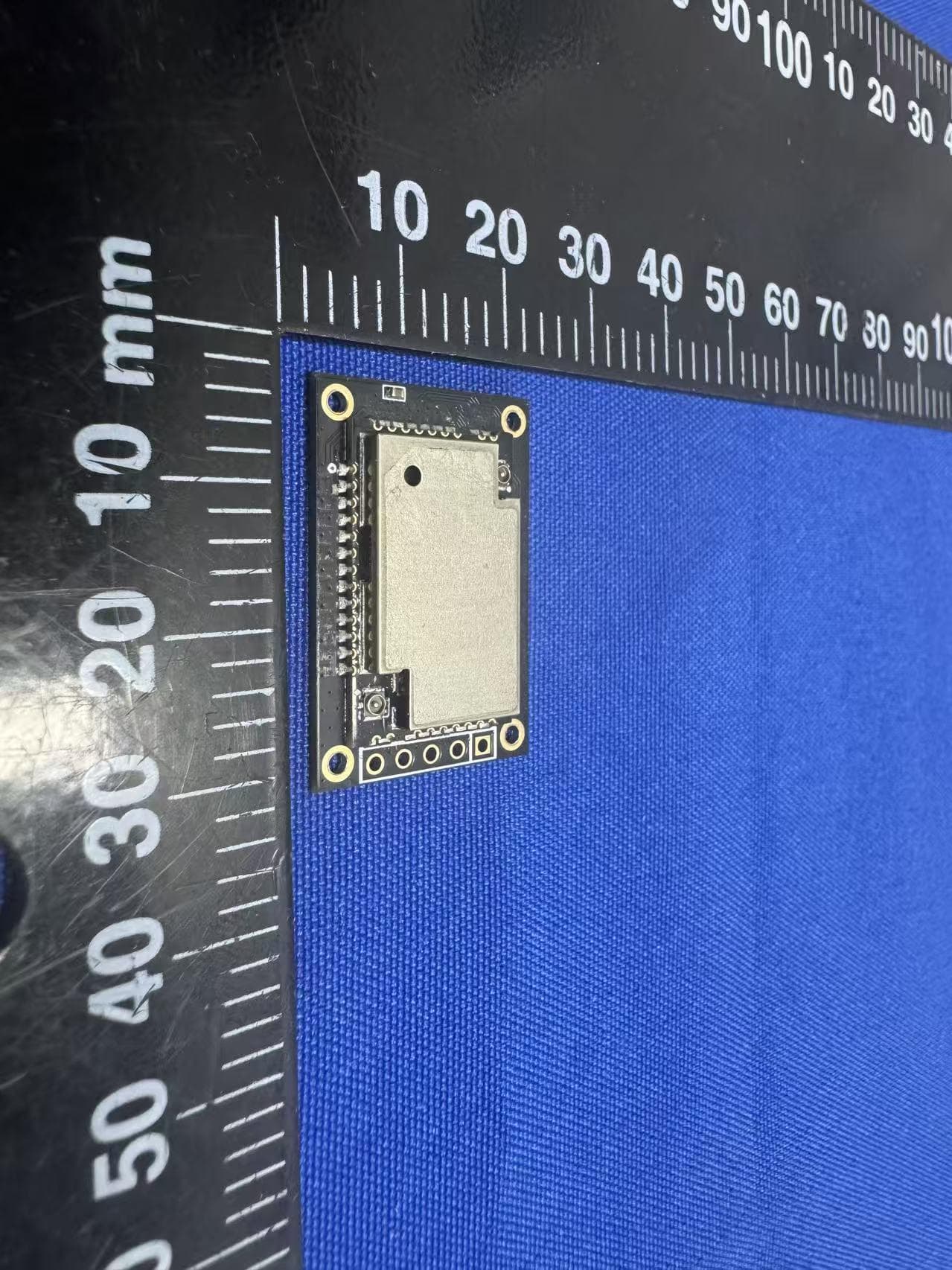
2AF6B-3112
Mar 09, 2026WisDuo Module
Equipment Class
DSS - Part 15 Spread Spectrum Transmitter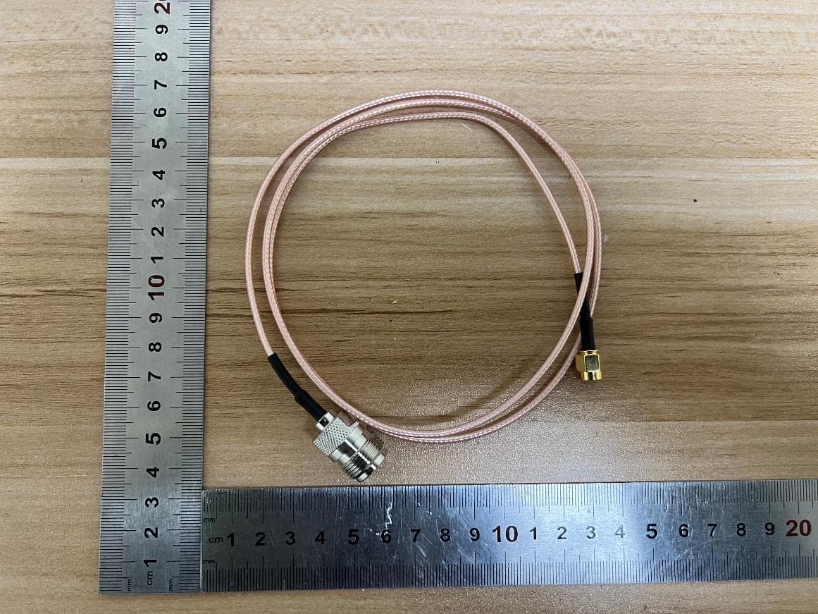
2AF6B-5167
Feb 04, 2026WisLink Module
Equipment Class
DTS - Digital Transmission System2AF6B-RAK7437
Jan 16, 2026WisGate X Industrial
Equipment Class
DTS - Digital Transmission System2AF6B-RAK7437C
Jan 16, 2026WisGate X Industrial
Equipment Class
JAB - Part 15 Class B Digital Device