2AFD9Q6MOBILE PHONE
MOVEON TECHNOLOGY LIMITED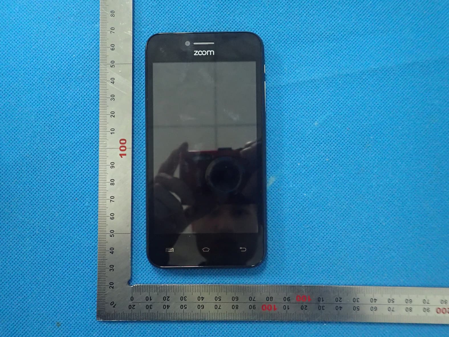
Click to zoom
Application Details
- Equipment Class
- JBP - Part 15 Class B Computing Device Peripheral
- Date of Grant
- Jan 26, 2016
- Application Purpose
- Original Equipment
- Date of Application
- Jan 26, 2016
- Equipment Note
- MOBILE PHONE
- Company
- MOVEON TECHNOLOGY LIMITED
- Country
- China
Documents & Files
Document Text
Text extracted from the exhibit documents filed with the FCC. Open a document above to read the original.
Users Manual
Q6 1 Contents 1. APPEARANCE AND KEYPAD OPERATIONS .................................................... 1 2. USING MEMORY CARD AS U DISK ........................................................... 2 4. BLUETOOTH .......................................................................................... 3 5. MAIL ................................................................................................... 4 6. DIALLING ........................................................................................... 5 7. MESSAGING .......................................................................................... 6 8. CONTACTS ........................................................................................... 7 9. INTERNET EXPLORER ............................................................................ 8 10. RECORDER ......................................................................................... 9 11.CLOCK ................................................................................................ 9 12.CACULATOR ......................................................................................... 9 13. CAMERA ............................................................................................. 9 14. IMAGES ........................................................................................... 11 15. MUSIC ............................................................................................ 11 16. CALENDER ....................................................................................... 13 17. FM RADIO ..................................................................................... 13 18. SETTINGS ....................................................................................... 13 1. Appearance and Keypad Operations Keys Functions Home Press this button to return home from any application or interface. Press it to open recently opened application window. Menu Press it to start the menu,which allows you to perform actions in the current interface or options’ menu. Back Press it to return to the previous interface,or to close dialog box 、options’ menu、notification panel or the keypad. Power Press it to open the phone’s menu,then you could choose to lock the screen、turn off the phone, or set it to the silent mode . UP Press it to increase the volume Press it to turn the phone to vibration mode from the silent mode. Down Press it to decrease the volume. Proximity Sensor Cover it, and then the phone’s backlight will turn off. Front Entering the camera interface, switched to Q6 2 Camera the front camera can photo yourself. LED Light Display mobile phone status and prompt unread messages 2. Using Memory Card as U Disk If you want to send music, pictures or other files to the phone’s memory card from the computer,you should set memory card as u disk first. Set memory card as u disk 1) Connect the phone to the computer with USB cable. The notification icon will appear in the status box. 2) Open the notification panel. 3) In the notification panel, touch USB is connected ,then touch“Open the USB Storage Device”. Notices:If you connect your phone to the computer then choose open the USB device, the phone can’t read the memory card. You temporarily can not use some applications, such as camera. Uninstall the U Disk from computer The same as the method of connecting it,see the following picture: 3. Wifi Wi-Fi provides as far as 300feet (100M) range of wireless network access. If you use cell phone to connect wifi, you should connect to the wireless access point or 「hot spots」. Notices:The availability and coverage of Wi-Fi signal depend on the number, infrastructure and other objects penetrated by the signal. Open Wi-fi and to connect to the wireless network 1) Press home>menu,then touch settings>wifi and internet 2) Select the wi-fi box,to open Wi-Fi. Phone will automatically scan for available wireless networks. 3) Touch Wi-Fi settings. Then a list of Wi-Fi network will show the founded network name and security settings. (open network or WEP、WPA/WPA2 with password).If you enable the notification in Wi-Fi settings, The status box will show this icon () when open available wireless network founded. 4) Touch one of the Wi-Fi choices to connect the network. When you choose open network, phone will connect to it automatically. If you choose WEP、WPA/WPA2 with password, you should type the password first, then touch to connect it. Notices:when the phone is connected to the wireless network, The status box will show this Wi-Fi icon(), and the approximate signal strengthen (the number of lit bars).If touch the connected network,will display the name of Wi—Fi network, status, speed, signal, strength, security, information and IP address. If you want to delete the wireless settings, please touch “not reserve” as in the right picture. If you want to connect to this network, you should re-enter these settings. Notices: Unless you choose not to reserve the network, otherwise, there is no need to re-enter Q6 3 the corresponding password when next time connecting to the previously encrypted wireless network. Wi-Fi will search automatically, that is, phone needn’t to perform additional steps to connect Wi-Fi networks. Notices: Unless you choose not to reserve the network with password, otherwise, there is no need to re-enter the corresponding password when next time connecting to the previously encrypted wireless network. Wi-Fi will search automatically, that is, phone needn’t to perform additional steps to connect Wi-Fi networks. Connect to other Wi-Fi networks 1) In the interface of wireless and network, touch Wi-Fi settings. The founded Wi-Fi networks will show on the Wi-Fi network list. 2) Touch other Wi-Fi networks, and then you can connect to this network. Notices:in addition, you can surf the internet via GPRS. We default that the GPRS in SIM1 is opened after started, users can select manually ,the spe…
Text truncated - open the document above for the full version.
Attestation Statements
MOVEON TECHNOLOGY (HK) CO., LTD. Room 3201, Building A, World Trading Plaza Block, Futian Rd., Futian Distric, Shenzhen, China Federal Communications Commission Authorization and Evaluation Division Equipment Authorization Branch 7435 Oakland Mills Road Columbia, MD 21046 DATE 2016-01-08 To whom it may concern: We, the undersigned, hereby authorize Eurofins Product Service GmbH to act on our behalf in all matters relating to applications for equipment authorization FCC ID: 2AFD9Q6 including the signing of all documents related to these matters. Any and all acts carried out by Eurofins Product Service GmbH on our behalf shall have the same effect as acts of our own. We also hereby certify that no party to this application is subject to a denial of benefits, including FCC benefits, pursuant to Section 5301 of the Anti-Drug Abuse Act of 1988, 21 U.S.C. 862. Sincerely, MOVEON TECHNOLOGY LIMITED Contact person: Joyce Yang Title: Manager
Cover Letter(s)
MOVEON TECHNOLOGY (HK) CO., LTD. Room 3201, Building A, World Trading Plaza Block, Futian Rd., Futian Distric, Shenzhen, China Federal Communications Commission Equipment Authorization Branch 7435 Oakland Mills Road Columbia, MD 21046 1/8/2016 Request for Confidentiality Company name: MOVEON TECHNOLOGY LIMITED FCC ID: 2AFD9Q6 FCC Part 15 Certification Gentlemen, In accordance with CFR 47 § 0.459, MOVEON TECHNOLOGY LIMITED hereby requests confidentiality of following attachments: Schematics Bill of Materials/Parts List Block Diagrams Theory of Operation Tune-up Procedure These documents contain detailed system and equipment description and related information about the product which MOVEON TECHNOLOGY LIMITED considers to be proprietary, confidential and a custom design and otherwise would not release to the general public. Since the design is a basis from which future technological products will evolve, MOVEON TECHNOLOGY LIMITED considers that this information would be of benefit to its competitors and that the disclosure of the information in these documents would give competitors an unfair advantage in the market. Sincerely, Company Officer: Joyce Yang Telephone Number: 0755-82912504 Email: [email protected]
External Photos
External Photos TOTAL VIEW OF EUT TOP VIEW OF EUT BOTTOM VIEW OF EUT FRONT VIEW OF EUT BACK VIEW OF EUT LEFT VIEW OF EUT RIGHT VIEW OF EUT
ID Label/Location Info
FCC ID Model: Brand FCC ID Label Lo : Q6 d Name: ZOO D: 2AFD9Q6 ocation M
Internal Photos
Internal Photos OPEN VIEW OF EUT‐1 GSM & WCDMA An tenna BT&WIFI Antenna OPEN VIEW OF EUT‐2 OPEN VIEW OF EUT‐3 INTERNAL VIEW OF EUT‐1 INTERNAL VIEW OF EUT‐2
Operational Description
MOVEON TECHNOLOGY (HK) CO., LTD. Room 3201, Building A, World Trading Plaza Block, Futian Rd., Futian Distric, Shenzhen, China Declaration concerning Antenna Specification It is hereby declared that the product Model No.: Q6 FCC ID: 2AFD9Q6 fulfills the requirement in FCC test relating to the antenna type. The device specified above confirms to the FCC recommendations for PCB antenna type described below: Model No. of antenna: N/A Type of antenna: Integrated Antenna permanently attached Gain of the antenna: 0.8 dBi Frequency range: BT: 2402-2480MHz WLAN: 2412-2462MHz Model No. of antenna: N/A Type of antenna: Integrated Antenna permanently attached Gain of the antenna: -1.0dBi Frequency range: GSM 850 : 824.2~848.8MHz; PCS 1900: 1850.2~1909.8MHz; WCDMA FDD Band II: 1852.4 -1907.6MHz WCDMA FDD Band V: 826.4-846.6MHz The mounting of the antenna is fixed to the radio module and no other antenna should be used. Company name: MOVEON TECHNOLOGY LIMITED Address: Room 3201, Building A, World Trading Plaza Block, Futian Rd., Futian Distric, City: Shenzhen ZIP / Postal code: 518000 Country: China Place: Shenzhen Date: 2016-01-08 Signature:
Parts List/Tune Up Info
TUNE UP PROCEDURE The General Information of the Device FCC ID 2AFD9Q6 Model Name Q6 Brand Name ZOOM Hard ware Version A3-02 Soft ware Version a3e_ax_tm_q6_b2b5_zoom_v06_07122015 Power Supply DC3.7V by Battery Battery parameter: DC3.7V/1300 mAh Frequency Band GSM 850PCS1900 (U.S. Bands) GSM 900 DCS 1800 (Non-U.S. Bands) UMTS FDD Band II UMTS FDD Band V (U.S. Bands) GSM Talking Avg. Output Power GSM 850 :30.5dBm+1 dB, PCS1900 : 27.5dBm+1 dB GPRS with 1 TX slot Avg. Output Power GSM 850 :30dBm+1 dB, PCS1900 : 27dBm+1 dB GPRS with 2 TX slot Avg. Output Power GSM 850 :28dBm+1 dB, PCS1900 : 25dBm+1 dB GPRS with 3 TX slot Avg. Output Power GSM 850 :26dBm+1 dB, PCS1900 : 23dBm+1 dB GPRS with 4 TX slot Avg. Output Power GSM 850 :25dBm+1 dB, PCS1900 : 22dBm+1 dB WCDMA RMC UMTS BAND II:20.5dBm+1dB; UMTS BAND V:20.5dBm+1dB WCDMA AMR UMTS BAND II:20.5dBm+1dB; UMTS BAND V:20.5dBm+1dB HSDPA Subtest 1 UMTS BAND II:20dBm+1dB; UMTS BAND V:20dBm+1dB HSDPA Subtest 2 UMTS BAND II:20dBm+1dB; UMTS BAND V:20dBm+1dB HSDPA Subtest 3 UMTS BAND II:20dBm+1dB; UMTS BAND V:20dBm+1dB HSDPA Subtest 4 UMTS BAND II:20dBm+1dB; UMTS BAND V:20dBm+1dB HSUPA Subtest 1 UMTS BAND II:20dBm+1dB; UMTS BAND V:20dBm+1dB HSUPA Subtest 2 UMTS BAND II:20dBm+1dB; UMTS BAND V:20dBm+1dB HSUPA Subtest 3 UMTS BAND II:20dBm+1dB; UMTS BAND V:20dBm+1dB HSUPA Subtest 4 UMTS BAND II:20dBm+1dB; UMTS BAND V:20dBm+1dB HSUPA Subtest 5 UMTS BAND II:20dBm+1dB; UMTS BAND V:20dBm+1dB Max.AVG. Output Power(GFSK) 4dBm±1dB Max. AVG. Output Power(π /4-DQPSK) 3dBm±1dB Max. AVG. Output Power(8-DPSK) 3dBm±1dB Max. Peak Output Power(BT4.1) -1dBm±1dB Max. AVG. Output Power(802.11b) 10dBm±1dB Max. AVG. Output Power(802.11g) 9.0dBm±1dB Max. AVG. Output Power(802.11n) 9.0dBm±1dB Max. AVG. Output Power(802.11n 40) 7.0dBm±1dB The Configuration Block Diagram for Tune UP The Detailed Procedure Of Tune Up 1 Adjustment of RF Output Power: 1.1 The equipment setup as shown in Figure 1 1.2 Operation of PC adjusts equipment 1.3 Use RF Engineering Tools at PC side 1.3.1 Select GSM850 Band: 1.3.1.1 Set GSM850 Band 1.3.1.2 Set ARFCN: 190 1.3.1.3 TX ON 1.3.1.4 Adjust the power to 33dBm (Power control level: PCL=5) by PA DAC value 1.3.1.5 Repeat 4) for 15 times,and adjust the power level to 32,31, 29, 27, 25, 23, 21, 19, 17, 15, 13, 11, 9,7, 5 1.3.1.6 Make 16 Ramp-Up/Ramp-Down data from the adjustment value of (5) and (6). 1.3.1.7 Data of 5) and 6) is written to flash memory. 1.3.2 SelectPCS1900 Band: 1.3.2.1 Set PCS Band 1.3.2.2 Set ARFCN: 661 1.3.2.3 TX ON 1.3.2.4 Adjust the power to 30dBm (Power control level: PCL=0) by PA DAC value 1.3.2.5 Repeat 4) for 15 times,and adjust the power level to 29,28, 26, 24, 22, 20, 18, 16, 14, 12, 10, 8, 6,4, 2, 0 1.3.2.6 Make 16 Ramp-Up/Ramp-Down data from the adjustment value of (5) and (6) 1.3.2.7 Data of 5) and 6) is written to flash memory. 2 Adjustment of oscillation frequency of VCXO: PC RF Tester GPIB Cable UART Cable RF Cable Test sample 2.1 The equipment setup as shown in Figure 1 2.2 Use Crystal AFC Control Tools to Set CapID and AFC DAC value 2.3 Set Band=GSM850,Set ARFCN=190,Set PCL=12 2.3.1 Set AFC DAC=4096,fixed.(Check that Vafc=1.4V) 2.3.2 Set CapID=0, and verify that frequency error >>10KHz 2.3.3 Set CapID=63, and verify that frequency error <<-10KHz 2.3.4 If the above 3 items are verified, then change CapID value to make frequency error be closed to 0 Hz as possible, record this CapID value 2.3.5 Set CapID value got from step 4), then change AFC DAC value to make frequency error be closed to 0 Hz as possible, record this AFC DAC value. 2.3.6 Download the CapID value and AFC DAC value to flash memory. 3 Adjustment of RX Sensitivity: 3.1 Select GSM850 Band: 3.1.1 Set BCCH level:-85dBm; ARFCN:128 3.1.2 Test sample make a call to connect RF Tester 3.1.3 Set TCH level:-106dBm 3.1.4 Measure BERII error at TCH ARFCN:128, 190,251 3.1.5 Tune up the RX matching circuit to make sure BERII<2% at each ARFCN. 3.2 Select PCS Band: 3.2.1 Set BCCH level:-85dBm;ARFCN:512 3.2.2 Test sample make a call to connect RF Tester 3.2.3 Set TCH level:-106dBm 3.2.4 Measure BERII error at TCH ARFCN:512, 661, 810 3.2.5 Tune up the RX matching Circuit to make sure BERII<2% at each ARFCN.
RF Exposure Info
CALIBRATION DATA PROBE CALIBRATION DATA DAE CALIBRATION DATA DIPOLE CALIBRATION DATA
RF Exposure Info
Report No.: AGC00653151201FH01 Page 1 of 12 TEST SETUP PHOTOGRAPHS & EUT PHOTOGRAPHS Test Setup Photographs LEFT-CHEEK TOUCH LEFT-TILT 15 0 Report No.: AGC00653151201FH01 Page 2 of 12 RIGHT-CHEEK TOUCH RIGHT-TILT 15 0 Report No.: AGC00653151201FH01 Page 3 of 12 Body Back 10mm Body Front 10mm 10mm Report No.: AGC00653151201FH01 Page 4 of 12 Edge 1(Top) Edge 2(Right) Report No.: AGC00653151201FH01 Page 5 of 12 Edge 4(Left) Report No.: AGC00653151201FH01 Page 6 of 12 DEPTH OF THE LIQUID IN THE PHANTOM—ZOOM IN Note:The position used in the measurement were according to IEEE 1528-2013 850MHz head 850MHz body 1900MHz head 1900MHz body 2450MHz head 2450MHz body
RF Exposure Info
Page 1 of 93 SAR Test Report Report No.: AGC00653151201FH01 FCC ID : 2AFD9Q6 APPLICATION PURPOSE : Original Equipment PRODUCT DESIGNATION : MOBILE PHONE BRAND NAME : ZOOM MODEL NAME : Q6 CLIENT : MOVEON TECHNOLOGY LIMITED DATE OF ISSUE : Jan. 21,2016 STANDARD(S) : IEEE Std. 1528:2013 FCC 47CFR § 2.1093 IEEE/ANSI C95.1:1992 REPORT VERSION : V1.0 Attestation of Global Compliance(Shenzhen) Co., Ltd. CAUTION: This report shall not be reproduced except in full without the written permission of the test laboratory and shall not be quoted out of context. Report No.: AGC00653151201FH01 Page 2 of 93 Report Revise Record Report Version Revise Time Issued Date Valid Version Notes V1.0 / Jan. 21,2016 Valid Original Report Report No.: AGC00653151201FH01 Page 3 of 93 Test Report Certification Applicant Name MOVEON TECHNOLOGY LIMITED Applicant Address world trade plaza-A block #3201-3202 Fuhong Road, Futian Manufacturer Name MOVEON TECHNOLOGY LIMITED Manufacturer Address world trade plaza-A block #3201-3202 Fuhong Road, Futian Product Designation MOBILE PHONE Brand Name ZOOM Model Name Q6 Different Description N/A EUT Voltage DC3.7V by battery Applicable Standard IEEE Std. 1528:2013 FCC 47CFR § 2.1093 IEEE/ANSI C95.1:1992 Test Date Jan. 08,2016 to Jan. 18,2016 Performed Location Attestation of Global Compliance(Shenzhen) Co., Ltd. 2 F, Building 2, No.1-No.4, Chaxi Sanwei Technical Industrial Park, Gushu, Xixiang Street, Bao'an District, Shenzhen, China Report Template AGCRT-US-3G3/SAR (2016-01-01) Tested By Bobby wang(Wang Zhicheng) Jan. 21,2016 Checked By Angela Li(Li Jiao) Jan. 21,2016 Authorized By Solger Zhang(Zhang Hongyi) Authorized Officer Jan. 21,2016 Report No.: AGC00653151201FH01 Page 4 of 93 TABLE OF CONTENTS 1. SUMMARY OF MAXIMUM SAR VALUE ....................................................................................................... 5 2. GENERAL INFORMATION ............................................................................................................................ 6 2.1. EUT DESCRIPTION ...................................................................................................................................... 6 3. SAR MEASUREMENT SYSTEM ..................................................................................................................... 8 3.1. THE DASY5 SYSTEM USED FOR PERFORMING COMPLIANCE TESTS CONSISTS OF FOLLOWING ITEMS.................... 8 3.2. DASY5 E-FIELD PROBE .............................................................................................................................. 9 3.3. DATA ACQUISITION ELECTRONICS DESCRIPTION ............................................................................................. 9 3.4. ROBOT ..................................................................................................................................................... 10 3.5. LIGHT BEAM UNIT ..................................................................................................................................... 10 3.6. DEVICE HOLDER ........................................................................................................................................ 11 3.7. MEASUREMENT SERVER ............................................................................................................................. 11 3.8. PHANTOM .............................................................................................................................................. 12 4. SAR MEASUREMENT PROCEDURE .......................................................................................................... 13 4.1. SPECIFIC ABSORPTION RATE (SAR) ........................................................................................................... 13 4.2. SAR MEASUREMENT PROCEDURE ............................................................................................................. 14 4.3. RF EXPOSURE CONDITIONS ....................................................................................................................... 16 5. TISSUE SIMULATING LIQUID ..................................................................................................................... 18 5.1. THE COMPOSITION OF THE TISSUE SIMULATING LIQUID ................................................................................... 18 5.2. TISSUE DIELECTRIC PARAMETERS FOR HEAD AND BODY PHANTOMS .............................................................. 18 5.3. TISSUE CALIBRATION RESULT ..................................................................................................................... 19 6. SAR SYSTEM CHECK PROCEDURE ......................................................................................................... 21 6.1. SAR SYSTEM CHECK PROCEDURES ........................................................................................................... 21 6.2. SAR SYSTEM CHECK ................................................................................................................................ 22 7. EUT TEST POSITION ................................................................................................................................... 24 7.1. DEFINE TWO IMAGINARY LINES ON THE HANDSET ......................................................................................... 24 7.2. CHEEK POSITION ...................................................................................................................................... 25 7.3. TILT POSITION ........................................................................................................................................... 25 7.4. BODY WORN POSITION .............................................................................................................................. 26 8. SAR EXPOSURE LIMITS ................................................................................................…
Text truncated - open the document above for the full version.
Test Setup Photos
Te s t Setup Photos CONDUCTED EMISSION RADIATED SPURIOUS EMISSION CONDUCTED MEASUREMENTS Te s t Setup Photos FCC LINE CONDUCTED EMISSION TEST SETUP FCC RADIATED EMISSION TEST SETUP
Contact Information
Applicant
Apple Chen
Test Firm
Dongguan Precise Testing Service Co., Ltd.Chris Du
Technical Specifications
| # | Rule Parts | Frequency Range | Power Output |
|---|---|---|---|
| 1 | 15B | - | - |
Other Applications from MOVEON TECHNOLOGY LIMITED
2AFD9101
Jul 19, 2021TABLET PC
Equipment Class
PCB - PCS Licensed Transmitter
2AFD9NET9
Apr 12, 2021Tablet PC
Equipment Class
DTS - Digital Transmission System
2AFD9ULTRA
Dec 21, 2020Tablet PC
Equipment Class
PCE - PCS Licensed Transmitter held to ear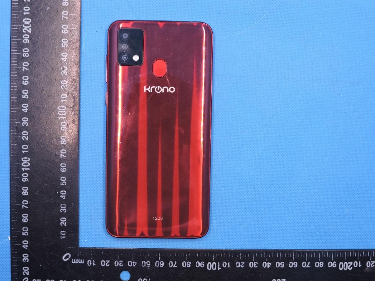
2AFD9NETADVANCE
Nov 09, 2020SMART PHONE
Equipment Class
PCE - PCS Licensed Transmitter held to ear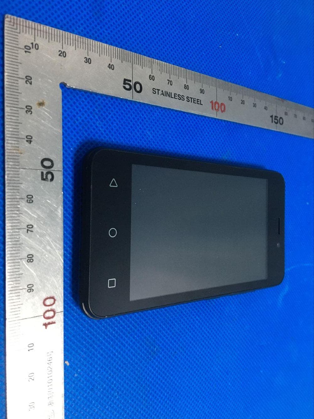
2AFD9NETONE
Jul 22, 2020Smart Phone
Equipment Class
DSS - Part 15 Spread Spectrum Transmitter