2AFYS-KLK915MWIFCThe Wirnet iFemtoCell is an indoor LoRa Gateway for IoT chain.
KERLINK SA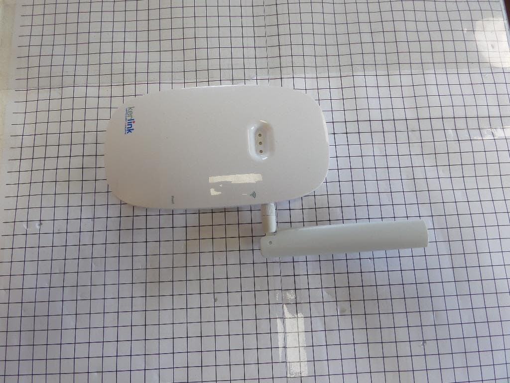
Click to zoom
Application Details
- Equipment Class
- DTS - Digital Transmission System
- Date of Grant
- Jul 11, 2021
- Application Purpose
- Original Equipment
- Date of Application
- Jul 11, 2021
- Equipment Note
- The Wirnet iFemtoCell is an indoor LoRa Gateway for IoT chain.
- Frequency Range
- 923.30000000 - 927.50000000
- Company
- KERLINK SA
- Country
- France
Documents & Files
Document Text
Text extracted from the exhibit documents filed with the FCC. Open a document above to read the original.
Users Manual
USER MANUAL WIRNET™ IFEMTOCELL Written by Approved by Validated by Name Benoît LE TEXIER Martin CHAPLET Pierre TALVAZ Entity KLK/KIS/DRD/BS KLK/KIS/DRD/BS KLK/KIS/DRD/SPT Date 26/02/2019 26/02/2019 14/03/2019 HISTORY Date Modification Author Version 19/10/2017 First version Vincent LOUVEAU 0.3 09/11/2018 Approbation and validation Vincent LOUVEAU 1.0 09/11/2018 §11.3 : Update 923MHz certifications Vincent LOUVEAU 1.1 18/02/2019 KerOS v4.0 modifications : • §6.4 : Add Wi-Fi direct connection • §6.6 : Update procedure and new configuration capabilities Benoît LE TEXIER 1.2 26/02/2019 Approbation Benoît LE TEXIER 1.3 14/03/2019 Validation Benoît LE TEXIER 2.0 30/03/2021 Modification of the Indonesia label 3.0 25/06/2021 Modification of the FCC ID, IC ID and Model name for the Wirnet iFemtoCell 915 Pierre DEMETZ 3.1 28/06/2021 Add antenna caracteristics Pierre DEMETZ 3.2 User Manual V3.1 1 User Manual of Wirnet™ iFemtoCell 1 Normal conditions of use The Wirnet™ iFemtoCell is an indoor LoRa Gateway for IoT chain. It is based on LoRa® technology provided by Semtech Company and is fully compatible and interoperable with existing LoRa LPWAN. The Wirnet™ iFemtoCell is available in three versions to cover different countries and areas around the world: Wirnet™ iFemtoCell 868MHz Wirnet™ iFemtoCell 915MHz Wirnet™ iFemtoCell 923MHz Geographical area Europe, Russia Africa Middle East, India North America Central America South America with the exception of Brazil Asia: Indonesia, Malaysia, Korea, Japan, Taiwan, Hong Kong, Thailand, Vietnam, Singapore, Philippines Oceania: Australia, New Zealand Brazil ISM band 863 - 876 MHz 902 - 928 MHz 915 - 928 MHz Downstream bandwidth (Tx of the Wirnet™ iFemtoCell) 863 - 873MHz 902 - 928 MHz 915 - 928 MHz Upstream bandwidth (Rx of the Wirnet™ iFemtoCell) 863 - 873 MHz 902 - 928 MHz 915 - 928 MHz Certifications See paragraph 11.1 See paragraph 11.2 See paragraph 11.3 Please check the appropriate version for the dedicated country. Contact your reseller if required. The present document addresses all the above Wirnet™ iFemtoCell versions. 2 Description of features Here are the main functionalities of the Wirnet™ iFemtoCell: • LongRange support: o Incorporate LoRa (TM) bidirectional communications technology: ▪ 868MHz version → RX: 863- 873MHz , TX: 863-873MHz (according to HW capabilities) ▪ 915MHz version → 902-928 MHz ISM band-hybrid mode (according to HW capabilities) ▪ 923MHz version → RX: 915-928 MHz, TX: 915-928MHz (according to HW capabilities) o 49 LoRa demodulators over 9 channels + 1 x GFSK • Embedded, remote and open low power communication station • Open development framework based on standard Linux OS • Internet connectivity over Wi-Fi, Ethernet or 3G/4G (with optional USB dongle) • USB host interface allowing local software upgrade with USB mass-storage key 3 Safety 3.1 Warnings in this manual Warnings provide important safety information. Warnings must be read before any action is taken that could generate risks to people or equipment. Refers to a critical situation. In case of non-compliance, it may result in property damage. Refers to useful information during manipulations. 3.2 Safety instructions Please read this user manual carefully. It is an integral part of the described equipment and it must be available at all time. • Only use the Wirnet™ iFemtoCell for its intended use, see chapter 1 "Normal conditions of use". • Only use the Wirnet™ iFemtoCell in the normal operating conditions described in chapter 10 "Technical characteristics". • Maintenance and repair must be carried out by qualified personnel authorized by the manufacturer. • The enclosure of the Wirnet™ iFemtoCell must not be opened by customer. • The Wirnet™ iFemtoCell should only be used with accessories or spare parts supplied by your reseller. WARNING i WARNING User Manual V3.1 2 4 Overview of Wirnet™ iFemtoCell Nomenclature: N° Components N° Components 1 Wirnet™ iFemtoCell 9 SMA connector for LoRa antenna 2 Silkscreened KERLINK marking 10 Silkscreened Wi-Fi (WPS) marking 3 Jack connector (for power supply) 11 Wi-Fi (WPS) push button 4 USB connector 12 Silkscreened Reset marking 5 RJ45 connector (Ethernet) 13 Reset push button 6 3 bicolor LEDs 14 LoRa antenna (862-873MHz, 902-928MHZ, 3dBi, 50Ω; vertical polarization) 7 Wall mounting oblong holes 15 AC power supply 8 Sticker with markings 16 User manual (this document) 5 Markings 5.1 Markings on sticker Symbol Description Symbol Description Wirnet™ iFemtoCell Type of equipment QR code Power supply informations or other marking CE marking indicating that the product complies with current European directives, or other marking depending on the country Board ID Serial number of board Marking indicating that the product complies with RoHS directives Final product ID Serial number of product Do not dispose of with domestic waste MAC ADDR MAC address Product must be installed on a non-flammable substrate (UL 94V0) Refer to the installation instructions before powering up (EU version used here as example - non contractual view) 1 2 3 4 1 5 14 6 7 8 9 10 11 12 13 15 User Manual V3.1 3 5.2 Markings on packaging Symbol Description Symbol Description Wirnet™ iFemtoCell Type of equipment QR code Final product ID Serial number of product or other marking CE marking indicating that the product complies with current European directives, or other marking depending on the country Packaging ID Identifier of packaging Marking indicating that the product complies with RoHS directives Software version Version of embedded software Do not dispose of with domestic waste MAC ADDR MAC address Product must be installed on a non-flammable substrate (UL 94V0) Refer to the installation instructions before powering up 6 Installation of Wirnet™ iFemtoCell 6.1 Mounting of the enclosure The Wirnet™ iFemtoCell enclosure must be mounted on any concrete pedestal, concrete wall or any non-flammable surface (UL94-V0). It must not be mounted on a flammable surface. The Wirn…
Text truncated - open the document above for the full version.
External Photos
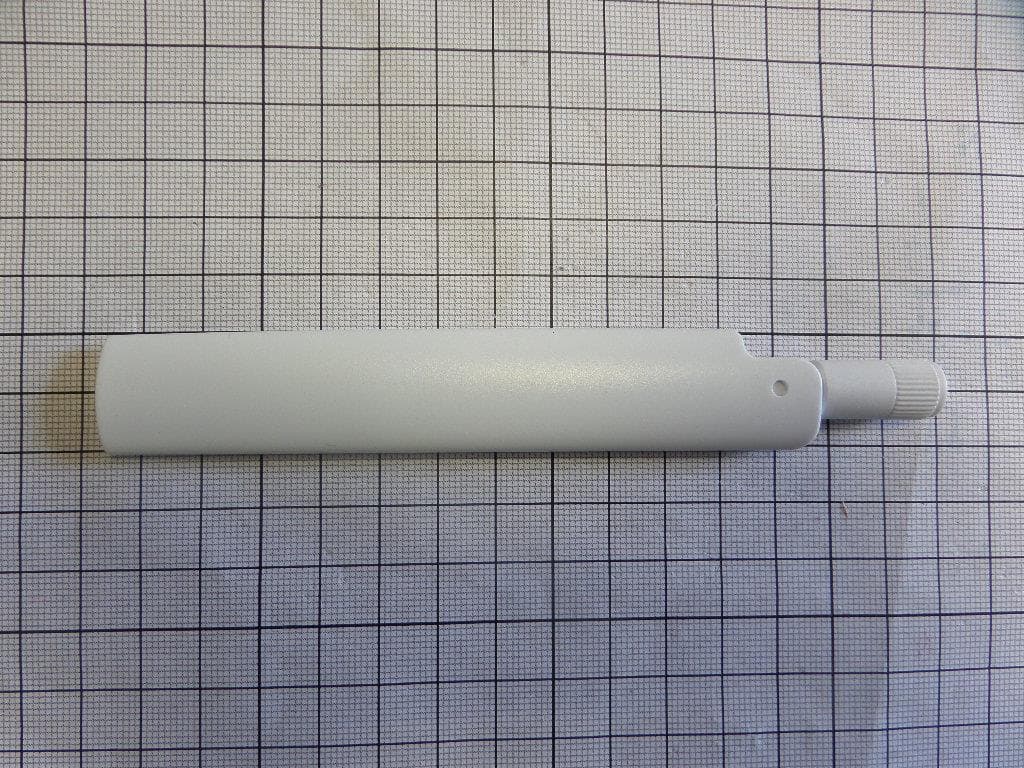
Antenna
ID Label/Location Info
LABEL
RF Exposure Info
Siège Social : Emitech - 3, rue des Coudriers - Z.A. de l’Observatoire - 78180 MONTIGNY LE BX - France Siret : 344 545 645 00022 - Tél. : 33 (0)1 30 57 55 55 - Fax : 33 (0)1 30 43 74 48 - E-mail : [email protected] - URL : www.emitech.fr S.A. au capital de 1 560 000 € - R.C.S. VERSAILLES 344 545 645 - APE 7112B S 51 RTY 000 EMF 00006 [ 0 1 ] RE-21-B308-KER-1-A Ed. 0 MPE test report According to the standard: CFR 47 FCC PART 15 Equipment under test: Wirnet iFemtoCell 915 FCC ID: 2AFYS-KLK915MWIFC Company: KERLINK Distribution: Mr DEMETZ (Company: KERLINK) Number of pages: 9 Technical Verification and Quality Approval Ed. Date Modified Page(s) Name and Function Visa 0 6-Jul-21 Creation S. LOUIS, Radio Technician Duplication of this document is only permitted for an integral photographic facsimile. It includes the number of pages referenced here above. This document is the result of testing a specimen or a sample of the product submitted. It does not imply an assessment of the conformity of the whole manufactured products of the tested sample. Information in italics are declared by the manufacturer/customer and are under his responsibility RE-21-B308-KER-1-A Ed. 0 Page 2/9 DESIGNATION OF PRODUCT: Wirnet iFemtoCell 915 Serial Number : 708BJc03000D Hardware: V3c Reference / model (P/N): Wirnet iFemtoCell 915MHz Software version: Keros 3.1.3 MANUFACTURER: KERLINK COMPANY SUBMITTING THE PRODUCT: Company: KERLINK Address: 1 RUE JACQUELINE AURIOL 35235 THORIGNE-FOUILLARD FRANCE Responsible: Mr DEMETZ DATES OF TEST: From 9-Jun-21 to 10-Jun-21 TESTING LOCATION: EMITECH ANGERS laboratory at JUIGNE SUR LOIRE (49) FRANCE FCC Accredited under US-EU MRA Designation Number: FR0009 Test Firm Registration Number: 873677 TESTED BY: T. LEDRESSEUR VISA: WRITTEN BY: T. LEDRESSEUR RE-21-B308-KER-1-A Ed. 0 Page 3/9 CONTENTS TITLE PAGE 1. INTRODUCTION ....................................................................................................................................... 4 2. PRODUCT DESCRIPTION ....................................................................................................................... 4 3. NORMATIVE REFERENCE ...................................................................................................................... 6 4. RF EXPOSURE ......................................................................................................................................... 7 REVISIONS HISTORY Revision Date Modified pages Modifications 0 16-Jun-21 / Creation RE-21-B308-KER-1-A Ed. 0 Page 4/9 1. INTRODUCTION This report presents the results of radio test carried out on the following radio equipment: Wirnet iFemtoCell 915, in accordance with normative reference. The product is a LoRa gateway composed by a LoRa function not certified and a Wi-Fi 2.4 GHz module already certified FCC ID: Z64-WL18SBMOD). / (IC ID:451l-MW18SBMOD). The LoRa can emit following 2 frequencies plan: - 923.3 MHz to 927.5 MHz (DTS class) - 903.9MHz to 905.3 MHz (Hybrid) 2. PRODUCT DESCRIPTION Category of equipment (ISED): I Class: B Utilization: Residential use Power source: 120 Vac – 60 Hz by AC/DC adapter WiFi function: Antenna type and gain: Internal ceramic antenna Operating frequency range: 2412 MHz to 2462 MHz Number of channels: 11 Channel spacing: 5 MHz RE-21-B308-KER-1-A Ed. 0 Page 5/9 LoRa function Antenna type and gain: External antenna, connector RP-SMA and gain 3dBi (TEKFUN_I50-SR-W) Hybrid Operating frequency range: From 903.9 MHz to 905.3 MHz Number of channels: 8 Channel spacing: 200kHz Modulation: LoRa (Chirp spread spectrum) Spread Factor: 9 During test the output power was adjusted at the maximal level with the following setting (Mix 11 Pa 3) DTS Operating frequency range: From 923.3 MHz to 927.5 MHz Number of channels: 8 Channel spacing: 600kHz Modulation: LoRa (Chirp spread spectrum) Spread Factor: 7 and 12 During test the output power was adjusted at the maximal level with the following setting (Mix 15 Pa 3) Power level, frequency range and channels characteristics are not user adjustable. The details pictures of the product and the circuit boards are joined with this file. RE-21-B308-KER-1-A Ed. 0 Page 6/9 3. NORMATIVE REFERENCE The standards and testing methods related throughout this report are those listed below. They are applied on the whole test report even though the extensions (version, date and amendment) are not repeated. CFR 47 (2021) Radio Frequency Devices ANSI C63.10 2013 Procedures for ComplianceTesting of Unlicensed Wireless Devices. 447498 D01 General RF RF Exposure procedures and equipment authorization policies for mobile and Exposure Guidance v06 portable equipment OET BULLETIN 65 Evaluating Compliance with FCC Guidelines for Human Exposure to Radiofrequency Electromagnetic Fields RE-21-B308-KER-1-A Ed. 0 Page 7/9 4. RF EXPOSURE Wi-Fi module : The results are extracted from test report N°FR3N2752-01C The product doesn’t use the MiMo configuration, so the maximum power is 20.59 dBm (2437 MHz, 802.11 g) The antenna gain was 2.5dBi Maximum EIRP = 0.204 W at 2437 MHz with EIRP = 20.59 dBm + 2.5 dBi In accordance with KDB 447498 D01 General RF Exposure Guidance v06: PSD= EIRP/(4*π*R 2 ) 204/(4*π*(20 cm)²)= 0.041 mW/cm² (limit = 1 mW/cm²) The equipment fulfils the requirements on power density for general population/uncontrolled exposure and therefore fulfils the requirements of 47 CFR §1.1310. MPE ratio(Wi-Fi) = = = 0.041 RE-21-B308-KER-1-A Ed. 0 Page 8/9 LoRa DTS Maximum measured conducted power =27.15 dBm EIRP with 3 dBi antenna gain = 30.15 dBm = 1035.1 mW In accordance with KDB 447498 D01 General RF Exposure Guidance v06: PSD= EIRP/(4*π*R 2 ) 1035.1/(4*π*(20 cm)²)= 0.206 mW/cm² (limit= 0.617 mW/cm² ) The equipment fulfils the requirements on power density for general population/uncontrolled exposure and therefore fulfils the requirements of 47 CFR §1.1310. MPE ratio(DTS) = = = 0.334 LoRa Hybrid Maximum measured conducted power =23.97dBm EIRP with 3 dBi…
Text truncated - open the document above for the full version.
Test Report
Siège Social : Emitech - 3, rue des Coudriers - Z.A. de l’Observatoire - 78180 MONTIGNY LE BX - France Siret : 344 545 645 00022 - Tél. : 33 (0)1 30 57 55 55 - Fax : 33 (0)1 30 43 74 48 - E-mail : [email protected] - URL : www.emitech.fr S.A. au capital de 1 560 000 € - R.C.S. VERSAILLES 344 545 645 - APE 7112B S51 RTY 000 INT 00015 [ 0 1 ] LISTE DES SITES ACCREDITES ET PORTEES DISPONIBLES SUR WWW.COFRAC.FR ACCREDITATIONS N° 1-0107, 1-0826, 1-0827, 1- 1925, 1-2069,1-2070, 1-2206, 1-2376 & 1-6086 RR-21-B308-KER-2-A Ed. 0 Certification Radio test report According to the standard: CFR 47 FCC PART 15 RSS GEN – Issue 5 RSS 247 – Issue 2 Equipment under test: Wirnet iFemtoCell 915 FCC ID: 2AFYS-KLK915MWIFC IC NUMBER: 20637-KLK915MWIFC Company: KERLINK Distribution: Mr DEMETZ (Company: KERLINK) Number of pages: 52 with 1 appendix Technical Verification and Quality Approval Ed. Date Modified Page(s) Name and Function Visa 0 6-Jul-21 Creation S. LOUIS, Radio Technician Duplication of this document is only permitted for an integral photographic facsimile. It includes the number of pages referenced here above. This document is the result of testing a specimen or a sample of the product submitted. It does not imply an assessment of the conformity of the whole manufactured products of the tested sample. Information in italics are declared by the manufacturer/customer and are under his responsibility RR-21-B308-KER-2-A Ed. 0 Page 2/52 DESIGNATION OF PRODUCT: Wirnet iFemtoCell 915 Serial Number : 708BJc03000D Hardware: V3c Reference / model (P/N): Wirnet iFemtoCell 915MHz Software version: Keros 3.1.3 MANUFACTURER: KERLINK COMPANY SUBMITTING THE PRODUCT: Company: KERLINK Address: 1 RUE JACQUELINE AURIOL 35235 THORIGNE-FOUILLARD FRANCE Responsible: Mr DEMETZ DATES OF TEST: From 8-Sep-17 to 10-Jun-21 TESTING LOCATION: EMITECH ANGERS laboratory at JUIGNE SUR LOIRE (49) FRANCE FCC Accredited under US-EU MRA Designation Number: FR0009 Test Firm Registration Number: 873677 ISED Accredited under CANADA-EU MRA Designation Number: FR0001 Industry Canada Registration Number: 4452A TESTED BY: T. LEDRESSEUR VISA: WRITTEN BY: T. LEDRESSEUR RR-21-B308-KER-2-A Ed. 0 Page 3/52 CONTENTS TITLE PAGE 1. INTRODUCTION ....................................................................................................................................... 4 2. PRODUCT DESCRIPTION ....................................................................................................................... 4 3. NORMATIVE REFERENCE ...................................................................................................................... 5 4. TEST METHODOLOGY ............................................................................................................................ 6 5. TEST EQUIPMENT CALIBRATION DATES ............................................................................................ 7 6. TESTS RESULTS SUMMARY .................................................................................................................. 9 7. MEASUREMENT UNCERTAINTY ...........................................................................................................11 8. AC CONDUCTED EMISSIONS................................................................................................................12 9. OCCUPIED BANDWIDTH .......................................................................................................................15 10. BAND EDGE ............................................................................................................................................29 11. CONDUCTED OUTPUT POWER ............................................................................................................34 12. RADIATED SPURIOUS EMISSIONS ......................................................................................................37 13. CONDUCTED POWER SPECTRAL DENSITY .......................................................................................43 APPENDIX 1: TEST EQUIPMENT LIST ........................................................................................................................... 50 REVISIONS HISTORY Revision Date Modified pages Modifications 0 17-Jun-21 / Creation RR-21-B308-KER-2-A Ed. 0 Page 4/52 1. INTRODUCTION This report presents the results of radio test carried out on the following radio equipment: Wirnet iFemtoCell 915, in accordance with normative reference. The product is a LoRa gateway composed by a LoRa function not certified and a Wi-Fi 2.4 GHz module already certified FCC ID: Z64-WL18SBMOD). / (IC ID:451l-MW18SBMOD). The LoRa can emit following 2 frequencies plan: - 923.3 MHz to 927.5 MHz (DTS class) - 903.9MHz to 905.3 MHz (Hybrid) This radio test report concern only the test realized in order to certify the LoRa DTS function, CFR47 FCC subpart C (§15.247). 2. PRODUCT DESCRIPTION Category of equipment (ISED): I Class: B Utilization: Residential use Power source: 120 Vac – 60 Hz by AC/DC adapter Antenna type and gain: External antenna, connector RP-SMA and gain 3dBi (TEKFUN_I50-SR-W) Operating frequency range: From 923.3 MHz to 927.5 MHz Number of channels: 8 Channel spacing: 600kHz Modulation: LoRa (Chirp spread spectrum) Spread Factor: 7 and 12 During test the output power was adjusted at the maximal level with the following setting (Mix 15 Pa 3) Power level, frequency range and channels characteristics are not user adjustable. The details pictures of the product and the circuit boards are joined with this file. RR-21-B308-KER-2-A Ed. 0 Page 5/52 3. NORMATIVE REFERENCE The standards and testing methods related throughout this report are those listed below. They are applied on the whole test report even though the extensions (version, date and amendment) are not repeated. CFR 47 FCC Part 15 (2021) Radio Frequency Devices ANSI C63.10 2013 Procedures for ComplianceTesting of Unlicensed Wireless Devices. 558074 D01 DTS v05 r02 …
Text truncated - open the document above for the full version.
Test Setup Photos
Anechoic chamber setup Above 1 GHz 1: Equipment Under Test 2: Measurement antenna 3: Measurement equipment 1 2 1.5 m 3 Distance : 3 m 1.5 m Turntable Installation of Equipment Under Test Anechoic chamber Position 1 Poisitin 2 Measure between 1 GHz to 18 GHz Conducted measurement setup Conducted setup
Contact Information
Applicant
YANNICK DELIBIE
Test Firm
EMITECH AngersMounir El Marzouki
Technical Specifications
| # | Rule Parts | Frequency Range | Power Output |
|---|---|---|---|
| 1 | 15C | 923.3 MHz - 927.5 MHz | 501.00 mW |
Other Applications from KERLINK SA
2AFYS-KLKFEVO915
Mar 22, 2020LoRaWAN gateway for the Internet of Things
Equipment Class
DTS - Digital Transmission System
2AFYS-KLKWIIS915
Mar 01, 2020LoRaWAN gateway for the Internet of Things
Equipment Class
DTS - Digital Transmission System
2AFYS-KLK915LOI
Nov 02, 2015Tele transmission
Equipment Class
DTS - Digital Transmission System